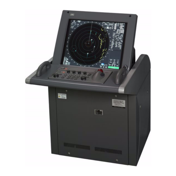
JRC JMA-9133-SA Installation Manual
Marine radar equipment
Hide thumbs
Also See for JMA-9133-SA:
- Instruction manual (572 pages) ,
- Simplified manual (24 pages) ,
- Brochure (8 pages)
Table of Contents
Advertisement
Quick Links
JMA-9133-SA
JMA-9133-SA
JMA-9132-SA
JMA-9132-SA
JMA-9123-7XA/9XA
JMA-9123-7XA/9XA
JMA-9122-6XA/9XA/6XAH
JMA-9122-6XA/9XA/6XAH
JMA-9110-6XA/6XAH
JMA-9110-6XA/6XAH
JMA-7133-SA
JMA-7133-SA
JMA-7132-SA
JMA-7132-SA
JMA-7123-7XA/9XA
JMA-7123-7XA/9XA
JMA-7122-6XA/9XA/6XAH
JMA-7122-6XA/9XA/6XAH
JMA-7110-6XA/6XAH
JMA-7110-6XA/6XAH
MARINE RADAR
MARINE RADAR
EQUIPMENT
EQUIPMENT
INSTALLATION
INSTALLATION
MANUAL
MANUAL
Advertisement
Chapters
Table of Contents

Related Manuals for JRC JMA-9133-SA


Summary of Contents for JRC JMA-9133-SA
- Page 1 JMA-9133-SA JMA-9133-SA JMA-9132-SA JMA-9132-SA JMA-9123-7XA/9XA JMA-9123-7XA/9XA JMA-9122-6XA/9XA/6XAH JMA-9122-6XA/9XA/6XAH JMA-9110-6XA/6XAH JMA-9110-6XA/6XAH JMA-7133-SA JMA-7133-SA JMA-7132-SA JMA-7132-SA JMA-7123-7XA/9XA JMA-7123-7XA/9XA JMA-7122-6XA/9XA/6XAH JMA-7122-6XA/9XA/6XAH JMA-7110-6XA/6XAH JMA-7110-6XA/6XAH MARINE RADAR MARINE RADAR EQUIPMENT EQUIPMENT INSTALLATION INSTALLATION MANUAL MANUAL...
-
Page 3: Table Of Contents
Index Cross Reference JMA-9133-SA ......................i JMA-9132-SA ......................ii JMA-9123-7XA/9XA ....................iii JMA-9122-6XA/9XA ....................iv JMA-9122-6XAH .....................v JMA-9110-6XA/6XAH ....................vi JMA-7133-SA ......................vii JMA-7132-SA .......................viii JMA-7123-7XA9XA ....................ix JMA-7122-6XA/9XA ....................x JMA-7122-6XAH ....................xi JMA-7110-6XA/6XAH ...................xii SECTION 1 EQUIPMENT COMPOSITION GENERAL COMPOSITION ..............1-1 1.1.1 JMA-9100 SERIES RADAR ............... 1-1 1.1.2... - Page 4 2.4.4 Confirmation during test run ..............2-35 2.4.5 Others ....................... 2-35 SECTION 3 INSTALLATION OF DISPLAY UNIT INSTALLATION OF DISPLAY UNIT ............3-1 3.1.1 Exterior Drawing of NCD-4990 ..............3-2 3.1.2 Exterior drawing of NCD-4990T ............... 3-3 3.1.3 Exterior drawing of NCD-4790 ..............3-6 3.1.4 Exterior drawing of NCD-4790T ...............
- Page 5 CCRP SETTING ...................4-13 MAIN BANG SUPPRESSION SETTING ..........4-14 4.10 PERFORMANCE MONITOR SETTING ..........4-16 4.11 DATE/TIME DISPLAY SETTING ............4-18 4.12 INITIALIZATION OF SCANNER OPERATION TIME ......4-20 SECTION 5 OPTION UNIT INSTALLATION OF INTERSWITCH UNIT ..........5-1 5.1.1 Equipment cable end processing ............5-1 5.1.2 Plug terminal block connection procedures ..........
- Page 6 General system diagram of JMA-9100 (Desktop type) ......6-50 6.2.4.1 General system diagram of JMA-9132-SA (Desktop) ......6-51 6.2.4.2 General system diagram of JMA-9133-SA (Desktop) ......6-52 6.2.4.3 General system diagram of JMA-9122-6XA (Desktop) ......6-53 6.2.4.4 General system diagram of JMA-9122-9XA (Desktop) ......6-54 6.2.4.5...
- Page 7 6.3.2 Inter-board connection diagram of JMA-9100 ........6-70 6.3.2.1 Inter-board connection diagram of JMA-9132-SA ......... 6-71 6.3.2.2 Inter-board connection diagram of JMA-9133-SA ........ 6-72 6.3.2.3 Inter-board connection diagram of JMA-9122-6XA/9XA ...... 6-73 6.3.2.4 Inter-board connection diagram of JMA-9122-6XAH......6-74 6.3.2.5 Inter-board connection diagram of JMA-9122-6XAH (Desktop) ...
-
Page 9: Cross Reference
JMA-9133-SA Table1-1: JMA-9100 SERIES RADAR LIST OF COMPOSITION (Self-Standing TYPE) Table1-2: JMA-9100 SERIES RADAR LIST OF COMPOSITION (Desktop TYPE) Scanner Unit: NKE-1139 Table1-5: JMA-9133-SA SCANNER and TRANSMITTER RECEIVER UNIT 2.1.2 2695110056 2.2.6 NKE-1139 type scanner 2.4 PRECAUTIONS Transmiter Receiver Unit: NTG-3230 2.3.2 NTG-3230 type transmitter receiver... -
Page 10: Jma-9132-Sa
JMA-9132-SA Table1-1: JMA-9100 SERIES RADAR LIST OF COMPOSITION (Self-Standing TYPE) Table1-2: JMA-9100 SERIES RADAR LIST OF COMPOSITION (Desktop TYPE) Scanner Unit: NKE-1130 Table1-6: JMA-9132-SA SCANNER UNIT 2.1.2 2695110056 2.2.5 NKE-1130 type scanner 2.4 PRECAUTIONS Display Unit (self standing): NCD-4990 Table1-11: NCD-4990/NCD-4990T DISPLAY UNIT 3.1 INSTALLATION OF DISPLAY UNIT 3.3.1 Connections with NKE-1125,NTG-3225,NKE-1130,NTG-3230 OPTION... -
Page 11: Jma-9123-7Xa/9Xa
Cross Reference JMA-9123-7XA/9XA Table1-1: JMA-9100 SERIES RADAR LIST OF COMPOSITION (Self-Standing TYPE) Table1-2: JMA-9100 SERIES RADAR LIST OF COMPOSITION (Desktop TYPE) Scanner Unit: NKE-1129 Table1-7: JMA-9123-7XA/JMA-9123-9XA SCANNER and TRANSMITTER-RECEIVER UNIT 2.1.2 2695110056 2.2.4 NKE-1129 type scanner 2.4 PRECAUTIONS Transmiter Receiver Unit: NTG-3225 2.3.1 NTG-3225 type transmitter receiver Display Unit (self standing): NCD-4990 Table1-11:... -
Page 12: Jma-9122-6Xa/9Xa
JMA-9122-6XA/9XA Table1-1: JMA-9100 SERIES RADAR LIST OF COMPOSITION (Self-Standing TYPE) Table1-2: JMA-9100 SERIES RADAR LIST OF COMPOSITION (Desktop TYPE) Scanner Unit: NKE-1125 Table1-8: JMA-9122-6XA/JMA-9122-9XA SCANNER UNIT 2.1.2 2695110056 2.2.3 NKE-1125 type scanner 2.4 PRECAUTIONS Display Unit (self standing): NCD-4990 Table1-11: NCD-4990/NCD-4990T DISPLAY UNIT 3.1 INSTALLATION OF DISPLAY UNIT 3.3.1 Connections with NKE-1125,NTG-3225,NKE-1130,NTG-3230 OPTION... -
Page 13: Jma-9122-6Xah
Cross Reference JMA-9122-6XAH Table1-1: JMA-9100 SERIES RADAR LIST OF COMPOSITION (Self-Standing TYPE) Table1-2: JMA-9100 SERIES RADAR LIST OF COMPOSITION (Desktop TYPE) Scanner Unit: NKE-2254-6HS Table1-9: JMA-9122-6XAH SCANNER UNIT 2.1.1 CFQ-6912-** 2.2.2 NKE-2254 type scanner 2.4 PRECAUTIONS Display Unit (self standing): NCD-4990 Table1-11:... -
Page 14: Jma-9110-6Xa/6Xah
JMA-9110-6XA/6XAH Table1-1: JMA-9100 SERIES RADAR LIST OF COMPOSITION (Self-Standing TYPE) Table1-2: JMA-9100 SERIES RADAR LIST OF COMPOSITION (Desktop TYPE) Scanner Unit: NKE-2103 Table1-10: JMA-9110-6XA/JMA-9110-6XAH SCANNER UNIT 2.1.1 CFQ-6912-** 2.2.1 NKE-2103 type scanner 2.4 PRECAUTIONS Display Unit (self standing): NCD-4990 Table1-11: NCD-4990/NCD-4990T DISPLAY UNIT 3.1 INSTALLATION OF DISPLAY UNIT 3.2 INSTALLATION OF AC-DC CONVERTER NBA-5135 5.2.1 Connection with NKE-2103 type and NKE-2254-6HS type scanners... -
Page 15: Jma-7133-Sa
Cross Reference JMA-7133-SA Table1-3: JMA-7100 SERIES RADAR LIST OF COMPOSITION (Self-Standing TYPE) Table1-4: JMA-7100 SERIES RADAR LIST OF COMPOSITION (Desktop TYPE) Scanner Unit: NKE-1139 Table1-12: JMA-7133-SASCANNER and TRANSMITTER RECEIVER UNIT 2.1.2 2695110056 2.2.6 NKE-1139 type scanner 2.4 PRECAUTIONS Transmiter Receiver Unit: NTG-3230 2.3.2 NTG-3230 type transmitter receiver Display Unit (self standing): NCD-4790 Table1-18:... -
Page 16: Jma-7132-Sa
JMA-7132-SA Table1-3: JMA-7100 SERIES RADAR LIST OF COMPOSITION (Self-Standing TYPE) Table1-4: JMA-7100 SERIES RADAR LIST OF COMPOSITION (Desktop TYPE) Scanner Unit: NKE-1139 Table1-13: JMA-7132-SA SCANNER UNIT 2.1.2 2695110056 2.2.5 NKE-1130 type scanner 2.4 PRECAUTIONS Display Unit (self standing): NCD-4790 Table1-18: NCD-4790/NCD-4790T DISPLAY UNIT 3.1 INSTALLATION OF DISPLAY UNIT 3.3.1 Connections with NKE-1125,NTG-3225,NKE-1130,NTG-3230 OPTION... -
Page 17: Jma-7123-7Xa9Xa
Cross Reference JMA-7123-7XA9XA Table1-3: JMA-7100 SERIES RADAR LIST OF COMPOSITION (Self-Standing TYPE) Table1-4: JMA-7100 SERIES RADAR LIST OF COMPOSITION (Desktop TYPE) Scanner Unit: NKE-1139 Table1-14: JMA-7123-7XA/JMA-7123-9XASCANNER and TRANSMITTER RECEIVER UNIT 2.1.2 2695110056 2.2.4 NKE-1129 type scanner 2.4 PRECAUTIONS Transmiter Receiver Unit: NTG-3225 2.3.1 NTG-3225 type transmitter receiver Display Unit (self standing): NCD-4790 Table1-18:... -
Page 18: Jma-7122-6Xa/9Xa
JMA-7122-6XA/9XA Table1-3: JMA-7100 SERIES RADAR LIST OF COMPOSITION (Self-Standing TYPE) Table1-4: JMA-7100 SERIES RADAR LIST OF COMPOSITION (Desktop TYPE) Scanner Unit: NKE-1125 Table1-15: JMA-7122-6XA/JMA-7122-9XA SCANNER UNIT 2.1.2 2695110056 2.2.3 NKE-1125 type scanner 2.4 PRECAUTIONS Display Unit (self standing): NCD-4790 Table1-18: NCD-4790/NCD-4790T DISPLAY UNIT 3.1 INSTALLATION OF DISPLAY UNIT 3.3.1 Connections with NKE-1125,NTG-3225,NKE-1130,NTG-3230 OPTION... -
Page 19: Jma-7122-6Xah
Cross Reference JMA-7122-6XAH Table1-3: JMA-7100 SERIES RADAR LIST OF COMPOSITION (Self-Standing TYPE) Table1-4: JMA-7100 SERIES RADAR LIST OF COMPOSITION (Desktop TYPE) Scanner Unit: NKE-2254-6HS Table1-16: JMA-7122-6XAH SCANNER UNIT 2.1.1 CFQ-6912-** 2.2.2 NKE-2254 type scanner 2.4 PRECAUTIONS Display Unit (self standing): NCD-4790 Table1-18:... -
Page 20: Jma-7110-6Xa/6Xah
JMA-7110-6XA/6XAH Table1-3: JMA-7100 SERIES RADAR LIST OF COMPOSITION (Self-Standing TYPE) Table1-4: JMA-7100 SERIES RADAR LIST OF COMPOSITION (Desktop TYPE) Scanner Unit: NKE-2103 Table1-17: JMA-7110-6XA/JMA-7110-6XAH SCANNER UNIT 2.1.1 CFQ-6912-** 2.2.1 NKE-2103 type scanner 2.4 PRECAUTIONS Display Unit (self standing): NCD-4790 Table1-18: NCD-4790/NCD-4790T DISPLAY UNIT 3.1 INSTALLATION OF DISPLAY UNIT 3.2 INSTALLATION OF AC-DC CONVERTER NBA-5135 3.3.2 Connections with NKE-2103,NKE-2254... -
Page 21: Equipment Composition
Modified November 20, 2008 11:28 1 EQUIPMENT COMPOSITION 2 INSTALLATION OF SCANNER UNIT 3 INSTALLATION OF DISPAY UNIT 4 INITIAL SETTING 5 OPTION UNIT 6 APPENDIX... - Page 23 SECTION 1 EQUIPMENT COMPOSITION EQUIPMENT COMPOSITION GENERAL COMPOSITION ..............1-1 1.1.1 JMA-9100 SERIES RADAR ............... 1-1 1.1.2 JMA-7100 SERIES RADAR ............... 1-2 LIST OF CIRCUITS ................1-4 1.2.1 JMA-9100 SERIES RADAR ............... 1-4 1.2.2 JMA-7100 SERIES RADAR ..............1-11...
-
Page 25: General Composition
Table1-1: JMA-9100 SERIES RADAR LIST OF COMPOSITION (Self-Standing TYPE) MODEL SCANNER UNIT RADIATOR PERFORMANCE TRANSMITTERR D I S P L A Y AC-DC MONITOR ECEIVER UNIT UNIT CONVERTER JMA-9133-SA NKE-1139 NJU-84 NTG-3230 NCD-4990 ― JMA-9132-SA NKE-1130 ― JMA-9123-7XA NKE-1129-7 NAX-16B-7... - Page 26 JMA-9100/7100 Installation Manual > 1.EQUIPMENT COMPOSITION > 1.1 GENERAL COMPOSITION Ex)NKE-1139-1 D, NKE-1129-92 D, NKE-2254-6HSD, 1: AC 100-115V 50/60Hz 1φ 2: AC 220-240V 50/60Hz 1φ D: HEATER OPTION 1.1.2 JMA-7100 SERIES RADAR Table1-3: JMA-7100 SERIES RADAR LIST OF COMPOSITION (Self-Standing TYPE) MODEL SCANNER UNIT RADIATOR...
- Page 27 JMA-9100/7100 Installation Manual > 1.EQUIPMENT COMPOSITION > 1.1 GENERAL COMPOSITION *1Input voltage is selectable. '1' or '2' suffix is attached to model name of scanner unit. '1' means AC100-115V(50/60Hz) and '2' means AC220-240V(50/60Hz) for type of scanner unit NKE-1139,NKE-1130,NKE-1129-7,NKE-1129-9,NKE-1125- 6 and NKE-1125-9. Others are DC input. *2HEATER OPTION is available at suffix 'D' exclude type NKE-2103.
-
Page 28: Jma-9100 Series Radar
JMA-9100/7100 Installation Manual > 1.EQUIPMENT COMPOSITION > 1.2 LIST OF CIRCUITS LIST OF CIRCUITS 1.2.1 JMA-9100 SERIES RADAR Table1-5: JMA-9133-SA SCANNER and TRANSMITTER RECEIVER UNIT NKE-1139-1 NKE-1139-2 CAX-14 SCANNER SCANNER UNIT INTERCONNECTION UNIT RADIATOR CTG-270 SAFETY SWITCH CSD-657 ENCODER CHT-71A1... - Page 29 JMA-9100/7100 Installation Manual > 1.EQUIPMENT COMPOSITION > 1.2 LIST OF CIRCUITS Table1-6: JMA-9132-SA SCANNER UNIT NKE-1130-1 NKE-1130-2 SCANNER CAX-13 SCANNER UNIT INTERCONNECTION UNIT RADIATOR CTG-270 SAFETY SWITCH CSD-656 ENCODER CHT-71A MOTOR MDBW10823 7EPRD0035 7EPRD0034 AC100V MOTOR DRIVER AC220V MOTOR DRIVER BREAK CIRCUIT CFA-255 BREAK CONTROL CIRCUIT...
- Page 30 JMA-9100/7100 Installation Manual > 1.EQUIPMENT COMPOSITION > 1.2 LIST OF CIRCUITS Table1-7: JMA-9123-7XA/JMA-9123-9XA SCANNER TRANSMITTER-RECEIVER UNIT NKE-1129-1 NKE-1129-2 S C A N N E R SCANNER UNIT CAX-12 INTERCONNECTION UNIT SAFETY SWITCH CSD-655 ENCODER CHT-71A1 MOTOR MDBW10822 AC100V MOTOR DRIVER 7EPRD0035 AC220V MOTOR DRIVER 7EPRD0034...
- Page 31 JMA-9100/7100 Installation Manual > 1.EQUIPMENT COMPOSITION > 1.2 LIST OF CIRCUITS Table1-8: JMA-9122-6XA/JMA-9122-9XA SCANNER UNIT NKE-1125-61,NKE-1125-91 NKE-1125-62,NKE-1125-92 SCANNER SCANNER UNIT CAX-11 UNIT INTERCONNECTION SAFETY SWITCH CSD-654 ENCODER CHT-71A MOTOR MDBW10822 7EPRD0035 7EPRD0034 AC100V MOTOR DRIVER AC220V MOTOR DRIVER BREAK CIRCUIT CFA-253 BREAK CONTROL CIRCUIT CCB-655...
- Page 32 JMA-9100/7100 Installation Manual > 1.EQUIPMENT COMPOSITION > 1.2 LIST OF CIRCUITS Table1-9: JMA-9122-6XAH SCANNER UNIT NKE-2254-6HS SCANNER UNIT SCANNER UNIT CAX-15 INTERCONNECTION SAFETY SWITCH CSD-653 ENCODER CHT-71A MOTOR 7BDRD0045A MOTOR CONTROL CBD-1779 POWER SUPPLY BREAK CIRCUIT CFA-257 MODULATOR UNIT NMA-550-1 MODULATOR UNIT CMB-404...
- Page 33 JMA-9100/7100 Installation Manual > 1.EQUIPMENT COMPOSITION > 1.2 LIST OF CIRCUITS Table1-10: JMA-9110-6XA/JMA-9110-6XAH SCANNER UNIT NKE-2103-6,NKE-2103-6HS SCANNER UNIT SCANNER UNIT CAX-10 INTERCONNECTION ENCODER CHT-71A MOTOR 7BDRD0048 BREAK CIRCUIT CFA-252 T R A N S M I T T E R NZT-2103 RECEIVER UNIT T R A N S M I T T E R...
- Page 34 JMA-9100/7100 Installation Manual > 1.EQUIPMENT COMPOSITION > 1.2 LIST OF CIRCUITS Table1-11: NCD-4990/NCD-4990T DISPLAY UNIT NCD-4990 NCD-4990T RADAR NDC-1399-9 NDC-1399-9 PROCESS RADAR PROCESS CDC-1324 CIRCUIT UNIT PROCESS CDC-1325 CIRCUIT ARPA PROCESS CDC-1186D CIRCUIT GYRO I/FCIRCUIT CMJ-462E MOTHER BOARD CQC-1192 TERMINAL BOARD CQD-2097 CIRCUIT POWER SUPPLY...
-
Page 35: Jma-7100 Series Radar
JMA-9100/7100 Installation Manual > 1.EQUIPMENT COMPOSITION > 1.2 LIST OF CIRCUITS 1.2.2 JMA-7100 SERIES RADAR Table1-12: JMA-7133-SASCANNER and TRANSMITTER RECEIVER UNIT NKE-1139-1 NKE-1139-2 S C A N N E R SCANNER UNIT CAX-14 INTERCONNECTION UNIT RADIATOR CTG-270 SAFETY SWITCH CSD-657 ENCODER CHT-71A1 MOTOR... - Page 36 JMA-9100/7100 Installation Manual > 1.EQUIPMENT COMPOSITION > 1.2 LIST OF CIRCUITS Table1-13: JMA-7132-SA SCANNER UNIT NKE-1130-1 NKE-1130-2 SCANNER SCANNER UNIT CAX-13 INTERCONNECTION UNIT RADIATOR CTG-270 SAFETY SWITCH CSD-656 ENCODER CHT-71A MOTOR MDBW10823 7EPRD0035 7EPRD0034 AC100V MOTOR DRIVER AC220V MOTOR DRIVER BREAK CIRCUIT CFA-255 CCB-655...
- Page 37 JMA-9100/7100 Installation Manual > 1.EQUIPMENT COMPOSITION > 1.2 LIST OF CIRCUITS Table1-14: JMA-7123-7XA/JMA-7123-9XA SCANNER and TRANSMITTER RECEIVER UNIT NKE-1129-71,NKE-1129-91 NKE-1129-72,NKE-1129-92 S C A N N E R CAX-12 SCANNER UNIT INTERCONNECTION UNIT SAFETY SWITCH CSD-655 ENCODER CHT-71A1 MOTOR MDBW10822 7EPRD0035 7EPRD0034 AC100V MOTOR DRIVER AC220V MOTOR DRIVER...
- Page 38 JMA-9100/7100 Installation Manual > 1.EQUIPMENT COMPOSITION > 1.2 LIST OF CIRCUITS Table1-15: JMA-7122-6XA/JMA-7122-9XA SCANNER UNIT NKE-1125-61,NKE-1125-91 NKE-1125-62,NKE-1125-92 S C A N N E R SCANNER UNIT CAX-11 UNIT INTERCONNECTION SAFETY SWITCH CSD-654 ENCODER CHT-71A MOTOR MDBW10822 AC100V MOTOR DRIVER 7EPRD0035 AC220VMOTOR DRIVER 7EPRD0034 BREAKCIRCUIT...
- Page 39 JMA-9100/7100 Installation Manual > 1.EQUIPMENT COMPOSITION > 1.2 LIST OF CIRCUITS Table1-16: JMA-7122-6XAH SCANNER UNIT NKE-2254-6HS SCANNER UNIT SCANNER UNIT CAX-15 INTERCONNECTION SAFETY SWITCH CSD-653 ENCODER CHT-71A MOTOR 7BDRD0045A MOTOR CONTROL CBD-1779 POWERSUPPLY BREAK CIRCUIT CFA-257 MODULATOR UNIT NMA-550-1 MODULATOR UNIT CMB-404 NTERCONNECTION...
- Page 40 JMA-9100/7100 Installation Manual > 1.EQUIPMENT COMPOSITION > 1.2 LIST OF CIRCUITS Table1-17: JMA-7110-6XA/JMA-7110-6XAH SCANNER UNIT NKE-2103-6,NKE-2103-6HS SCANNER UNIT SCANNER UNIT CAX-10 INTERCONNECTION ENCODER CHT-71A MOTOR 7BDRD0048 BREAK CIRCUIT CFA-252 T R A N S M I T T E R NZT-2103 RECEIVER UNIT CMK-599...
- Page 41 JMA-9100/7100 Installation Manual > 1.EQUIPMENT COMPOSITION > 1.2 LIST OF CIRCUITS Table1-18: NCD-4790/NCD-4790T DISPLAY UNIT NCD-4790 NCD-4790T NDC-1399-7 NDC-1399-7 RADAR PROCESS UNIT RADAR PROCESS CDC-1324 CIRCUIT PROCESS CDC-1325 CIRCUIT ARPA PROCESS CDC-1186D CIRCUIT GYRO I/FCIRCUIT CMJ-462E MOTHER BOARD CQC-1192 T E R M I N A L CQD-2097 BOARD CIRCUIT POWER SUPPLY...
- Page 42 JMA-9100/7100 Installation Manual > 1.EQUIPMENT COMPOSITION > 1.2 LIST OF CIRCUITS 1- 18...
-
Page 43: Installation Of Scanner Unit
SECTION 2 INSTALLATION OF SCANNER UNIT INSTALLATION OF SCANNER UNIT EQUIPMENT CABLE ................2-1 2.1.1 CFQ-6912-** ....................2-1 2.1.2 2695110056 ....................2-2 2.1.3 2695111153 ....................2-3 2.1.4 Cable end processing method ..............2-4 2.1.5 Connection to the display-unit side terminal block ....... 2-7 INSTALLATION OF SCANNER UNIT ............2-8 2.2.1 NKE-2103 type scanner ................ - Page 44 2.4.1 Installation of scanner unit ..............2-26 2.4.2 Routing coaxial cable and flexible waveguide ........2-29 2.4.3 Scanner installation position ..............2-31 2.4.4 Confirmation during test run ..............2-35 2.4.5 Others ....................... 2-35...
-
Page 45: Equipment Cable
JMA-9100/7100 Installation Manual > 2.INSTALLATION OF SCANNER UNIT > 2.1 EQUIPMENT CABLE EQUIPMENT CABLE 2.1.1 CFQ-6912-** This is a 19-core shielded composite cable. The cable length is indicated in the asterisks ** area in the model name, and the available cable lengths are 5, 10, 20, 30, 40, 50, and 65 meters. This cable is used to connect an NKE-2103 type scanner or an NKE-2254 type scanner to the display unit. - Page 46 JMA-9100/7100 Installation Manual > 2.INSTALLATION OF SCANNER UNIT > 2.1 EQUIPMENT CABLE 2.1.2 2695110056 This is a 14-core shielded composite cable. This cable is used to connect an NKE-1125 type scanner or an NKE-1130 type scanner, and an NTG-3225 type transmitter-receiver or a NTG-3230 type transmitter-receiver to the display unit.
- Page 47 JMA-9100/7100 Installation Manual > 2.INSTALLATION OF SCANNER UNIT > 2.1 EQUIPMENT CABLE 2.1.3 2695111153 This is an 18-core shielded composite cable. This cable is used to connect an interswitch to the display unit. Fig 2-3: Cross-sectional drawing of 2695111153 Table2-3: 2695111153 wire Wire NO.
-
Page 48: Cable End Processing Method
JMA-9100/7100 Installation Manual > 2.INSTALLATION OF SCANNER UNIT > 2.1 EQUIPMENT CABLE 2.1.4 Cable end processing method Allow for sufficient cable length so that maintenance, inspection, and repair work can be easily executed. Ensure a place to store the cable. CFQ-6912 Cut off the metal shell connector. - Page 49 JMA-9100/7100 Installation Manual > 2.INSTALLATION OF SCANNER UNIT > 2.1 EQUIPMENT CABLE Process each cable end according to the procedures shown below. Coaxial Cable Shield Cable (twisted pair) Shield Cable Vinyl Cable Fig 2-6: CFQ-6912 End processing of each wire Twist each pair of the following colored wires and clamp them to the crimp-type terminal.
- Page 50 JMA-9100/7100 Installation Manual > 2.INSTALLATION OF SCANNER UNIT > 2.1 EQUIPMENT CABLE 2695110056 、 2695111153 Remove about one meter of the outer skin, and then process the double braided shield according to the procedures shown below. abt. 80 mm Inner Shield terminal Outer Shield 2695110056...
-
Page 51: Connection To The Display-Unit Side Terminal Block
JMA-9100/7100 Installation Manual > 2.INSTALLATION OF SCANNER UNIT > 2.1 EQUIPMENT CABLE 2.1.5 Connection to the display-unit side terminal block The terminal block of the display unit's terminal board circuit is a plug terminal block which does not require a crimp-type terminal. Connection procedures are described below. -
Page 52: Installation Of Scanner Unit
JMA-9100/7100 Installation Manual > 2.INSTALLATION OF SCANNER UNIT > 2.2 INSTALLATION OF SCANNER UNIT INSTALLATION OF SCANNER UNIT 2.2.1 NKE-2103 type scanner 2- 8... - Page 53 JMA-9100/7100 Installation Manual > 2.INSTALLATION OF SCANNER UNIT > 2.2 INSTALLATION OF SCANNER UNIT 2- 9...
- Page 54 JMA-9100/7100 Installation Manual > 2.INSTALLATION OF SCANNER UNIT > 2.2 INSTALLATION OF SCANNER UNIT 2- 10...
-
Page 55: Nke-2254 Type Scanner
JMA-9100/7100 Installation Manual > 2.INSTALLATION OF SCANNER UNIT > 2.2 INSTALLATION OF SCANNER UNIT 2.2.2 NKE-2254 type scanner 2- 11... - Page 56 JMA-9100/7100 Installation Manual > 2.INSTALLATION OF SCANNER UNIT > 2.2 INSTALLATION OF SCANNER UNIT 2- 12...
-
Page 57: Nke-1125 Type Scanner
JMA-9100/7100 Installation Manual > 2.INSTALLATION OF SCANNER UNIT > 2.2 INSTALLATION OF SCANNER UNIT 2.2.3 NKE-1125 type scanner 2- 13... - Page 58 JMA-9100/7100 Installation Manual > 2.INSTALLATION OF SCANNER UNIT > 2.2 INSTALLATION OF SCANNER UNIT 2- 14...
-
Page 59: Nke-1129 Type Scanner
JMA-9100/7100 Installation Manual > 2.INSTALLATION OF SCANNER UNIT > 2.2 INSTALLATION OF SCANNER UNIT 2.2.4 NKE-1129 type scanner 2- 15... - Page 60 JMA-9100/7100 Installation Manual > 2.INSTALLATION OF SCANNER UNIT > 2.2 INSTALLATION OF SCANNER UNIT 2- 16...
-
Page 61: Nke-1130 Type Scanner
JMA-9100/7100 Installation Manual > 2.INSTALLATION OF SCANNER UNIT > 2.2 INSTALLATION OF SCANNER UNIT 2.2.5 NKE-1130 type scanner 2- 17... - Page 62 JMA-9100/7100 Installation Manual > 2.INSTALLATION OF SCANNER UNIT > 2.2 INSTALLATION OF SCANNER UNIT 2- 18...
-
Page 63: Nke-1139 Type Scanner
JMA-9100/7100 Installation Manual > 2.INSTALLATION OF SCANNER UNIT > 2.2 INSTALLATION OF SCANNER UNIT 2.2.6 NKE-1139 type scanner 2- 19... - Page 64 JMA-9100/7100 Installation Manual > 2.INSTALLATION OF SCANNER UNIT > 2.2 INSTALLATION OF SCANNER UNIT 2- 20...
-
Page 65: Installation Of Transmitter Receiver Unit
JMA-9100/7100 Installation Manual > 2.INSTALLATION OF SCANNER UNIT > 2.3 INSTALLATION OF TRANSMITTER RECEIVER UNIT INSTALLATION OF TRANSMITTER RECEIVER UNIT 2.3.1 NTG-3225 type transmitter receiver 2- 21... - Page 66 JMA-9100/7100 Installation Manual > 2.INSTALLATION OF SCANNER UNIT > 2.3 INSTALLATION OF TRANSMITTER RECEIVER UNIT 2- 22...
- Page 67 JMA-9100/7100 Installation Manual > 2.INSTALLATION OF SCANNER UNIT > 2.3 INSTALLATION OF TRANSMITTER RECEIVER UNIT 2- 23...
-
Page 68: Ntg-3230 Type Transmitter Receiver
JMA-9100/7100 Installation Manual > 2.INSTALLATION OF SCANNER UNIT > 2.3 INSTALLATION OF TRANSMITTER RECEIVER UNIT 2.3.2 NTG-3230 type transmitter receiver 2- 24... - Page 69 JMA-9100/7100 Installation Manual > 2.INSTALLATION OF SCANNER UNIT > 2.3 INSTALLATION OF TRANSMITTER RECEIVER UNIT 2- 25...
-
Page 70: Precautions
JMA-9100/7100 Installation Manual > 2.INSTALLATION OF SCANNER UNIT > 2.4 PRECAUTIONS PRECAUTIONS 2.4.1 Installation of scanner unit Precautions for transporting and storing the scanner • An scanner is a heavy load. Be very careful about handling it. • Do not allow the scanner fall on its side while it is stored or being installed. •... - Page 71 JMA-9100/7100 Installation Manual > 2.INSTALLATION OF SCANNER UNIT > 2.4 PRECAUTIONS Installation procedures a. Maintain a flat level surface on which to install the scanner. • Use sufficiently thick steel material and reinforcement material for the scanner's installation surface (mount base) to reduce vibration and impact. Keep the mount base flat and smooth.
- Page 72 JMA-9100/7100 Installation Manual > 2.INSTALLATION OF SCANNER UNIT > 2.4 PRECAUTIONS Fig 2-14: Use of washer and corrosion-resistant measures d. Grounding and corrosion-resistant measures • Ground the scanner chassis and the installation surface (hull) by using an earth line. Apply sealant to the connection portion of the earth line to prevent corrosion and damage by vibration (Fig 2-15).
-
Page 73: Routing Coaxial Cable And Flexible Waveguide
JMA-9100/7100 Installation Manual > 2.INSTALLATION OF SCANNER UNIT > 2.4 PRECAUTIONS 2.4.2 Routing coaxial cable and flexible waveguide In the case of the three-unit system consisting of the display unit, transmitter- receiver, and the scanner, use a Coaxial cable, shown in Fig 2-16, between the transmitter-receiver and the scanner for the S-band, and use a Flexible waveguide, shown in Fig 2-17, for the X-band. - Page 74 JMA-9100/7100 Installation Manual > 2.INSTALLATION OF SCANNER UNIT > 2.4 PRECAUTIONS Permissible bending radius • The permissible bending radius R of flexible waveguide is 200mm/400mm (E-bent/H- bent). More sharp bending with less radius than this must be avoided. • The permissible bending radius R of coaxial cable is 350mm. More sharp bending with less radius than this must be avoided.
-
Page 75: Scanner Installation Position
JMA-9100/7100 Installation Manual > 2.INSTALLATION OF SCANNER UNIT > 2.4 PRECAUTIONS 2.4.3 Scanner installation position Physical selection criteria • Install the scanner at the center of the mast on the keel line. • If the scanner cannot be installed at the above position for some reason, the amount of deviation must be minimized. - Page 76 JMA-9100/7100 Installation Manual > 2.INSTALLATION OF SCANNER UNIT > 2.4 PRECAUTIONS • Avoid having a rope or signal flag from winding around the radiating section thereby preventing it from rotating. • Avoid the effects of dust and heat caused by smoke from a chimney. •...
- Page 77 JMA-9100/7100 Installation Manual > 2.INSTALLATION OF SCANNER UNIT > 2.4 PRECAUTIONS the convenience of the service staff who take care of installation, maintenance, adjustment, and repair of the scanner by providing adequate footholds to the mounting rack and the radar mast. Installation Installation Height...
- Page 78 JMA-9100/7100 Installation Manual > 2.INSTALLATION OF SCANNER UNIT > 2.4 PRECAUTIONS • To avoid interference with other equipment and to prevent radio noise from generating, do not place the VHF antenna, GPS antenna, and INMARSAT's dome within the range of the vertical beam width. •...
-
Page 79: Confirmation During Test Run
JMA-9100/7100 Installation Manual > 2.INSTALLATION OF SCANNER UNIT > 2.4 PRECAUTIONS 2.4.4 Confirmation during test run If the scanner vibrates a lot during test run, try to reduce or prevent vibration by reinforcing the scanner mount base or using wire stays attached to the radar mast. 2.4.5 Others •... - Page 80 JMA-9100/7100 Installation Manual > 2.INSTALLATION OF SCANNER UNIT > 2.4 PRECAUTIONS 2- 36...
- Page 81 SECTION 3 INSTALLATION OF DISPLAY UNIT INSTALLATION OF DISPLAY UNIT INSTALLATION OF DISPLAY UNIT ............3-1 3.1.1 Exterior Drawing of NCD-4990 ..............3-2 3.1.2 Exterior drawing of NCD-4990T ............... 3-3 3.1.3 Exterior drawing of NCD-4790 ..............3-6 3.1.4 Exterior drawing of NCD-4790T ............... 3-7 INSTALLATION OF AC-DC CONVERTER NBA-5135 ......3-10 3.2.1 NBA-5135 Packing List ................
- Page 82 CONNECTIONS WITH GYRO AND ELECTROMAGNETIC LOG ..3-27 CONNECTION WITH GYRO (IEC61162-1/2) ........3-29 CONNECTIONS WITH AIS ..............3-31 CONNECTIONS WITH ECDIS .............3-33 3.9.1 Transmission Port Setting (TX Port) ............. 3-34 3.10 CONNECTION WITH ALARM MONITORING SYSTEM .....3-36 3.11 EXAMPLE OF WIRING IN THE DEVICE ..........3-38 3.12 DISPLAY UNIT LEDS FOR VARIOUS SIGNALS ........3-39 3.12.1...
-
Page 83: Installation Of Display Unit
1. As an earth plate, a JRC code: MTB349814A is included in the self- standing display unit of NCD-4990 and NCD-4790. 2. As an earth plate, a JRC code: MTB349495 is included in the desktop display unit of NCD-4990T and NCD-4790T. -
Page 84: Exterior Drawing Of Ncd-4990
JMA-9100/7100 Installation Manual > 3.INSTALLATION OF DISPLAY UNIT > 3.1 INSTALLATION OF DISPLAY UNIT 3.1.1 Exterior Drawing of NCD-4990 Fig 3-1: Exterior drawing of NCD-4990 3- 2... -
Page 85: Exterior Drawing Of Ncd-4990T
JMA-9100/7100 Installation Manual > 3.INSTALLATION OF DISPLAY UNIT > 3.1 INSTALLATION OF DISPLAY UNIT 3.1.2 Exterior drawing of NCD-4990T Fig 3-2: Exterior drawing of NDC-1399-9 3- 3... - Page 86 JMA-9100/7100 Installation Manual > 3.INSTALLATION OF DISPLAY UNIT > 3.1 INSTALLATION OF DISPLAY UNIT Fig 3-3: Exterior drawing of NWZ-170 3- 4...
- Page 87 JMA-9100/7100 Installation Manual > 3.INSTALLATION OF DISPLAY UNIT > 3.1 INSTALLATION OF DISPLAY UNIT Fig 3-4: Exterior drawing of NCE-5163 3- 5...
-
Page 88: Exterior Drawing Of Ncd-4790
JMA-9100/7100 Installation Manual > 3.INSTALLATION OF DISPLAY UNIT > 3.1 INSTALLATION OF DISPLAY UNIT 3.1.3 Exterior drawing of NCD-4790 Fig 3-5: Exterior drawing of NCD-4790 3- 6... -
Page 89: Exterior Drawing Of Ncd-4790T
JMA-9100/7100 Installation Manual > 3.INSTALLATION OF DISPLAY UNIT > 3.1 INSTALLATION OF DISPLAY UNIT 3.1.4 Exterior drawing of NCD-4790T Fig 3-6: Exterior drawing of NDC-1399-7 3- 7... - Page 90 JMA-9100/7100 Installation Manual > 3.INSTALLATION OF DISPLAY UNIT > 3.1 INSTALLATION OF DISPLAY UNIT Fig 3-7: Exterior drawing of NWZ-173 3- 8...
- Page 91 JMA-9100/7100 Installation Manual > 3.INSTALLATION OF DISPLAY UNIT > 3.1 INSTALLATION OF DISPLAY UNIT Fig 3-8: Exterior drawing of NCE-5163 3- 9...
-
Page 92: Installation Of Ac-Dc Converter Nba-5135
JMA-9100/7100 Installation Manual > 3.INSTALLATION OF DISPLAY UNIT > 3.2 INSTALLATION OF AC-DC CONVERTER NBA-5135 INSTALLATION OF AC-DC CONVERTER NBA-5135 When an scanner unit of either NKE-2103-6, NKE-2103-6HS, or NKE-2254-6HS is used, an AC/DC converter NBA-5135 is necessary. General model: JMA-9110-6XA, JMA-9110-6XAH, JMA-9122-6XAH JMA-7110-6XA, JMA-7110-6XAH, JMA-7122-6XAH) The installation method differs depending on whether the display unit is a model of the JMA-9100 series or the JMA-7100 series, or self-standing or desktop. - Page 93 JMA-9100/7100 Installation Manual > 3.INSTALLATION OF DISPLAY UNIT > 3.2 INSTALLATION OF AC-DC CONVERTER NBA-5135 Fig 3-9: NBA-5135 Packing List 3- 11...
-
Page 94: Exterior Drawing Of Nba-5135
JMA-9100/7100 Installation Manual > 3.INSTALLATION OF DISPLAY UNIT > 3.2 INSTALLATION OF AC-DC CONVERTER NBA-5135 3.2.2 Exterior drawing of NBA-5135 Fig 3-10: Exterior drawing of NBA-5135 3- 12... -
Page 95: Ncd-4990
JMA-9100/7100 Installation Manual > 3.INSTALLATION OF DISPLAY UNIT > 3.2 INSTALLATION OF AC-DC CONVERTER NBA-5135 3.2.3 NCD-4990 Install NBA-5135 in the self-standing display unit NCD-4990 according to the procedure below. Disconnect the AC cable, DVI cable, fan alarm cable, operating unit cable, and the power supply filter cable from the display unit. - Page 96 JMA-9100/7100 Installation Manual > 3.INSTALLATION OF DISPLAY UNIT > 3.2 INSTALLATION OF AC-DC CONVERTER NBA-5135 1. ケーブルを外す Disconnect these cables (ACケーブル、DVIケーブル、 ファンアラームケーブル、 操作部ケーブル、電源フィルタケーブル) 2.ビスを外す Remove the 8 screws. (8-NB5X10) 3.処理部ラックを前方に引き出す。 Pull out the rack of the radar process unit to the front. Fig 3-11: Equipment 1 of NBA-5135 (NCD-4990) 3.処理部ラックを前方に引き出す。 ...
- Page 97 JMA-9100/7100 Installation Manual > 3.INSTALLATION OF DISPLAY UNIT > 3.2 INSTALLATION OF AC-DC CONVERTER NBA-5135 4.NBA-5135の取り付け Mount the NBA-5135 by using five screws. ←手前/front 5-M5 奥/rear→ Fig 3-13: Equipment 3 of NBA-5135 (NCD-4990) 奥側/REAR SIDE Fig 3-14: Equipment 4 of NBA-5135 (NCD-4990) 手前側/FRONT SIDE Fig 3-15: Equipment 5 of NBA-5135 (NCD-4990)
- Page 98 JMA-9100/7100 Installation Manual > 3.INSTALLATION OF DISPLAY UNIT > 3.2 INSTALLATION OF AC-DC CONVERTER NBA-5135 TB521 TB522 Fig 3-16: Equipment 6 of NBA-5135 (NCD-4990) Connect terminal block TB521 located at the upper part of NBA-5135 to CBD- 1661. Table3-1 : Use cable H-7ZCRD1342(W406) (No.5, gray, thin, and 60cm in NBA-5135 Packing List Connect U to U, and V to V according to the label of the cable.
-
Page 99: Ncd-4990T
JMA-9100/7100 Installation Manual > 3.INSTALLATION OF DISPLAY UNIT > 3.2 INSTALLATION OF AC-DC CONVERTER NBA-5135 3.2.4 NCD-4990T In the case of the desktop display unit NCD-4990T, NBA-5135 must be installed outside the processing unit NDC-1399-9. The connection cable is 3 meters long. NBA-5135 cannot be installed in a location which exceeds 3 meters from the processing unit NDC-1399-9. -
Page 100: Ncd-4790
JMA-9100/7100 Installation Manual > 3.INSTALLATION OF DISPLAY UNIT > 3.2 INSTALLATION OF AC-DC CONVERTER NBA-5135 W408 (No.3 in Table3-1 : NBA-5135 Packing List ) is connected to the upper terminal of TB401. Connect NBA-5135 to TB401 according to the label of W408. An scanner equipment cable is connected to a vacant terminal of TB401. - Page 101 JMA-9100/7100 Installation Manual > 3.INSTALLATION OF DISPLAY UNIT > 3.2 INSTALLATION OF AC-DC CONVERTER NBA-5135 1. ケーブルを外す Disconnect these cables (ACケーブル、DVIケーブル、 ファンアラームケーブル、 操作部ケーブル、電源フィルタケーブル) 2.ビスを外す Remove the 8 screws. (8-NB5X10) 使用しないナイロン クリップを外しておく。 Remove the unused Nylon clip. 3.処理部ラックを前方に引き出す。 Pull out the rack of the radar process unit to the front.
-
Page 102: Ncd-4790
JMA-9100/7100 Installation Manual > 3.INSTALLATION OF DISPLAY UNIT > 3.2 INSTALLATION OF AC-DC CONVERTER NBA-5135 3.2.6 NCD-4790T In the case of the desktop display unit NCD-4990T, NBA-5135 must be installed outside the processing unit NDC-1399-9. The connection cable is 3 meters long. NBA-5135 cannot be installed in a location which exceeds 3 meters from the processing unit NDC-1399-9. -
Page 103: Connections With Scanner And Transceiver
VD O UT 1 VD O UT 1E TRIG O UT 1 TRIG O UT 1E BPO UT 1 CQD -1891 (JRC SUPPL Y ) BPO UT 1E W HT BZO UT 1 BZO UT 1E YEL- YEL G RN... -
Page 104: Connections With Nke-2103,Nke-2254
JMA-9100/7100 Installation Manual > 3.INSTALLATION OF DISPLAY UNIT > 3.3 CONNECTIONS WITH SCANNER AND TRANSCEIVER 3.3.2 Connections with NKE-2103,NKE-2254 Connect the device to TB4101(ANT) of terminal board circuit CQD-2097 located in the display unit (radar process unit). In the case of a self-standing display unit, connect the device to terminal block TB522 of AC/DC converter NBA-5135 in the display unit. - Page 105 JMA-9100/7100 Installation Manual > 3.INSTALLATION OF DISPLAY UNIT > 3.3 CONNECTIONS WITH SCANNER AND TRANSCEIVER For installation to the cable holding fixture, see Fig. 3 33 "Example of actual wiring. DISPLAY UNIT NCD-4990 19-CORES COMPO SITE CABLE (JRC SUPPL Y ) RADAR CFQ -6912-** H -2695111153...
-
Page 106: Connection With Gps
PWRIN1E PWROUT1 PWROUT1E VD O UT1 VD O UT1E TRIG OUT1 TRIG OUT1E PU R BPO UT1 CQD-1891 (JRC SUPPL Y ) BPO UT1E W HT BZO UT1 BZO UT1E YEL -YEL G RN MTROUT1+ YEL -W HT MTROUT1- BL U... - Page 107 JMA-9100/7100 Installation Manual > 3.INSTALLATION OF DISPLAY UNIT > 3.4 CONNECTION WITH GPS J4304 J4315 J4308 J4309 TB 2 J4305 J4312 OPE2 J4311 OPE1 PC430 TERMINAL BOARD Fig 3-23: Arrangement in TB4501 Operation check is possible by the use of the LED on the terminal board circuit CQD-2097.
-
Page 108: Connections With Vessel Speed Unit (2-Axis Log)
Connect the vessel speed unit to TB4501(LOGRX+, LOGRX-) of terminal board circuit CQD-2097 located in the display unit (processing unit). DISPLAY UNIT NCD-4990 RADAR H -2695111153 (JRC SUPPL Y ) CQD-2097 TERMIN AL BOARD (INTERSWITCH ) TB4101(AN T) VD +... -
Page 109: Connections With Gyro And Electromagnetic Log
Standard craft 12 度 /sec High speed craft 20 度 /sec DISPLAY UNIT NCD-4990 RADAR H -2695111153 (JRC SUPPL Y ) CQD-2097 TERMIN AL BO ARD (INTERSWITCH ) TB4101(AN T) VD + VD -... - Page 110 JMA-9100/7100 Installation Manual > 3.INSTALLATION OF DISPLAY UNIT > 3.6 CONNECTIONS WITH GYRO AND ELECTROMAGNETIC LOG J4304 J431 5 J4308 J4309 TB 2 J4305 J4312 OPE2 J4311 OPE1 PC430 TERMINAL BOARD Fig 3-26: Arrangement of TB4701/TB4801 3- 28...
-
Page 111: Connection With Gyro (Iec61162-1/2)
The bearing signal take from NMEA input, select the heading device to "CMPS". The gyro interface circuit can be used to interface NMEA to JRC format output that to make correct setting by referring to Section 4.1.2 NMEA Input setting. - Page 112 JMA-9100/7100 Installation Manual > 3.INSTALLATION OF DISPLAY UNIT > 3.7 CONNECTION WITH GYRO (IEC61162-1/2) DISPLAY UNIT NCD-4990 RADAR H -2695111153 (JRC SUPPL Y ) CQD -2097 TERMIN AL BOARD (INTERSWITCH ) TB4101(AN T) VD + VD - TB4201(ISW IN/O UT )
-
Page 113: Connections With Ais
Signal name AIS_RX is an input to this radar display unit. Connect the signal to the transmission port of the AIS display. DISPLAY UNIT NCD-4990 RADAR H -2695111153 (JRC SUPPLY ) CQD-2097 TERMIN AL BOARD (INTERSWITCH ) TB4101(AN T) TB 4201(ISW IN/OUT ) - Page 114 JMA-9100/7100 Installation Manual > 3.INSTALLATION OF DISPLAY UNIT > 3.8 CONNECTIONS WITH AIS AIS data can be displayed on the radar screen even if the transmission signal (AISTX+,AISTX-,AIS_TG of TB4601) from the radar display unit to the AIS is not connected. By connecting the transmission signal (AISTX+,AISTX-,AIS_TG of TB4601) from the radar display unit to the AIS, it is possible to stop the AIS alarm displayed on the radar screen.
-
Page 115: Connections With Ecdis
Target tracking information is outputted to ECDIS from TB4501(ARPATX+,ARPATX-) of terminal board circuit CQD-2097 located in the display unit (processing unit). Target tracking information is outputted from JARPATX+ and JARPATX- in the JRC format. DISPLAY UNIT NCD-4990 RADAR H -2695111153... -
Page 116: Transmission Port Setting (Tx Port)
JMA-9100/7100 Installation Manual > 3.INSTALLATION OF DISPLAY UNIT > 3.9 CONNECTIONS WITH ECDIS J4304 J4315 J4308 J4309 TB 2 J4305 J4312 OPE2 J4311 OPE1 PC430 TERMINAL BOARD Fig 3-31: Arrangement of TB4401 Upon shipment, settings are made so that target tracking information is not outputted. - Page 117 JMA-9100/7100 Installation Manual > 3.INSTALLATION OF DISPLAY UNIT > 3.9 CONNECTIONS WITH ECDIS Select the communication port through which the sentence to be set is output. Settable sentences TTM(TT)、TLL(TT)、TTD(TT)、TLB(TT)、OSD、RSD、ALR、ACK、 TTM(AIS)、TLL(AIS)、TTD(AIS)、TLB(AIS)、RemoteMaintenance、 JRC-ARPA、APB、BOD、GGA、GLL、RMC、RMB、VTG、XTE、 BWC、HDT、THS Selectable ports MAINTENANCE/LOG、NAV1、NAV2、ALARM、JARPA、ARPA、COM Select the output format, talker, and transmission interval.
-
Page 118: Connection With Alarm Monitoring System
JMA-9100/7100 Installation Manual > 3.INSTALLATION OF DISPLAY UNIT > 3.10 CONNECTION WITH ALARM MONITORING SYSTEM 3.10 CONNECTION WITH ALARM MONITORING SYSTEM This radar display unit has input/output functions for various contact signals intended for the alarm monitoring system. Connect necessary signals by referring to 6.3INTER-BOARD CONNECTION DIAGRAM. - Page 119 JMA-9100/7100 Installation Manual > 3.INSTALLATION OF DISPLAY UNIT > 3.10 CONNECTION WITH ALARM MONITORING SYSTEM J4304 J431 5 J4308 J4309 TB 2 J4305 J4312 OPE2 J4311 OPE1 PC430 TERMINAL BOARD Fig 3-32: Arrangement in TB11-14, TB4501 and TB4401 Conditions of all of the signals can be checked by LEDs on terminal board circuit CQD-2097.
-
Page 120: Example Of Wiring In The Device
JMA-9100/7100 Installation Manual > 3.INSTALLATION OF DISPLAY UNIT > 3.11 EXAMPLE OF WIRING IN THE DEVICE 3.11 EXAMPLE OF WIRING IN THE DEVICE TB4201 Interswitch TB4101 Cable Scanner or T/R Unit TB4501 TB4601 TB4401 LOG NMEA GPS LOG Pulse TB4801 Gyro Signal TB4701... -
Page 121: Display Unit Leds For Various Signals
JMA-9100/7100 Installation Manual > 3.INSTALLATION OF DISPLAY UNIT > 3.12 DISPLAY UNIT LEDS FOR VARIOUS SIGNALS 3.12 DISPLAY UNIT LEDS FOR VARIOUS SIGNALS Terminal board circuit CQD-2097 is equipped with LEDs to display operating conditions. Fig 3-34: Display unit LEDs 3-... -
Page 122: Serial Signal
JMA-9100/7100 Installation Manual > 3.INSTALLATION OF DISPLAY UNIT > 3.12 DISPLAY UNIT LEDS FOR VARIOUS SIGNALS 3.12.1 Serial Signal SCI INDICATOR (2color LED) TX: Green RX: Orange Fig 3-35: Serial Signal Monitor LED Two color LED: orange and green An orange LED turns on for reception and a green LED turns on for transmission. Refer to the function name displayed on the right of each LED. -
Page 123: Power Supply Status
JMA-9100/7100 Installation Manual > 3.INSTALLATION OF DISPLAY UNIT > 3.12 DISPLAY UNIT LEDS FOR VARIOUS SIGNALS CORRECT GREEN ORANGE IEC61162-1/2 Transmit DATA → time IEC61162-1/2 Receive DATA WRONG ORANGE BOTH ORANGE ORANGE IEC61162-1/2 Transmit DATA → time IEC61162-1/2 Receive DATA Fig 3-36: Serial Signal LED(when connected to the reception port with reversed polarity) 3.12.2... -
Page 124: Alarm Signal
JMA-9100/7100 Installation Manual > 3.INSTALLATION OF DISPLAY UNIT > 3.12 DISPLAY UNIT LEDS FOR VARIOUS SIGNALS 3.12.3 Alarm Signal IN/OUT STATUS 2color LED OUT: Green IN: Orange Fig 3-38: Contact Signal Monitor LED Contact signal conditions are displayed. Input is indicated when an orange light is illuminated, and output is indicated when a green light is illuminated. -
Page 125: Fan Alarm
JMA-9100/7100 Installation Manual > 3.INSTALLATION OF DISPLAY UNIT > 3.12 DISPLAY UNIT LEDS FOR VARIOUS SIGNALS 3.12.4 Fan Alarm FAN ALARM LED STOP: Red Fig 3-39: Fan Alarm Monitor LED This LED is turned off during normal operation. A red light is turned on when the fan stops operating. From top down, the CBD-1661 power-supply unit fan, processing unit fan, and monitor unit fan are indicated. - Page 126 JMA-9100/7100 Installation Manual > 3.INSTALLATION OF DISPLAY UNIT > 3.12 DISPLAY UNIT LEDS FOR VARIOUS SIGNALS 3- 44...
- Page 127 SECTION 4 INITIAL SETTING INITIAL SETTING GYRO INTERFACE SETTING ...............4-2 4.1.1 GYRO INPUT SETTING (STEP/SYNC setting) ......... 4-2 4.1.2 NMEA Input setting ................... 4-5 TUNE ADJUSTMENT ................4-7 BEARING ADJUSTMENT ..............4-8 RANGE ADJUSTMENT ................4-9 NAVIGATOR SETTING ................4-10 TRUE BEARING SETTING ..............4-11 ANTENNA HEIGHT SETTING .............4-12 CCRP SETTING ...................4-13 MAIN BANG SUPPRESSION SETTING ..........4-14...
- Page 129 JMA-9100/7100 Installation Manual > 4.INITIAL SETTING > Opening the [Service Man Menu] screen Procedures Use left key to hold down [Main] button located at the bottom right on the screen. CODE Input Press “0” and “ENT” The [CODE Input] screen will appear. to Service Man Menu Left-click 0 button.
-
Page 130: Gyro Interface Setting
JMA-9100/7100 Installation Manual > 4.INITIAL SETTING > 4.1 GYRO INTERFACE SETTING GYRO INTERFACE SETTING 4.1.1 GYRO INPUT SETTING (STEP/SYNC setting) The gyro interface circuit of this apparatus is designed to be compatible with almost all types of gyro compasses by flipping of a switch. Step-motor type: DC24V to DC100V Synchro-motor type: The primary excitation voltage is AC50V to 115V Before the power is turned on, switches S1, S2, S5, S6, S7 and jumper JP1 on the... - Page 131 JMA-9100/7100 Installation Manual > 4.INITIAL SETTING > 4.1 GYRO INTERFACE SETTING Procedures Set S5 at [OFF]. The connection between the gyro compass and the gyro interface are shut off. Set S6/S7 in accordance with the type of the compass being used. There are two types of gyro compasses: one type outputs a step signal and the other outputs a synchro signal.
- Page 132 JMA-9100/7100 Installation Manual > 4.INITIAL SETTING > 4.1 GYRO INTERFACE SETTING Set jumper TB105. Settings for TB105 are intended for the use of a low-voltage step signal. Between 1 and 2: Normally used Between 2 and 3: Set for the step signal of 22V or less Connect the gyro signal cable and the log signal cable to the terminal block.
-
Page 133: Nmea Input Setting
JMA-9100/7100 Installation Manual > 4.INITIAL SETTING > 4.1 GYRO INTERFACE SETTING Table4-2: Gyro and Log Select Switches (S2 Dip Switch) S2 SETTING TABLE LOG ALARM GYRO SIMULATOR LOG SIMULATOR N.A. Don't care GYRO ALARM TIME 0.2s HEADING SENSOR SOURCE NMEA(HDT/THS) GYRO SIGNAL NMEA BAUDRATE SETTING... - Page 134 JMA-9100/7100 Installation Manual > 4.INITIAL SETTING > 4.1 GYRO INTERFACE SETTING *When NMEA Input is activated, settings for 1-4 of S1 do not influence operation. (Don't care) *Do not change settings for 1-5 of S2 from default settings made upon shipment. (1-2-3-4-5 →...
-
Page 135: Tune Adjustment
JMA-9100/7100 Installation Manual > 4.INITIAL SETTING > 4.2 TUNE ADJUSTMENT TUNE ADJUSTMENT Tune control of the transmitter and the receiver is conducted. This adjustment is made at the installation and the replacement of magnetron. Procedures Open the [Service Man Menu] screen. Open the [1.Tune Adjustment] screen according to the operation shown below. -
Page 136: Bearing Adjustment
JMA-9100/7100 Installation Manual > 4.INITIAL SETTING > 4.3 BEARING ADJUSTMENT BEARING ADJUSTMENT Adjust the bearing so that bearing of the target measured by the ship's compass matches the bearing of the target image shown on the radar screen. Procedures Select the bearing display [H UP] mode. Set Image Processing (PROC) at OFF. -
Page 137: Range Adjustment
JMA-9100/7100 Installation Manual > 4.INITIAL SETTING > 4.4 RANGE ADJUSTMENT RANGE ADJUSTMENT Adjust the range so that the range of the target on the radar video screen is indicated correctly. Procedures Search the radar display for a known target of which range has been confirmed. -
Page 138: Navigator Setting
Set ON when a navigator is connected, and set OFF when a navigator is not connected. Gyro: Gyro (via gyro interface) Compass: Compass (IEC61162 specification) GPS Compass: GPS compass made by JRC LOG: Log (via gyro interface) 2AXW: Log over water (IEC61162 specification) 2AXG: Log over ground (IEC61162 specification) GPS:... -
Page 139: True Bearing Setting
JMA-9100/7100 Installation Manual > 4.INITIAL SETTING > 4.6 TRUE BEARING SETTING TRUE BEARING SETTING When a gyro signal is inputted by using GYRO I/F, there is a rare case in which the true bearing value indicated by the master gyro does not match the true bearing value indicated by this apparatus. -
Page 140: Antenna Height Setting
JMA-9100/7100 Installation Manual > 4.INITIAL SETTING > 4.7 ANTENNA HEIGHT SETTING ANTENNA HEIGHT SETTING Set the radar antenna height above sea level, but do not change this setting casually. Procedures Measure the height from the sea level to the radar antenna in advance. Open the [Service Man Menu] screen. -
Page 141: Ccrp Setting
JMA-9100/7100 Installation Manual > 4.INITIAL SETTING > 4.8 CCRP SETTING CCRP SETTING Set the CCRP position of own ship and the installation position of the radar scanner and the GPS. CCRP: Up to four locations can be inputted (select only one when in use) Radar scanner: Up to eight scanners can be inputted (automatically selected... -
Page 142: Main Bang Suppression Setting
JMA-9100/7100 Installation Manual > 4.INITIAL SETTING > 4.9 MAIN BANG SUPPRESSION SETTING MAIN BANG SUPPRESSION SETTING Main Bang Suppression is adjusted to suppress main bang, a reflection signal from a 3D circuit including wave guide tube, which generally appears as a circular image focusing on the center of the radar display. - Page 143 JMA-9100/7100 Installation Manual > 4.INITIAL SETTING > 4.9 MAIN BANG SUPPRESSION SETTING • Rotate [GAIN] control to the maximum position (clockwise fully). • Rotate the [SEA] control to achieve the strength with which main bang can be judged. Adjust the value to eliminate the main bang. [II] Main Bang Suppression Area Adjustment (MBS Area) Procedures Open the [Service Man Menu] screen.
-
Page 144: Performance Monitor Setting
JMA-9100/7100 Installation Manual > 4.INITIAL SETTING > 4.10 PERFORMANCE MONITOR SETTING 4.10 PERFORMANCE MONITOR SETTING When the following units are replaced, adjust the performance monitor according to the procedures shown in this section. • Performance monitor • Scanner unit [I] Receiving monitor adjustment (MON Adjustment) Make adjustments of the circuit that monitors the reception performance of the radar apparatus. - Page 145 JMA-9100/7100 Installation Manual > 4.INITIAL SETTING > 4.10 PERFORMANCE MONITOR SETTING [II] Transmitting monitor adjustment (MON Indicator Adjustment) Make adjustments of the circuit that monitors the transmission performance of the radar apparatus. Procedures When the radar apparatus has an inter-switch function, make settings for a master display unit.
-
Page 146: Date/Time Display Setting
JMA-9100/7100 Installation Manual > 4.INITIAL SETTING > 4.11 DATE/TIME DISPLAY SETTING 4.11 DATE/TIME DISPLAY SETTING To display the time, it is necessary to set the LOCAL TIME, LOCAL DATE and TIME ZONE. When the "ZDA" sentence of NMEA0183 is received, Date/Time is displayed automatically. - Page 147 JMA-9100/7100 Installation Manual > 4.INITIAL SETTING > 4.11 DATE/TIME DISPLAY SETTING 6. Synchronize with GPS By using the ZDA sentence sent from GPS, date and time synchronized with GPS are displayed. On: Time is synchronized with GPS. Off: Time is not synchronized with GPS. Even if this item is set at On, if the ZDA sentence is not inputted, date and time are displayed by using the clock function provided in the apparatus.
-
Page 148: Initialization Of Scanner Operation Time
JMA-9100/7100 Installation Manual > 4.INITIAL SETTING > 4.12 INITIALIZATION OF SCANNER OPERATION TIME 4.12 INITIALIZATION OF SCANNER OPERATION TIME This apparatus accumulates and stores the following operation time in the scanner. • Transmission time • Motor rotation time The above accumulated time is initialized when magnetron is replaced, or an scanner motor is replaced. - Page 149 JMA-9100/7100 Installation Manual > 4.INITIAL SETTING > 4.12 INITIALIZATION OF SCANNER OPERATION TIME [II] Motor rotation time (Clear Motor Time) Motor rotation time of the scanner is initialized. When an scanner motor is replaced, initialize motor rotation time according to the following procedures.
- Page 150 JMA-9100/7100 Installation Manual > 4.INITIAL SETTING > 4.12 INITIALIZATION OF SCANNER OPERATION TIME Open the [3.TXRX To Display Unit] screen according to the operation shown below. 3. Maintenance Menu → 5. TXRX Time → 3. TXRX To Display Unit Select YES on the confirmation screen. Scanner time stored in the control circuit located in the scanner is transferred to the display unit and stored.
- Page 151 SECTION 5 OPTION UNIT OPTION UNIT INSTALLATION OF INTERSWITCH UNIT ..........5-1 5.1.1 Equipment cable end processing ............5-1 5.1.2 Plug terminal block connection procedures .......... 5-2 5.1.3 Installation of interswitch unit ..............5-3 5.1.4 Setting ......................5-6 5.1.5 Confirmation after installation ............... 5-10 5.1.6 Inter-board connection diagram ............
- Page 152 5.3.1 Connections .................... 5-61 5.3.2 VDR I/F kit ....................5-62 5-63 INSTALLATION OF SUB-OPERATION UNIT AND EXPANSION OF TRACKBALL 5.4.1 Sub Operation Unit ................. 5-63 5.4.2 Expansion of trackball ................5-64...
-
Page 153: Installation Of Interswitch Unit
JMA-9100/7100 Installation Manual > 5.OPTION UNIT > 5.1 INSTALLATION OF INTERSWITCH UNIT INSTALLATION OF INTERSWITCH UNIT 5.1.1 Equipment cable end processing Equipment cable end processing Equipment Shielding Tape cable 30mm 20mm 280mm Fig 5-1: Equipment cable end processing End processing of each cable core Coaxial or Shield cable 6~7mm Vinyl cable... -
Page 154: Plug Terminal Block Connection Procedures
JMA-9100/7100 Installation Manual > 5.OPTION UNIT > 5.1 INSTALLATION OF INTERSWITCH UNIT 5.1.2 Plug terminal block connection procedures The terminal block of the display unit's terminal board circuit is a plug terminal block which does not require a crimp-type terminal. Connection procedures are described below. -
Page 155: Installation Of Interswitch Unit
JMA-9100/7100 Installation Manual > 5.OPTION UNIT > 5.1 INSTALLATION OF INTERSWITCH UNIT 5.1.3 Installation of interswitch unit a. NQE-3141-2A Basically, the interswitch unit is incorporated into the display unit and delivered with the wiring completed. Incorporate the interswitch unit into the port-side radar display unit. - Page 156 JMA-9100/7100 Installation Manual > 5.OPTION UNIT > 5.1 INSTALLATION OF INTERSWITCH UNIT Connect the cable (2695111153) between terminal board circuit TB4201 located on the port-side radar display unit and on the starboard-side radar display unit. Port Side Starboard Side No.1 RADAR No.2 RADAR RED-WHT J4308...
- Page 157 JMA-9100/7100 Installation Manual > 5.OPTION UNIT > 5.1 INSTALLATION OF INTERSWITCH UNIT Fig 5-6: Exterior drawing of NQE-3141-4A 5- 5...
- Page 158 JMA-9100/7100 Installation Manual > 5.OPTION UNIT > 5.1 INSTALLATION OF INTERSWITCH UNIT c. NQE-3141-8A Fig 5-7: Exterior drawing of NQE-3141-8A 5- 6...
-
Page 159: Setting
JMA-9100/7100 Installation Manual > 5.OPTION UNIT > 5.1 INSTALLATION OF INTERSWITCH UNIT Securely ground the included earth plate to the hull's earth. Connect the cable (2695111153) between interswitch unit NQE-3141-8A and terminal board TB4201 located on the each radar display unit. See Fig 5-13: NQE-3141-4A Inter-board connection diagram. - Page 160 JMA-9100/7100 Installation Manual > 5.OPTION UNIT > 5.1 INSTALLATION OF INTERSWITCH UNIT SW11 setting (expansion mode, master/slave setting) 1 2 3 4 Set all OFF. SW12 setting (radar connection setting) 2 3 4 Radar Connection Setting No. 1 display unit connected 1 ON No.
- Page 161 JMA-9100/7100 Installation Manual > 5.OPTION UNIT > 5.1 INSTALLATION OF INTERSWITCH UNIT b. NQE-3141-8A setting The internal structure of NQE-3141-8A includes two units of CCL-304R in the two-storied structure. Fig 5-10: NQE-3141-8A Internal structure Fig 5-11: Access to Lower Board of NQE-3141-8A 5-...
- Page 162 JMA-9100/7100 Installation Manual > 5.OPTION UNIT > 5.1 INSTALLATION OF INTERSWITCH UNIT • Although dip switch settings are basically the same as the settings shown in Fig 5-11: Access to Lower Board of NQE-3141-8A, it is necessary to make settings for each of the two SW12.
-
Page 163: Confirmation After Installation
JMA-9100/7100 Installation Manual > 5.OPTION UNIT > 5.1 INSTALLATION OF INTERSWITCH UNIT No. 4 display unit connected 7 ON No. 4 display unit NOT connected No. 4 antenna connected 8 ON No. 4 antenna NOT connected • Setting of lower CCL-304R, SW12 (radar connection setting) 2 3 4 Radar Connection Setting 1 ON... -
Page 164: Inter-Board Connection Diagram
BPOUT 1 BPOUT 1E BPOUT 1E CLEAR BZOUT 1 BZOUT 1 BZOUT 1E BZOUT 1E WHITE-YELLOW MTROUT 1+ MTROUT 1+ WHITE-WHITE MTROUT 1- MTROUT 1- MTORUT 1E MTORUT 1E H-2695111153 (JRC SUPPLY ) Fig 5-12: NQE-3141-2A Inter-board connection diagram 5- 12... - Page 165 JMA-9100/7100 Installation Manual > 5.OPTION UNIT > 5.1 INSTALLATION OF INTERSWITCH UNIT NQE-3141-4A H-2695111153 (JRC SUPPLY ) H-2695111153 (JRC SUPPLY ) H-2695111153 (JRC SUPPLY ) H-2695111153 (JRC SUPPLY ) Fig 5-13: NQE-3141-4A Inter-board connection diagram 5- 13...
-
Page 166: Installation Of Power Control Unit
JMA-9100/7100 Installation Manual > 5.OPTION UNIT > 5.2 INSTALLATION OF POWER CONTROL UNIT INSTALLATION OF POWER CONTROL UNIT Power control unit NQE-3167 is used when an antenna and a transmitter-receiver are installed at a location away from the bridge, such as a foremast. In the case of a two-unit type antenna, the maximum length of the cable that connects between the display unit and the antenna is 65 meters. - Page 167 JMA-9100/7100 Installation Manual > 5.OPTION UNIT > 5.2 INSTALLATION OF POWER CONTROL UNIT The connection between scanner unit and AC/DC converter NBA-5135 is not necessary. Instead, power control unit NQE-3167 supplies DC power. Fig 5-14: Connection of CFQ-6912 5- 15...
-
Page 168: Connections To Nke-1125, Ntg-3225, Nke-1130, And Ntg-3230
JMA-9100/7100 Installation Manual > 5.OPTION UNIT > 5.2 INSTALLATION OF POWER CONTROL UNIT 5.2.2 Connections to NKE-1125, NTG-3225, NKE-1130, and NTG- 3230 Use 14-core composite cable 2695110056 for the installation of those types of antennas. For the procedures for processing the cable end, see Fig 5-15: Equipment cable end processing. - Page 169 JMA-9100/7100 Installation Manual > 5.OPTION UNIT > 5.2 INSTALLATION OF POWER CONTROL UNIT Among the two cables, use coaxial cable RG-10/UY to connect the radar video signal. For the procedures for processing the cable end and the wiring procedures, see Fig 5-15: Equipment cable end processing.
-
Page 170: General System Diagram Of Power Control Unit (Jma-7100)
JMA-9100/7100 Installation Manual > 5.OPTION UNIT > 5.2 INSTALLATION OF POWER CONTROL UNIT 5.2.6 General system diagram of power control unit (JMA-7100) NKE-1130 SCANNER UNIT NJU-84 PERFORMANCE UNIT 1 4 C O R E S C O M P O S I T E C A B L E H - 2 6 9 5 1 1 0 0 5 6 M A X 2 3 φ... - Page 171 JMA-9100/7100 Installation Manual > 5.OPTION UNIT > 5.2 INSTALLATION OF POWER CONTROL UNIT NKE-1139 SCANNER UNIT NJU-84 PERFORMANCE UNIT 0 . 6/ 1 k V - D P Y C Y S- 1. 5 ( W I T H P M U N I T) NTG-3230 TRANSCEIVER UNIT C O A X I A L C A B L E...
- Page 172 JMA-9100/7100 Installation Manual > 5.OPTION UNIT > 5.2 INSTALLATION OF POWER CONTROL UNIT NKE-1125-6 SCANNER UNIT NJU-85 PERFORMANCE UNIT 1 4 C O R E S C O M P O S I T E C A B L E H - 2 6 9 5 1 1 0 0 5 6 M A X 2 3 φ...
- Page 173 JMA-9100/7100 Installation Manual > 5.OPTION UNIT > 5.2 INSTALLATION OF POWER CONTROL UNIT NKE-1125-9 SCANNER UNIT NJU-85 PERFORMANCE UNIT 1 4 C O R E S C O M P O S I T E C A B L E H - 2 6 9 5 1 1 0 0 5 6 M A X 2 3 φ...
- Page 174 JMA-9100/7100 Installation Manual > 5.OPTION UNIT > 5.2 INSTALLATION OF POWER CONTROL UNIT NKE-2254-6HS SCANNER UNIT NJU-85 PERFORMANCE UNIT 1 9 C O R E S C O M P O S I T E C A B L E 65 m MAX C F Q - 6 9 1 2- * * M A X 1 4.
- Page 175 JMA-9100/7100 Installation Manual > 5.OPTION UNIT > 5.2 INSTALLATION OF POWER CONTROL UNIT NKE-1129 SCANNER UNIT NJU-85 PERFORMANCE UNIT 0 .6 / 1k V - D P Y C Y S- 1 . 5 ( W I T H P M U N I T) NTG-3225 TRANSCEIVER UNIT F L E X I B L E W A V E G U I D E...
- Page 176 JMA-9100/7100 Installation Manual > 5.OPTION UNIT > 5.2 INSTALLATION OF POWER CONTROL UNIT NKE-1129 SCANNER UNIT NJU-85 PERFORMANCE UNIT 0 .6 /1 k V - D P Y C Y S- 1 .5 ( W I T H P M U N I T) NTG-3225 TRANSCEIVER UNIT F L E X I B L E W A V E G U I D E...
- Page 177 JMA-9100/7100 Installation Manual > 5.OPTION UNIT > 5.2 INSTALLATION OF POWER CONTROL UNIT NKE-2103-6 SCANNER UNIT NJU-85 PERFORMANCE UNIT 1 9 C O R E S C O M P O S I T E C A B L E 65m MAX C F Q - 6 9 1 2- * * M A X 1 4 .
- Page 178 JMA-9100/7100 Installation Manual > 5.OPTION UNIT > 5.2 INSTALLATION OF POWER CONTROL UNIT NKE-2103-6HS SCANNER UNIT NJU-85 PERFORMANCE UNIT 1 9 C O R E S C O M P O S I T E C A B L E 65m MAX C F Q - 6 9 1 2- * * M A X 1 4 .
- Page 179 MONITOR UNIT STEPDOWN AC220V, 60Hz,1φ TRANSFORMER (JRC SUPPLY ) max 5m NCE-5163 1 4 C O R E S C O M P O S I T E C A B L E OPERATION UNIT H -2 6 9 5 1 1 0 0 5 6...
- Page 180 MONITOR UNIT 1φ,200 W 0 .6 /1 k V - D P Y C Y S- 1 . 5 NQE-3167 NBL-175 POWER CONTROL SHIP’S MAIN UNIT (JRC SUPPLY) max 5m for HEATER STEPDOWN AC220V,60Hz,1φ TRANSFORMER NCE-5163 OPERATION UNIT H-7ZCRD1338 SHIP’S MAIN 0.
- Page 181 STEPDOWN MONITOR UNIT AC220V,60Hz,1φ TRANSFORMER (JRC SUPPLY ) max 5m NCE-5163 1 4 C O R E S C O M P O S I T E C A B L E OPERATION UNIT H - 2 6 9 5 1 1 0 0 5 6 4 0 0 m MAX M A X 2 3 φ...
- Page 182 STEPDOWN MONITOR UNIT AC220 V,60Hz,1φ TRANSFORMER (JRC SUPPLY) max 5m NCE-5163 1 4 C O R E S C O M P O S I T E C A B L E OPERATION UNIT H - 2 6 9 5 1 1 0 0 5 6 4 0 0 m MAX M A X 2 3 φ...
- Page 183 STEPDOWN MONITOR UNIT AC220V,60Hz,1φ TRANSFORMER (JRC SUPPLY ) max 5m NCE-5163 1 4 C O R E S C O M P O S I T E C A B L E OPERATION UNIT H - 2 6 9 5 1 1 0 0 5 6 4 0 0 m MAX M A X 2 3 φ...
- Page 184 MONITOR UNIT 1φ,200 W 0 .6 / 1k V - D P Y C Y S- 1 . 5 NQE-3167 NBL-175 POWER CONTROL SHIP’S MAIN UNIT (JRC SUPPLY) max 5m for HEATER STEPDOWN AC220V,60Hz,1φ TRANSFORMER NCE-5163 OPERATION UNIT H-7ZCRD1338 SHIP’S MAIN 0.
- Page 185 MONITOR UNIT 1φ,200 W 0 .6 / 1k V - D P Y C Y S- 1 . 5 NQE-3167 NBL-175 POWER CONTROL SHIP’S MAIN UNIT (JRC SUPPLY) max 5m for HEATER STEPDOWN AC220V,60Hz,1φ TRANSFORMER NCE-5163 OPERATION UNIT H-7ZCRD1338 SHIP’S MAIN 0 .6/1 k V- DPYCY - 6...
- Page 186 NWZ-173 MONITOR UNIT SHIP’S MAIN 0. 6/1k V -DPYCY - 6 AC220V,60Hz,1φ,400 VA (JRC SUPPLY) max 5m NCE-5163 OPERATION UNIT H-7ZCRD1338 Power & Control Cable 1 4 C O R E S C O M P O S I T E C A B L E...
- Page 187 NWZ-173 MONITOR UNIT SHIP’S MAIN 0. 6/1 k V- DPYCY - 6 AC220V,60Hz,1φ, 400VA (JRC SUPPLY) max 5m NCE-5163 OPERATION UNIT H-7ZCRD1338 Power & Control Cable 1 4 C O R E S C O M P O S I T E C A B L E...
-
Page 188: General System Diagram Of Power Control Unit (Jma-9100)
JMA-9100/7100 Installation Manual > 5.OPTION UNIT > 5.2 INSTALLATION OF POWER CONTROL UNIT 5.2.7 General system diagram of power control unit (JMA-9100) NKE-1130 SCANNER UNIT NJU-84 PERFORMANCE UNIT 1 4 C O R E S C O M P O S I T E C A B L E H - 2 6 9 5 1 1 0 0 5 6 M A X 2 3φ... - Page 189 ESPECIALLY INTER -WIRING CABLES BETWEEN SCANNER UNIT AND DISPLAY UNIT OF THE RADAR SHOULD NOT BE RUN PARALLEL WITH THE CABLES OF RADIO EQUIPMENT (S-BAND 30kW RADAR) JMA-9133-SA形レーダー総合系統図 GENERAL SYSTEM DIAGRAM OF RADAR TYPE JMA -9133 -SA Fig 5-36: JMA-9133-SA (w/ NQE-3167) 5- 37...
- Page 190 JMA-9100/7100 Installation Manual > 5.OPTION UNIT > 5.2 INSTALLATION OF POWER CONTROL UNIT NKE-1125-6 SCANNER UNIT NJU-85 PERFORMANCE UNIT 1 4 C O R E S C O M P O S I T E C A B L E H - 2 6 9 5 1 1 0 0 5 6 M A X 2 3 φ...
- Page 191 JMA-9100/7100 Installation Manual > 5.OPTION UNIT > 5.2 INSTALLATION OF POWER CONTROL UNIT NKE-1125-9 SCANNER UNIT NJU-85 PERFORMANCE UNIT 1 4 C O R E S C O M P O S I T E C A B L E H - 2 6 9 5 1 1 0 0 5 6 M A X 2 3 φ...
- Page 192 JMA-9100/7100 Installation Manual > 5.OPTION UNIT > 5.2 INSTALLATION OF POWER CONTROL UNIT NKE-2254-6HS SCANNER UNIT NJU-85 PERFORMANCE UNIT 1 9 C O R E S C O M P O S I T E C A B L E 65 m MAX C F Q - 6 9 1 2- * * M A X 1 4 .
- Page 193 JMA-9100/7100 Installation Manual > 5.OPTION UNIT > 5.2 INSTALLATION OF POWER CONTROL UNIT NKE-1129 SCANNER UNIT NJU-85 PERFORMANCE UNIT 0 . 6 /1 k V - D P Y C Y S- 1 .5 ( W I T H P M U N I T) NTG-3225 TRANSCEIVER UNIT F L E X I B L E W A V E G U I D E...
- Page 194 JMA-9100/7100 Installation Manual > 5.OPTION UNIT > 5.2 INSTALLATION OF POWER CONTROL UNIT NKE-1129 SCANNER UNIT NJU-85 PERFORMANCE UNIT 0 .6 / 1 k V - D P Y C Y S- 1 . 5 ( W I T H P M U N I T) NTG-3225 TRANSCEIVER UNIT F L E X I B L E W A V E G U I D E...
- Page 195 JMA-9100/7100 Installation Manual > 5.OPTION UNIT > 5.2 INSTALLATION OF POWER CONTROL UNIT NKE-2103-6 SCANNER UNIT NJU-85 PERFORMANCE UNIT 1 9 C O R E S C O M P O S I T E C A B L E 65m MAX C F Q - 6 9 1 2- * * M A X 1 4 .
- Page 196 JMA-9100/7100 Installation Manual > 5.OPTION UNIT > 5.2 INSTALLATION OF POWER CONTROL UNIT NKE-2103-6HS SCANNER UNIT NJU-85 PERFORMANCE UNIT 1 9 C O R E S C O M P O S I T E C A B L E 65m MA X C F Q - 6 9 1 2- * * M A X 1 4 .
- Page 197 MONITOR UNIT STEPDOWN AC220V, 60Hz,1φ TRANSFORMER (JRC SUPPLY ) max 5m NCE-5163 1 4 C O R E S C O M P O S I T E C A B L E OPERATION UNIT H -2 6 9 5 1 1 0 0 5 6...
- Page 198 ESPECIALLY INTER -WIRING CABLES BETWEEN SCANNER UNIT AND DISPLAY UNIT OF THE RADAR SHOULD NOT BE RUN PARALLEL WITH THE CABLES OF RADIO EQUIPMENT (S-BAND 30kW RADAR) JMA-9133-SA形レーダー総合系統図 GENERAL SYSTEM DIAGRAM OF RADAR TYPE JMA -9133 -SA Fig 5-45: JMA-9133-SA (w/ NQE-3167) desktop 5- 46...
- Page 199 STEPDOWN MONITOR UNIT AC220V,60Hz,1φ TRANSFORMER (JRC SUPPLY ) max 5m NCE-5163 1 4 C O R E S C O M P O S I T E C A B L E OPERATION UNIT H - 2 6 9 5 1 1 0 0 5 6 4 0 0 m MAX M A X 2 3 φ...
- Page 200 STEPDOWN MONITOR UNIT AC220V,60Hz,1φ TRANSFORMER (JRC SUPPLY) max 5m NCE-5163 1 4 C O R E S C O M P O S I T E C A B L E OPERATION UNIT H - 2 6 9 5 1 1 0 0 5 6 4 0 0 m MAX M A X 2 3 φ...
- Page 201 STEPDOWN MONITOR UNIT AC220 V,60Hz,1φ TRANSFORMER (JRC SUPPLY) max 5m NCE-5163 1 4 C O R E S C O M P O S I T E C A B L E OPERATION UNIT H - 2 6 9 5 1 1 0 0 5 6 4 0 0 m MAX M A X 2 3 φ...
- Page 202 MONITOR UNIT 1φ,200 W 0 .6 / 1k V - D P Y C Y S- 1 . 5 NQE-3167 NBL-175 POWER CONTROL SHIP’S MAIN UNIT (JRC SUPPLY) max 5m for HEATER STEPDOWN AC220V,60Hz,1φ NCE-5163 TRANSFORMER OPERATION UNIT H-7ZCRD1338 SHIP’S MAIN 0.
- Page 203 MONITOR UNIT 1φ,200 W 0 .6 / 1k V - D P Y C Y S- 1 . 5 NQE-3167 NBL-175 POWER CONTROL SHIP’S MAIN UNIT (JRC SUPPLY) max 5m for HEATER STEPDOWN AC220V,60Hz,1φ NCE-5163 TRANSFORMER OPERATION UNIT H-7ZCRD1338 SHIP’S MAIN 0.
- Page 204 NWZ-170 MONITOR UNIT SHIP’S MAIN 0. 6/1k V -DPYCY - 6 AC220V,60Hz,1φ,400 VA (JRC SUPPLY) max 5m NCE-5163 OPERATION UNIT H-7ZCRD1338 Power & Control Cable 1 4 C O R E S C O M P O S I T E C A B L E...
- Page 205 NWZ-170 MONITOR UNIT SHIP’S MAIN 0.6 /1k V- DPYCY - 6 AC220V,60Hz,1φ,400 VA (JRC SUPPLY) max 5m NCE-5163 OPERATION UNIT H-7ZCRD1338 Power & Control Cable 1 4 C O R E S C O M P O S I T E C A B L E...
-
Page 206: Inter-Board Connection Diagram Of Power Control Unit
JMA-9100/7100 Installation Manual > 5.OPTION UNIT > 5.2 INSTALLATION OF POWER CONTROL UNIT 5.2.8 Inter-board connection diagram of power control unit Fig 5-53: Inter-board connection diagram of NQE-3167 JMA-9110/7110 5- 54... - Page 207 JMA-9100/7100 Installation Manual > 5.OPTION UNIT > 5.2 INSTALLATION OF POWER CONTROL UNIT Fig 5-54: Inter-board connection diagram of NQE-3167 JMA-9122-6XAH/JMA-7122-6XAH 5- 55...
- Page 208 JMA-9100/7100 Installation Manual > 5.OPTION UNIT > 5.2 INSTALLATION OF POWER CONTROL UNIT Fig 5-55: Inter-board connection diagram of NQE-3167 JMA-9122/JMA-7122 5- 56...
- Page 209 JMA-9100/7100 Installation Manual > 5.OPTION UNIT > 5.2 INSTALLATION OF POWER CONTROL UNIT Fig 5-56: Inter-board connection diagram of NQE-3167 MA-9123/JMA-7123 5- 57...
- Page 210 JMA-9100/7100 Installation Manual > 5.OPTION UNIT > 5.2 INSTALLATION OF POWER CONTROL UNIT Fig 5-57: Inter-board connection diagram of NQE-3167 JMA-9132/JMA-7132 5- 58...
- Page 211 JMA-9100/7100 Installation Manual > 5.OPTION UNIT > 5.2 INSTALLATION OF POWER CONTROL UNIT Fig 5-58: Inter-board connection diagram of NQE-3167 JMA-9133/JMA-7133 5- 59...
-
Page 212: Exterior Drawing Of Power Control Unit
JMA-9100/7100 Installation Manual > 5.OPTION UNIT > 5.2 INSTALLATION OF POWER CONTROL UNIT 5.2.9 Exterior drawing of Power Control Unit Fig 5-59: Exterior drawing of NQE-3167 5- 60... - Page 213 JMA-9100/7100 Installation Manual > 5.OPTION UNIT > 5.2 INSTALLATION OF POWER CONTROL UNIT EARTH PLATE Fig 5-60: NQE-3167 cable entrance Fig 5-61: NQE-3167 terminal block Securely ground the included earth plate to the hull's earth. 5- 61...
-
Page 214: Installation Of Vdr
CDC-1324 located in the display unit (processing unit). See the drawing below. When JRC's VDR is used, by connecting it to TB4601(21,22)MNTTX ± of terminal board circuit CQD-2097 located in the display unit (processing unit), it is possible to use the online maintenance function. -
Page 215: Vdr I/F Kit
JMA-9100/7100 Installation Manual > 5.OPTION UNIT > 5.3 INSTALLATION OF VDR 5.3.2 VDR I/F kit The VDR I/F kit is used to connect the JMA-7100 and JMA-9100 series radar to VDR. VDR I/F connection kit CQD-1891 includes: DSUB15P - BNC cable (KB5BNC2K, 2 meters) 1 piece BNC to BNC adapter (BNC-A-JJ) 5 piece BNC connector (3CV-P2) 5 piece Use 3C-2V coaxial cable for connection. -
Page 216: Installation Of Sub-Operation Unit And Expansion Of Trackball
JMA-9100/7100 Installation Manual > 5.OPTION UNIT > 5.4 INSTALLATION OF SUB-OPERATION UNIT AND EXPANSION OF TRACKBALL INSTALLATION OF SUB-OPERATION UNIT AND EXPANSION OF TRACKBALL 5.4.1 Sub Operation Unit With regard to JMA-7100 and JMA-9100 series radars, an operation unit can be expanded as an option. -
Page 217: Expansion Of Trackball
With regard to JMA-7100 and JMA-9100 series radars, the operating unit allows for optional pointing devices (mouse or trackball) for the standard PS/2 interface. Recommended device: ST-45UPI (Logitech) JRC Code: 5EZLY00006 Connect the trackball to J6411 of operating circuit D located in the operating unit. - Page 218 JMA-9100/7100 Installation Manual > 5.OPTION UNIT > 5.4 INSTALLATION OF SUB-OPERATION UNIT AND EXPANSION OF TRACKBALL Remove eight screws from the side surface of the operating unit, remove the lid and turn the unit upside down. The board is fixed onto the top panel side. Fig 5-66: Connection of expanded trackball An USB to PS/2 conversion connector can be used.
- Page 219 SECTION 6 Appendix Appendix EXTERIOR DRAWING ................6-1 6.1.1 NKE-1139 ....................6-1 6.1.2 NTG-3230 ....................6-3 6.1.3 NKE-1130 ....................6-4 6.1.4 NKE-1129-7 ....................6-5 6.1.5 NKE-1129-9 ....................6-6 6.1.6 NTG-3225 ....................6-7 6.1.7 NKE-1125-6 ....................6-8 6.1.8 NKE-1125-9 ....................6-9 6.1.9 NKE-2254-6HS ..................
- Page 220 General system diagram of JMA-9100 (Desktop type) ......6-50 6.2.4.1 General system diagram of JMA-9132-SA (Desktop) ......6-51 6.2.4.2 General system diagram of JMA-9133-SA (Desktop) ......6-52 6.2.4.3 General system diagram of JMA-9122-6XA (Desktop) ......6-53 6.2.4.4 General system diagram of JMA-9122-9XA (Desktop) ......6-54 6.2.4.5...
- Page 221 6.3.2 Inter-board connection diagram of JMA-9100 ........6-70 6.3.2.1 Inter-board connection diagram of JMA-9132-SA ......... 6-71 6.3.2.2 Inter-board connection diagram of JMA-9133-SA ........ 6-72 6.3.2.3 Inter-board connection diagram of JMA-9122-6XA/9XA ...... 6-73 6.3.2.4 Inter-board connection diagram of JMA-9122-6XAH......6-74 6.3.2.5 Inter-board connection diagram of JMA-9122-6XAH (Desktop) ...
-
Page 223: Appendix 6.1 Exterior Drawing
JMA-9100/7100 Installation Manual > 6.Appendix > 6.1 EXTERIOR DRAWING EXTERIOR DRAWING 6.1.1 NKE-1139 6- 1... - Page 224 JMA-9100/7100 Installation Manual > 6.Appendix > 6.1 EXTERIOR DRAWING Fig 6-1: NKE-1139 6- 2...
-
Page 225: Ntg-3230
JMA-9100/7100 Installation Manual > 6.Appendix > 6.1 EXTERIOR DRAWING 6.1.2 NTG-3230 Fig 6-2: NTG-3230 6- 3... -
Page 226: Nke-1130
JMA-9100/7100 Installation Manual > 6.Appendix > 6.1 EXTERIOR DRAWING 6.1.3 NKE-1130 Fig 6-3: NKE-1130 6- 4... -
Page 227: Nke-1129-7
JMA-9100/7100 Installation Manual > 6.Appendix > 6.1 EXTERIOR DRAWING 6.1.4 NKE-1129-7 Fig 6-4: NKE-1129-7 6- 5... -
Page 228: Nke-1129-9
JMA-9100/7100 Installation Manual > 6.Appendix > 6.1 EXTERIOR DRAWING 6.1.5 NKE-1129-9 Fig 6-5: NKE-1129-9 6- 6... -
Page 229: Ntg-3225
JMA-9100/7100 Installation Manual > 6.Appendix > 6.1 EXTERIOR DRAWING 6.1.6 NTG-3225 Fig 6-6: NTG-3225 6- 7... -
Page 230: Nke-1125-6
JMA-9100/7100 Installation Manual > 6.Appendix > 6.1 EXTERIOR DRAWING 6.1.7 NKE-1125-6 Fig 6-7: NKE-1125-6 6- 8... -
Page 231: Nke-1125-9
JMA-9100/7100 Installation Manual > 6.Appendix > 6.1 EXTERIOR DRAWING 6.1.8 NKE-1125-9 Fig 6-8: NKE-1125-9 6- 9... -
Page 232: Nke-2254-6Hs
JMA-9100/7100 Installation Manual > 6.Appendix > 6.1 EXTERIOR DRAWING 6.1.9 NKE-2254-6HS Fig 6-9: NKE-2254-6HS 6- 10... -
Page 233: Nke-2103-6/Nke-2103-6Hs
JMA-9100/7100 Installation Manual > 6.Appendix > 6.1 EXTERIOR DRAWING 6.1.10 NKE-2103-6/NKE-2103-6HS Fig 6-10: NKE-2103-6/NKE-2103-6HS 6- 11... -
Page 234: Ncd-4990
JMA-9100/7100 Installation Manual > 6.Appendix > 6.1 EXTERIOR DRAWING 6.1.11 NCD-4990 Fig 6-11: NCD-4990 6- 12... -
Page 235: Ndc-1399-9
JMA-9100/7100 Installation Manual > 6.Appendix > 6.1 EXTERIOR DRAWING 6.1.12 NDC-1399-9 Fig 6-12: NDC-1399-9 6- 13... -
Page 236: Nce-5163
JMA-9100/7100 Installation Manual > 6.Appendix > 6.1 EXTERIOR DRAWING 6.1.13 NCE-5163 Fig 6-13: NCE-5163 6- 14... -
Page 237: Nwz-170
JMA-9100/7100 Installation Manual > 6.Appendix > 6.1 EXTERIOR DRAWING 6.1.14 NWZ-170 Fig 6-14: NWZ-170 6- 15... -
Page 238: Ncd-4790
JMA-9100/7100 Installation Manual > 6.Appendix > 6.1 EXTERIOR DRAWING 6.1.15 NCD-4790 Fig 6-15: NCD-4790 6- 16... -
Page 239: Ndc-1399-7
JMA-9100/7100 Installation Manual > 6.Appendix > 6.1 EXTERIOR DRAWING 6.1.16 NDC-1399-7 Fig 6-16: NDC-1399-7 6- 17... -
Page 240: Nce-5163
JMA-9100/7100 Installation Manual > 6.Appendix > 6.1 EXTERIOR DRAWING 6.1.17 NCE-5163 Fig 6-17: NCE-5163 6- 18... -
Page 241: Nwz-173
JMA-9100/7100 Installation Manual > 6.Appendix > 6.1 EXTERIOR DRAWING 6.1.18 NWZ-173 Fig 6-18: NWZ-173 6- 19... -
Page 242: General System Diagram
JMA-9100/7100 Installation Manual > 6.Appendix > 6.2 GENERAL SYSTEM DIAGRAM GENERAL SYSTEM DIAGRAM 6.2.1 General system diagram of JMA-7100 (Self-standing type) 6- 20... -
Page 243: General System Diagram Of Jma-7132-Sa (Self-Standing)
JMA-9100/7100 Installation Manual > 6.Appendix > 6.2 GENERAL SYSTEM DIAGRAM 6.2.1.1 General system diagram of JMA-7132-SA (Self-standing) NKE-1130 SCANNER UNIT NJU-84 PERFORMANCE UNIT CIRCUIT BREAKER (SHIP YARD SUPPLY) O P T I O N (5A) AC100V,60Hz 1φ,200W ( W I T H P M U N I T) 0 .6 / 1k V - D P Y C Y S- 1 . -
Page 244: General System Diagram Of Jma-7133-Sa (Self-Standing)
JMA-9100/7100 Installation Manual > 6.Appendix > 6.2 GENERAL SYSTEM DIAGRAM 6.2.1.2 General system diagram of JMA-7133-SA (Self-standing) NKE-1139 SCANNER UNIT NJU-84 CIRCUIT BREAKER PERFORMANCE UNIT (SHIP YARD SUPPLY) O P T I O N (5A) AC100V,60Hz 1φ,200W ( W I T H P M U N I T) 0 .6 / 1 k V - D P Y C Y S- 1 . -
Page 245: General System Diagram Of Jma-7122-6Xa (Self-Standing)
JMA-9100/7100 Installation Manual > 6.Appendix > 6.2 GENERAL SYSTEM DIAGRAM 6.2.1.3 General system diagram of JMA-7122-6XA (Self-standing) NKE-1125-6 SCANNER UNIT NJU-85 PERFORMANCE UNIT CIRCUIT BREAKER (SHIP YARD SUPPLY) O P T I O N (5A) AC100 V,60Hz 1φ, 200W ( W I T H P M U N I T) 0 .6 / 1 k V - D P Y C Y S- 1 . -
Page 246: General System Diagram Of Jma-7122-9Xa (Self-Standing)
JMA-9100/7100 Installation Manual > 6.Appendix > 6.2 GENERAL SYSTEM DIAGRAM 6.2.1.4 General system diagram of JMA-7122-9XA (Self-standing) NKE-1125-9 SCANNER UNIT NJU-85 CIRCUIT BREAKER PERFORMANCE UNIT (SHIP YARD SUPPLY) O P T I O N (5A) AC100V,60Hz 1φ,200W ( W I T H P M U N I T) 0. -
Page 247: General System Diagram Of Jma-7122-6Xah (Self-Standing)
JMA-9100/7100 Installation Manual > 6.Appendix > 6.2 GENERAL SYSTEM DIAGRAM 6.2.1.5 General system diagram of JMA-7122-6XAH (Self-standing) NKE-2254-6HS SCANNER UNIT NJU-85 CIRCUIT BREAKER PERFORMANCE UNIT (SHIP YARD SUPPLY) O P T I O N (5A) AC100V,60Hz 1φ,200W ( W I T H P M U N I T) 0 . -
Page 248: General System Diagram Of Jma-7123-7Xa (Self-Standing)
JMA-9100/7100 Installation Manual > 6.Appendix > 6.2 GENERAL SYSTEM DIAGRAM 6.2.1.6 General system diagram of JMA-7123-7XA (Self-standing) NKE-1129-7 SCANNER UNIT NJU-85 CIRCUIT BREAKER PERFORMANCE UNIT (SHIP YARD SUPPLY) O P T I O N (5A) AC100V,60Hz 1φ,200W ( W I T H P M U N I T) 0. -
Page 249: General System Diagram Of Jma-7123-9Xa (Self-Standing)
JMA-9100/7100 Installation Manual > 6.Appendix > 6.2 GENERAL SYSTEM DIAGRAM 6.2.1.7 General system diagram of JMA-7123-9XA (Self-standing) NKE-1129-9 SCANNER UNIT NJU-85 CIRCUIT BREAKER PERFORMANCE UNIT (SHIP YARD SUPPLY) O P T I O N (5A) AC100V,60Hz 1φ,200W ( W I T H P M U N I T) 0. -
Page 250: General System Diagram Of Jma-7110-6Xa (Self-Standing)
JMA-9100/7100 Installation Manual > 6.Appendix > 6.2 GENERAL SYSTEM DIAGRAM 6.2.1.8 General system diagram of JMA-7110-6XA (Self-standing) NKE-2103-6 SCANNER UNIT NJU-85 PERFORMANCE UNIT 1 9 C O R E S C O M P O S I T E C A B L E 65 m MA X C F Q - 6 9 1 2 - * * M A X 1 4 . -
Page 251: General System Diagram Of Jma-7110-6Xah (Self-Standing)
JMA-9100/7100 Installation Manual > 6.Appendix > 6.2 GENERAL SYSTEM DIAGRAM 6.2.1.9 General system diagram of JMA-7110-6XAH (Self-standing) NKE-2103-6HS SCANNER UNIT NJU-85 PERFORMANCE UNIT 1 9 C O R E S C O M P O S I T E C A B L E 65m MA X C F Q - 6 9 1 2- * * M A X 1 4 . -
Page 252: General System Diagram Of Jma-7100 (Desktop Type)
JMA-9100/7100 Installation Manual > 6.Appendix > 6.2 GENERAL SYSTEM DIAGRAM 6.2.2 General system diagram of JMA-7100 (Desktop type) 6- 30... -
Page 253: General System Diagram Of Jma-7132-Sa (Desktop)
1 4 C O R E S C O M P O S I T E C A B L E H - 2 6 9 5 1 1 0 0 5 6 M A X 2 3 φ ( J R C S U P P L Y) (JRC SUPPLY) max 5m NCE-5163 OPERATION UNIT H-7ZCRD1338 Power &... -
Page 254: General System Diagram Of Jma-7133-Sa (Desktop)
1 4 C O R E S C O M P O S I T E C A B L E H - 2 6 9 5 1 1 0 0 5 6 (JRC SUPPLY ) max 5m M A X 2 3φ ( J R C S U P P L Y) -
Page 255: General System Diagram Of Jma-7122-6Xa (Desktop)
1 4 C O R E S C O M P O S I T E C A B L E H - 2 6 9 5 1 1 0 0 5 6 M A X 2 3 φ ( J R C S U P P L Y) (JRC SUPPLY) max 5m NCE-5163 OPERATION UNIT H-7ZCRD1338 Power &... -
Page 256: General System Diagram Of Jma-7122-9Xa (Desktop)
1 4 C O R E S C O M P O S I T E C A B L E H - 2 6 9 5 1 1 0 0 5 6 M A X 2 3 φ ( J R C S U P P L Y) (JRC SUPPLY) max 5m NCE-5163 OPERATION UNIT H-7ZCRD1338 Power &... -
Page 257: General System Diagram Of Jma-7122-6Xah (Desktop)
C F Q - 6 9 1 2 - * * 6 5 m M A X M A X 1 4 .5 φ ( J R C S U P P L Y) (JRC SUPPLY ) max 5m NCE-5163 OPERATION UNIT H-7ZCRD1338 Power &... -
Page 258: General System Diagram Of Jma-7123-7Xa (Desktop)
1 4 C O R E S C O M P O S I T E C A B L E H - 2 6 9 5 1 1 0 0 5 6 (JRC SUPPLY) max 5m M A X 2 3φ ( J R C S U P P L Y) -
Page 259: General System Diagram Of Jma-7123-9Xa (Desktop)
1 4 C O R E S C O M P O S I T E C A B L E H - 2 6 9 5 1 1 0 0 5 6 (JRC SUPPLY) max 5m M A X 2 3 φ ( J R C S U P P L Y) -
Page 260: General System Diagram Of Jma-7110-6Xa (Desktop)
6 5 m M A X M A X 1 4 . 5 φ ( J R C S U P P L Y) NCD-4790T DISPLAY UNIT NWZ-173 MONITOR UNIT (JRC SUPPLY ) max 5m NCE-5163 OPERATION UNIT H-7ZCRD1338 Power & Control Cable... -
Page 261: General System Diagram Of Jma-7110-6Xah (Desktop)
6 5 m M A X M A X 1 4 . 5 φ ( J R C S U P P L Y) NCD-4790T DISPLAY UNIT NWZ-173 MONITOR UNIT (JRC SUPPLY) max 5m NCE-5163 OPERATION UNIT H-7ZCRD1338 Power & Control Cable... -
Page 262: General System Diagram Of Jma-9100 (Self-Standing Type)
JMA-9100/7100 Installation Manual > 6.Appendix > 6.2 GENERAL SYSTEM DIAGRAM 6.2.3 General system diagram of JMA-9100 (Self-standing type) 6- 40... -
Page 263: General System Diagram Of Jma-9132-Sa (Self-Standing)
JMA-9100/7100 Installation Manual > 6.Appendix > 6.2 GENERAL SYSTEM DIAGRAM 6.2.3.1 General system diagram of JMA-9132-SA (Self-standing) NKE-1130 SCANNER UNIT NJU-84 PERFORMANCE UNIT CIRCUIT BREAKER (SHIP YARD SUPPLY) (5A) AC100V,60Hz 1φ,200 W ( W I T H P M U N I T) 0. -
Page 264: General System Diagram Of Jma-9133-Sa (Self-Standing)
JMA-9100/7100 Installation Manual > 6.Appendix > 6.2 GENERAL SYSTEM DIAGRAM General system diagram of 6.2.3.2 JMA-9133-SA (Self-standing) NKE-1139 SCANNER UNIT NJU-84 CIRCUIT BREAKER PERFORMANCE UNIT (SHIP YARD SUPPLY) O P T I O N (5A) AC100V,60Hz 1φ,200W ( W I T H P M U N I T) 0. -
Page 265: General System Diagram Of Jma-9122-6Xa (Self-Standing)
JMA-9100/7100 Installation Manual > 6.Appendix > 6.2 GENERAL SYSTEM DIAGRAM General system diagram of 6.2.3.3 JMA-9122-6XA (Self-standing) NKE-1125-6 SCANNER UNIT NJU-85 PERFORMANCE UNIT CIRCUIT BREAKER (SHIP YARD SUPPLY) O P T I O N (5A) AC100V,60Hz 1φ,200W ( W I T H P M U N I T) 0 . -
Page 266: General System Diagram Of Jma-9122-9Xa (Self-Standing)
JMA-9100/7100 Installation Manual > 6.Appendix > 6.2 GENERAL SYSTEM DIAGRAM General system diagram of 6.2.3.4 JMA-9122-9XA (Self-standing) NKE-1125-9 SCANNER UNIT NJU-85 CIRCUIT BREAKER PERFORMANCE UNIT (SHIP YARD SUPPLY) O P T I O N (5A) AC100V,60Hz 1φ,200W ( W I T H P M U N I T) 0 . -
Page 267: General System Diagram Of Jma-9122-6Xah (Self-Standing)
JMA-9100/7100 Installation Manual > 6.Appendix > 6.2 GENERAL SYSTEM DIAGRAM General system diagram of 6.2.3.5 JMA-9122-6XAH (Self-standing) NKE-2254-6HS SCANNER UNIT NJU-85 CIRCUIT BREAKER PERFORMANCE UNIT (SHIP YARD SUPPLY) O P T I O N (5A) AC100V,60Hz 1φ,200W ( W I T H P M U N I T) 0 . -
Page 268: General System Diagram Of Jma-9123-7Xa (Self-Standing)
JMA-9100/7100 Installation Manual > 6.Appendix > 6.2 GENERAL SYSTEM DIAGRAM General system diagram of 6.2.3.6 JMA-9123-7XA (Self-standing) NKE-1129-7 SCANNER UNIT NJU-85 CIRCUIT BREAKER PERFORMANCE UNIT (SHIP YARD SUPPLY) O P T I O N (5A) AC100V,60Hz 1φ,200W ( W I T H P M U N I T) 0 . -
Page 269: General System Diagram Of Jma-9123-9Xa (Self-Standing)
JMA-9100/7100 Installation Manual > 6.Appendix > 6.2 GENERAL SYSTEM DIAGRAM General system diagram of 6.2.3.7 JMA-9123-9XA (Self-standing) NKE-1129-9 SCANNER UNIT NJU-85 CIRCUIT BREAKER PERFORMANCE UNIT (SHIP YARD SUPPLY) O P T I O N (5A) AC100V,60Hz 1φ,200W ( W I T H P M U N I T) 0 . -
Page 270: General System Diagram Of Jma-9110-6Xa (Self-Standing)
JMA-9100/7100 Installation Manual > 6.Appendix > 6.2 GENERAL SYSTEM DIAGRAM General system diagram of 6.2.3.8 JMA-9110-6XA (Self-standing) NKE-2103-6 SCANNER UNIT NJU-85 PERFORMANCE UNIT 1 9 C O R E S C O M P O S I T E C A B L E 65 m MAX C F Q - 6 9 1 2- * * M A X 1 4 . -
Page 271: General System Diagram Of Jma-9110-6Xah (Self-Standing)
JMA-9100/7100 Installation Manual > 6.Appendix > 6.2 GENERAL SYSTEM DIAGRAM General system diagram of 6.2.3.9 JMA-9110-6XAH (Self-standing) NKE-2103-6HS SCANNER UNIT NJU-85 PERFORMANCE UNIT 1 9 C O R E S C O M P O S I T E C A B L E 65m MAX C F Q - 6 9 1 2- * * M A X 1 4 . -
Page 272: General System Diagram Of Jma-9100 (Desktop Type)
JMA-9100/7100 Installation Manual > 6.Appendix > 6.2 GENERAL SYSTEM DIAGRAM 6.2.4 General system diagram of JMA-9100 (Desktop type) 6- 50... -
Page 273: General System Diagram Of Jma-9132-Sa (Desktop)
1 4 C O R E S C O M P O S I T E C A B L E H - 2 6 9 5 1 1 0 0 5 6 M A X 2 3 φ ( J R C S U P P L Y) (JRC SUPPLY) max 5m NCE-5163 OPERATION UNIT H-7ZCRD1338 Power &... -
Page 274: General System Diagram Of Jma-9133-Sa (Desktop)
JMA-9100/7100 Installation Manual > 6.Appendix > 6.2 GENERAL SYSTEM DIAGRAM 6.2.4.2 General system diagram of JMA-9133-SA (Desktop) NKE-1139 SCANNER UNIT NJU-84 CIRCUIT BREAKER PERFORMANCE UNIT (SHIP YARD SUPPLY) O P T I O N (5A) AC100 V,60Hz 1φ,200W ( W I T H P M U N I T) 0. -
Page 275: General System Diagram Of Jma-9122-6Xa (Desktop)
1 4 C O R E S C O M P O S I T E C A B L E H - 2 6 9 5 1 1 0 0 5 6 M A X 2 3 φ ( J R C S U P P L Y) (JRC SUPPLY) max 5m NCE-5163 OPERATION UNIT H-7ZCRD1338 Power &... -
Page 276: General System Diagram Of Jma-9122-9Xa (Desktop)
1 4 C O R E S C O M P O S I T E C A B L E H - 2 6 9 5 1 1 0 0 5 6 M A X 2 3 φ ( J R C S U P P L Y) (JRC SUPPLY) max 5m NCE-5163 OPERATION UNIT H-7ZCRD1338 Power &... -
Page 277: General System Diagram Of Jma-9122-6Xah (Desktop)
C F Q - 6 9 1 2 - * * 6 5 m M A X M A X 1 4 .5 φ ( J R C S U P P L Y) (JRC SUPPLY ) max 5m NCE-5163 OPERATION UNIT H-7ZCRD1338 Power &... -
Page 278: General System Diagram Of Jma-9123-7Xa (Desktop)
1 4 C O R E S C O M P O S I T E C A B L E H - 2 6 9 5 1 1 0 0 5 6 (JRC SUPPLY ) max 5m M A X 2 3 φ ( J R C S U P P L Y) -
Page 279: General System Diagram Of Jma-9123-9Xa (Desktop)
1 4 C O R E S C O M P O S I T E C A B L E H - 2 6 9 5 1 1 0 0 5 6 (JRC SUPPLY ) max 5m M A X 2 3 φ ( J R C S U P P L Y) -
Page 280: General System Diagram Of Jma-9110-6Xa (Desktop)
6 5 m M A X M A X 1 4 . 5 φ ( J R C S U P P L Y) NCD-4990T DISPLAY UNIT NWZ-170 MONITOR UNIT (JRC SUPPLY ) max 5m NCE-5163 OPERATION UNIT H-7ZCRD1338 Power & Control Cable... -
Page 281: General System Diagram Of Jma-9110-6Xah (Desktop)
6 5 m M A X M A X 1 4 . 5 φ ( J R C S U P P L Y) NCD-4990T DISPLAY UNIT NWZ-170 MONITOR UNIT (JRC SUPPLY) max 5m NCE-5163 OPERATION UNIT H-7ZCRD1338 Power & Control Cable... -
Page 282: Inter-Board Connection Diagram
JMA-9100/7100 Installation Manual > 6.Appendix > 6.3 INTER-BOARD CONNECTION DIAGRAM INTER-BOARD CONNECTION DIAGRAM 6.3.1 Inter-board connection diagram of JMA-7100 6- 60... -
Page 283: Inter-Board Connection Diagram Of Jma-7132-Sa
JMA-9100/7100 Installation Manual > 6.Appendix > 6.3 INTER-BOARD CONNECTION DIAGRAM Inter-board connection diagram of 6.3.1.1 JMA-7132-SA Fig 6-55: JMA-7132-SA 6- 61... -
Page 284: Inter-Board Connection Diagram Of Jma-7133-Sa
JMA-9100/7100 Installation Manual > 6.Appendix > 6.3 INTER-BOARD CONNECTION DIAGRAM Inter-board connection diagram of 6.3.1.2 JMA-7133-SA Fig 6-56: JMA-7133-SA 6- 62... -
Page 285: Inter-Board Connection Diagram Of Jma-7122-6Xa/9Xa
JMA-9100/7100 Installation Manual > 6.Appendix > 6.3 INTER-BOARD CONNECTION DIAGRAM Inter-board connection diagram of 6.3.1.3 JMA-7122-6XA/9XA Fig 6-57: JMA-7122-6XA/9XA 6- 63... -
Page 286: Inter-Board Connection Diagram Of Jma-7122-6Xah
JMA-9100/7100 Installation Manual > 6.Appendix > 6.3 INTER-BOARD CONNECTION DIAGRAM Inter-board connection diagram of 6.3.1.4 JMA-7122-6XAH Fig 6-58: JMA-7122-6XAH 6- 64... -
Page 287: Inter-Board Connection Diagram Of Jma-7122-6Xah
JMA-9100/7100 Installation Manual > 6.Appendix > 6.3 INTER-BOARD CONNECTION DIAGRAM 6.3.1.5 Inter-board connection diagram of JMA-7122-6XAH(Desktop) Fig 6-59: JMA-7122-6XAH (desktop) 6- 65... -
Page 288: Inter-Board Connection Diagram Of Jma-7123-7Xa/9Xa
JMA-9100/7100 Installation Manual > 6.Appendix > 6.3 INTER-BOARD CONNECTION DIAGRAM 6.3.1.6 Inter-board connection diagram of JMA-7123-7XA/9XA Fig 6-60: JMA-7123-7XA/9XA 6- 66... -
Page 289: Inter-Board Connection Diagram Of Jma-7110-6Xa/6Xah
JMA-9100/7100 Installation Manual > 6.Appendix > 6.3 INTER-BOARD CONNECTION DIAGRAM Inter-board connection diagram of 6.3.1.7 JMA-7110-6XA/6XAH Fig 6-61: JMA-7110-6XA/6XAH 6- 67... -
Page 290: Inter-Board Connection Diagram Of Jma-7110-6Xa/6Xah
JMA-9100/7100 Installation Manual > 6.Appendix > 6.3 INTER-BOARD CONNECTION DIAGRAM 6.3.1.8 Inter-board connection diagram of JMA-7110-6XA/6XAH(Desktop) Fig 6-62: JMA-7110-6XA/6XAH (desktop) 6- 68... -
Page 291: Inter-Unit Connection Diagram Of Ncd-4790T
JMA-9100/7100 Installation Manual > 6.Appendix > 6.3 INTER-BOARD CONNECTION DIAGRAM 6.3.1.9 Inter-unit connection diagram of NCD-4790T DISPLAY UNIT NCD-4790T MONITOR UNIT NWZ-173 OPERATION UNIT NCE-5163 DSUB -9P J4406 J4309 DVI-D FEMALE RADAR PROCESS CIRCUIT CDC-1324 TERMINAL BOARD CQD-2097 Option SUB OPERATION UNIT NCE-5163 Option for X -band 10k W and X-band 25k W-H S. -
Page 292: Inter-Board Connection Diagram Of Jma-9100
JMA-9100/7100 Installation Manual > 6.Appendix > 6.3 INTER-BOARD CONNECTION DIAGRAM 6.3.2 Inter-board connection diagram of JMA-9100 6- 70... -
Page 293: Inter-Board Connection Diagram Of Jma-9132-Sa
JMA-9100/7100 Installation Manual > 6.Appendix > 6.3 INTER-BOARD CONNECTION DIAGRAM 6.3.2.1 Inter-board connection diagram of JMA-9132-SA Fig 6-64: JMA-9132-SA 6- 71... -
Page 294: Inter-Board Connection Diagram Of Jma-9133-Sa
JMA-9100/7100 Installation Manual > 6.Appendix > 6.3 INTER-BOARD CONNECTION DIAGRAM 6.3.2.2 Inter-board connection diagram of JMA-9133-SA Fig 6-65: JMA-9133-SA 6- 72... -
Page 295: Inter-Board Connection Diagram Of Jma-9122-6Xa/9Xa
JMA-9100/7100 Installation Manual > 6.Appendix > 6.3 INTER-BOARD CONNECTION DIAGRAM Inter-board connection diagram of 6.3.2.3 JMA-9122-6XA/9XA Fig 6-66: JMA-9122-6XA/9XA 6- 73... -
Page 296: Inter-Board Connection Diagram Of Jma-9122-6Xah
JMA-9100/7100 Installation Manual > 6.Appendix > 6.3 INTER-BOARD CONNECTION DIAGRAM 6.3.2.4 Inter-board connection diagram of JMA-9122-6XAH Fig 6-67: JMA-9122-6XAH 6- 74... -
Page 297: Inter-Board Connection Diagram Of Jma-9122-6Xah
JMA-9100/7100 Installation Manual > 6.Appendix > 6.3 INTER-BOARD CONNECTION DIAGRAM 6.3.2.5 Inter-board connection diagram of JMA-9122-6XAH (Desktop) Fig 6-68: JMA-9122-6XAH (desktop) 6- 75... -
Page 298: Inter-Board Connection Diagram Of Jma-9123-7Xa/9Xa
JMA-9100/7100 Installation Manual > 6.Appendix > 6.3 INTER-BOARD CONNECTION DIAGRAM Inter-board connection diagram of 6.3.2.6 JMA-9123-7XA/9XA Fig 6-69: JMA-9123-7XA/9XA 6- 76... - Page 299 JMA-9100/7100 Installation Manual > 6.Appendix > 6.3 INTER-BOARD CONNECTION DIAGRAM Inter-board connection diagram of 6.3.2.7 JMA-9110-6XA/6XAH Fig 6-70: JMA-9110-6XA/6XAH 6- 77...
-
Page 300: Inter-Board Connection Diagram Of Jma-9110-6Xa/6Xah
JMA-9100/7100 Installation Manual > 6.Appendix > 6.3 INTER-BOARD CONNECTION DIAGRAM 6.3.2.8 Inter-board connection diagram of JMA-9110-6XA/6XAH (Desktop) Fig 6-71: JMA-9110-6XA/6XAH (desktop) 6- 78... -
Page 301: Inter-Unit Connection Diagram Of Ncd-4990T
JMA-9100/7100 Installation Manual > 6.Appendix > 6.3 INTER-BOARD CONNECTION DIAGRAM 6.3.2.9 Inter-unit connection diagram of NCD-4990T DISPLAY UNIT NCD-4990T MONITOR UNIT NWZ-170 OPERATION UNIT NCE-5163 DSUB -9P J4406 J4309 DVI-D FEMALE RADAR PROCESS CIRCUIT CDC-1324 TERMINAL BOARD CQD-2097 Option SUB OPERATION UNIT NCE-5163 Option for X -band 10k W and X-band 25k W-H S. -
Page 302: Scanner Unit Interconnection
JMA-9100/7100 Installation Manual > 6.Appendix > 6.4 SCANNER UNIT INTERCONNECTION SCANNER UNIT INTERCONNECTION 6- 80... -
Page 303: Nke-2103
JMA-9100/7100 Installation Manual > 6.Appendix > 6.4 SCANNER UNIT INTERCONNECTION 6.4.1 NKE-2103 J1501 J209 1.MPS 1.MPS 2.MCT 2.MCT (W101) 3.MBK 3.MBK J201 J301 ZCRD1289※ 1.MPS 1.MPS 2.PW3 2.PW3 3.PW2 3.PW2 4.PW1 4.PW1 5.MCT 5.MCT 6.MBK 6.MBK 7.+15V 7.+15V 8.AGND 8.AGND 9.-7V 9.-7V 10.BP... -
Page 304: Nke-2254
JMA-9100/7100 Installation Manual > 6.Appendix > 6.4 SCANNER UNIT INTERCONNECTION 6.4.2 NKE-2254 ENCODER CHT-71A (W017) DISPLAY UNIT 1.PTI 1.PTI 2.PTE 2.PTE 3.TXI 3.LVR 4.TXE 4.PMS 1.BS3 1.BS3 5.GND 2.BS2 2.BS2 6.TXI J 82 3.BS1 3.BS1 1.LVR 7.TXE 4.TNC 4.TNC 2.PMS 8.NC 5.+5V 5.MicPS... -
Page 305: Nke-1125 (Ac110V)
JMA-9100/7100 Installation Manual > 6.Appendix > 6.4 SCANNER UNIT INTERCONNECTION 6.4.3 NKE-1125 (AC110V) ENCODER CHT-71A (W017) DISPLAY UNIT 1.PTI 1.PTI 2.PTE 2.PTE 3.TXI 3.LVR 4.TXE 4.PMS 1.BS3 1.BS3 5.GND 2.BS2 2.BS2 6.TXI J 82 3.BS1 3.BS1 1.LVR 7.TXE 4.TNC 4.TNC 2.PMS 8.NC 5.+5V... -
Page 306: Nke-1125 (Ac220V)
JMA-9100/7100 Installation Manual > 6.Appendix > 6.4 SCANNER UNIT INTERCONNECTION 6.4.4 NKE-1125 (AC220V) ENCODER CHT-71A (W017) DISPLAY UNIT 1.PTI 1.PTI 2.PTE 2.PTE 3.TXI 3.LVR 4.TXE 4.PMS 1.BS3 1.BS3 5.GND 2.BS2 2.BS2 6.TXI J 82 3.BS1 3.BS1 1.LVR 7.TXE 4.TNC 4.TNC 2.PMS 8.NC 5.MicPS... -
Page 307: Nke-1129 (Ac110V)
JMA-9100/7100 Installation Manual > 6.Appendix > 6.4 SCANNER UNIT INTERCONNECTION 6.4.5 NKE-1129 (AC110V) TRANSCEIVER UNIT TRANSCEIVER UNIT TRANSCEIVER UNIT ZCRD1280※ AC100V TR101 WHT.T (100W) TH101 WHT.T 1.RED 1.S1 2.NC 2.S2 3.BLK 1.BKH1 3.S3 B6P-VH 2.NC 4.S4 3.BKH2 5.S5 6.S6 J1503 1.BKS1 1.M1 1.VERR... -
Page 308: Nke-1129 (Ac220V)
JMA-9100/7100 Installation Manual > 6.Appendix > 6.4 SCANNER UNIT INTERCONNECTION 6.4.6 NKE-1129 (AC220V) TRANSCEIVER UNIT TRANSCEIVER UNIT TRANSCEIVER UNIT ZCRD1280※ AC100V TR101 WHT.T (100W) WHT.T TH101 1.RED 1.S1 2.NC 2.S2 3.BLK 1.BKH1 3.S3 B6P-VH 2.NC 4.S4 3.BKH2 5.S5 6.S6 J1503 1.BKS1 1.M1 1.VERR... -
Page 309: Ntg-3225
JMA-9100/7100 Installation Manual > 6.Appendix > 6.4 SCANNER UNIT INTERCONNECTION 6.4.7 NTG-3225 1.PTI 2.PTE TRIG+ 3.LVR TRIG- 4.PMS 1.BS3 1.BS3 5.GND 2.BS2 2.BS2 BP -/ BZ- 6.TXI 3.BS1 3.BS1 7.TXE 4.TNC 4.TNC MTR+ 8.NC 5.MicPS 5.+5V MTR- 6.VDINE 6.-15V MTRE 1.PW1 7.VDIN 7.+15V... -
Page 310: Nke-1130 (Ac110V)
JMA-9100/7100 Installation Manual > 6.Appendix > 6.4 SCANNER UNIT INTERCONNECTION 6.4.8 NKE-1130 (AC110V) ENCODER CHT-71A (W017) DISPLAY UNIT 1.PTI 1.PTI 2.PTE 2.PTE 3.TXI 3.LVR 4.TXE 4.PMS 1.BS3 1.BS3 5.GND 2.BS2 2.BS2 6.TXI J 82 3.BS1 3.BS1 1.LVR 7.TXE 4.TNC 4.TNC 2.PMS 8.NC 5.MicPS... -
Page 311: Nke-1130 (Ac220V)
JMA-9100/7100 Installation Manual > 6.Appendix > 6.4 SCANNER UNIT INTERCONNECTION 6.4.9 NKE-1130 (AC220V) ENCODER CHT-71A (W017) DISPLAY UNIT 1.PTI 1.PTI 2.PTE 2.PTE 3.TXI 3.LVR 4.TXE 4.PMS 1.BS3 1.BS3 5.GND 2.BS2 2.BS2 6.TXI J 82 3.BS1 3.BS1 1.LVR 7.TXE 4.TNC 4.TNC 2.PMS 8.NC 5.MicPS... -
Page 312: Nke-1139 (Ac110V)
JMA-9100/7100 Installation Manual > 6.Appendix > 6.4 SCANNER UNIT INTERCONNECTION 6.4.10 NKE-1139 (AC110V) AC100V TRANSCEIVER UNIT TRANSCEIVER UNIT TRANSCEIVER UNIT ZCRD1179※ 1.RED 1.S1 2.NC 3.BLK 2.S2 1.BKH1 3.S3 2.NC B6P-VH 4.S4 3.BKH2 5.S5 6.S6 J1503 1.BKS1 1.M1 1.VERR 1.VERR 2.BKS2 2.NC 3.M2 4.NC... -
Page 313: Nke-1139 (Ac220V)
JMA-9100/7100 Installation Manual > 6.Appendix > 6.4 SCANNER UNIT INTERCONNECTION 6.4.11 NKE-1139 (AC220V) AC100V TRANSCEIVER UNIT TRANSCEIVER UNIT TRANSCEIVER UNIT ZCRD1179※ 1.RED 1.S1 2.NC 3.BLK 2.S2 1.BKH1 3.S3 2.NC B6P-VH 4.S4 3.BKH2 5.S5 6.S6 J1503 1.BKS1 1.M1 1.VERR 1.VERR 2.BKS2 2.NC 3.M2 4.NC... -
Page 314: Ntg-3230
JMA-9100/7100 Installation Manual > 6.Appendix > 6.4 SCANNER UNIT INTERCONNECTION 6.4.12 NTG-3230 1.PTI 2.PTE TRIG+ 3.LVR TRIG- 4.PMS 1.BS3 1.BS3 5.GND 2.BS2 2.BS2 BP -/BZ- 6.TXI 3.BS1 3.BS1 7.TXE 4.TNC 4.TNC MTR+ 8.NC 5.MicPS MTR- 5.MPS MTRE 6.VDINE 6.VDE 1.PW1 7.VD 7.VDIN 2.PW2... - Page 316 For further information,contact: Not use the asbestos http://www.jrc.co.jp Marine Service Department Telephone : +81-3-3492-1305 Facsimile : +81-3-3779-1420 e-mail : tmsc@jrc.co.jp AMSTERDAM Branch Telephone : +31-20-658-0750 Facsimile : +31-20-658-0755 e-mail : service@jrcams.nl SEATTLE Branch Telephone : +1-206-654-5644 Facsimile : +1-206-654-7030 e-mail : service@jrcamerica.com...
Need help?
Do you have a question about the JMA-9133-SA and is the answer not in the manual?
Questions and answers