
Related Manuals for JRC JMA-2353


Summary of Contents for JRC JMA-2353
- Page 1 JMA-2353/2354 2353/2354 MARINE RADAR MARINE RADAR EQUIPMENT EQUIPMENT INSTRUCTION INSTRUCTION MANUAL MANUAL...
- Page 3 PRECAUTIONS BEFORE OPERATION PRECAUTIONS BEFORE OPERATION Cautions for high voltage High voltages from hundreds volts to tens of thousands volts are to be applied to the electronic equipment such radio and radar devices. You do not face any danger during normal operation, but sufficient cares are required for maintenance, inspection and adjustment of their internal components.
- Page 4 FIRST-AID TREATMENTS FIRST-AID TREATMENTS First-aid treatments As far as the victim of electric shock is not in dangerous condition, do not move him and practice artificial respiration on him immediately. Once started, it should be continued rhythmically. 1 Do not touch the victim confusedly as a result of the accident, but the rescuer may also get an electric shock.
- Page 5 FIRST-AID TREATMENTS When pulse is beating but breathing has stopped (Mouth-to-mouth respiration) Fig. 1 1 Tilt the victim's head back as far as this face looks back. (A pillow may be inserted his neck.) 2 Push his jaw upward to open his throat wide (to spread his airway). 3 Pinch the victim's nostrils and take a deep breath, block his mouth completely with yours and blow into his mouth strongly.
- Page 6 FIRST-AID TREATMENTS When both pulse and breathing have stopped Perform the (Cardiac massage) Fig. 2 and (Mouth-to-mouth respiration) Fig. 1 When no pulse has come not to be felt, his pupils are open and no heartbeat is heard, cardiac arrest is supposed to have occurred and artificial respiration must be performed. 1 Place your both hands, one hand on the other, on the lower one third area of his breastbone and compress his breast with your elbows applying your weight on his breast so that it is dented about 2cm (Repeat compressing his...
-
Page 7: Preface
PREFACE PREFACE Thank you very much for purchasing the JRC marine radar equipment, JMA-2300MK2 series. This equipment is a marine radar equipment designed to obtain safe operation of marine ships. This equipment consists of a scanner unit and a display unit as its main units. -
Page 8: Before Operation
BEFORE OPERATION BEFORE OPERATION Pictorial Indication Various pictorial indications are included in this manual and are shown on these equipment so that you can operate them safety and correctly and prevent any danger to you and/or to other persons and any damage to your property during operation. Such indications and their meanings are as follows. -
Page 9: Precautions
PRECAUTIONS PRECAUTIONS DANGER Never conduct inspection or repair work of equipment components. Inspection or repair work by unauthorized personnel may result in fire hazard or electric shock. For inspection and repair work of equipment components, consult with our branch office, branch shop, sales office, or our distributor in your district. - Page 10 PRECAUTIONS WARNING Never directly touch the internal components of the antenna, receiver/transceiver, or indicator. Direct contact with these high-voltage components may cause electrocution. For maintenance, inspection, or adjustment of equipment components, consult with our branch office, branch shop, sales office, or our distributor in your district. Do not get close to the radiant section of the antenna.
- Page 11 PRECAUTIONS CAUTION A malfunction may occur if the power in the ship is instantaneously interrupted during operation of the radar. In this case, the power should be turned on again. Always use the automatic tuning mode. Use the manual tuning mode only when the automatic tuning mode does not provide the best tuning state due to deterioration of magnetron for example.
- Page 12 PRECAUTIONS CAUTION Since these alarms may include some errors depending on the target tracking conditions, the navigation officer himself should make the final decision for ship operations such as collision avoidance. Making the final navigation decision based only on the alarm may cause accidents such as collisions.
-
Page 13: Warning Label Mounting Point
WARNING LABEL MOUNTING POINT WARNING LABEL MOUNTING POINT NKE-2043 Scanner Unit NKE-2063 Scanner Unit... - Page 14 WARNING LABEL MOUNTING POINT NCD-2237 Display Unit...
- Page 15 WARNING LABEL MOUNTING POINT NBD-865 Rectifier unit xiii...
-
Page 16: Equipment Appearance
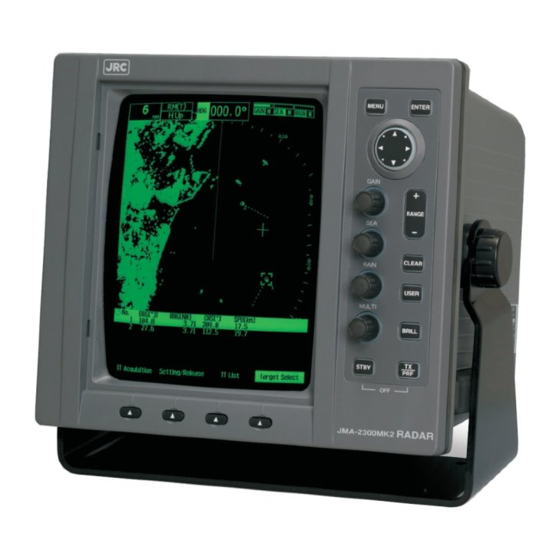
EQUIPMENT APPEARANCE EQUIPMENT APPEARANCE Scanner Unit Type NKE-2043 (2 feet) Scanner Unit Type NKE-2063 (3.9 feet) NCD-2237 Display Unit... -
Page 17: Table Of Contents
CONTENTS CONTENTS PREFACE .................v BEFORE OPERATION .............vi PRECAUTIONS ...............vii WARNING LABEL MOUNTING POINT ........xi EQUIPMENT APPEARANCE ..........xiv GLOSSARY ................xix Chapter 1 GENERAL AND EQUIPMENT COMPOSITION ................1-1 FUNCTIONS..........................1-1 FEATURES ..........................1-2 CONFIGURATION ........................1-3 EXTERIOR DRAWINGS......................1-5 GENERAL SYSTEM DIAGRAMS ................... 1-8 Chapter 2 OPERATIONS............ - Page 18 CONTENTS 2.7.7 DISPLAYING THE RADAR ALARM AND AUTOMATIC ACQUISITION OPERATIONS ............2-44 2.7.8 SETTING DISPLAY BRILLIANCE ................. 2-50 2.7.9 ADJUSTING SCANNER ....................2-51 2.7.10 SETTING DISPLAY SCREEN ..................2-53 2.7.11 SWITCHING TO TRUE/RELATIVE MOTION DISPLAY MODE ........2-57 2.7.12 SWITCHING BEARING DISPLAY MODE..............2-59 2.7.13 SELECTING TRANSMITTER PULSE LENGTH............
-
Page 19: Chapter 3 True And False Echoes On Display
CONTENTS 2.13.6 SETTING AIS DISPLAY TARGET................. 2-98 2.13.7 SETTING AIS DESTINATION SHIP (DirecTrak ) ............2-98 2.13.8 SETTING AIS RETRIEVED VESSEL................2-99 2.13.9 SETTING AIS FILTER....................2-100 2.13.10 TT Target All Clear......................2-100 2.14 SETTING DETECTION LEVELS OF RADAR ALARM ............2-101 2.15 PLOTTER UNIT ........................ - Page 20 CONTENTS 4.3.8 SELF TEST ........................4-12 REPLACEMENT OF MAJOR PARTS .................. 4-16 FAULT FINDING ........................4-17 4.5.1 LIST OF ALARMS AND OTHER INDICATIONS ............4-17 4.5.2 FUSE CHECKING ......................4-24 TROUBLE SHOOTING......................4-25 4.6.1 INCLUDED ACCESSORIES..................4-25 4.6.2 SPECIAL PARTS......................4-27 4.6.3 CIRCUIT BLOCK TO BE REPAIRED................
-
Page 21: Glossary
GLOSSARY GLOSSARY This section describes the main terms used for this equipment and general related maritime terms. Acquisition/Activation zone A zone set up by the operator in which the system should automatically acquire radar targets and activate reported AIS targets when entering the zone. Activated target A target representing the automatic or manual activation of a sleeping target for the display of additional information. - Page 22 GLOSSARY Electronic Bearing Line An electronic bearing line originated from own ship’s position. Enhance Estimated Time of Arrival Ground stabilization A display mode in which speed and course information are referred to the ground, using ground track input data. Heading The horizontal direction that the bow of a ship is pointing at any instant, expressed in angular units from a reference direction .
- Page 23 GLOSSARY Parallel Index line Past positions Equally time-spaced past position marks of a tracked or AIS target and own ship. POSN Position Pulse Repetition Frequency The number of radar pulses transmitted each second. PROC Process Radar signal processing function Radar beacon A navigation aid which responds to the radar transmission by generating a radar signal to identify its position and identity Radar cross-section Radar cross-section of a target determines the power density returned to the radar for a...
- Page 24 GLOSSARY SART Search And Rescue Transponder Radar transponder capable of operating in the 9GHz band Sea stabilization A display mode in which speed and course information are referred to the sea. Sea state Status of the sea condition due to the weather environment, expressed as a sea state 0 for flat conditions with minimal wind, to sea state 8 for very rough sea conditions.
- Page 25 GLOSSARY Universal Time Coordinated. The international standard of time, kept by atomic clocks around the world. Variable Range Marker An adjustable range ring used to measure the distance to a target. Waypoint A geographical location on a route indicating an event. xxiii...
- Page 26 GLOSSARY xxiv...
-
Page 27: Chapter 1 General And Equipment Composition
Chapter 1 GENERAL AND EQUIPMENT COMPOSITION 1.1 FUNCTIONS Chapter 1 GENERAL AND EQUIPMENT COMPOSITION 1.1 FUNCTIONS This equipment is a marine radar equipment consisting of a scanner unit and an integrated monochrome CRT display unit. Function of This System ... -
Page 28: Features
Chapter 1 GENERAL AND EQUIPMENT COMPOSITION 1.2 FEATURES 1.2 FEATURES Easy Operation with the Soft keys and the Multi Control Simple and easy operations are provided so that you can operate without this instruction manual. Target Detection by Latest Signal Processing Technology The system employs a signal processing technology of DSP to eliminate undesired clutter, thus improving the target detection. -
Page 29: Configuration
Chapter 1 GENERAL AND EQUIPMENT COMPOSITION 1.3 CONFIGURATION 1.3 CONFIGURATION Radar Configuration and Ship's Mains RADAR MODEL Scanner Display Unit SHIP'S MAINS JMA-2353 NKE-2043 NCD-2237 12/24 VDC JMA-2354 NKE-2063 Scanners and Transmitted Output Powers TRANSMITTED RATE OF SCANNER TYPE OUTPUT... - Page 30 Chapter 1 GENERAL AND EQUIPMENT COMPOSITION 1.3 CONFIGURATION Included accessories PRODUCT NAME/MODEL QUANTITY JRC CODE REMARKS Fuse (For DC24V/DC32V) 3.15A ULTSC3.15AN1 Fuse (For DC12V) 6.3A ULTSC6.3AN1 Fuse 7ZXRD0031 (For spare for scanner unit) 10A ULTSC10AN1 Connector LTWBD-06FFA-ll7001 Connector LTWBD-08FFA-ll7001 Option...
-
Page 31: Exterior Drawings
Chapter 1 GENERAL AND EQUIPMENT COMPOSITION 1.4 EXTERIOR DRAWINGS 1.4 EXTERIOR DRAWINGS Fig. 1.4-1 Exterior Drawing of Scanner Unit, Type NKE-2043... - Page 32 Chapter 1 GENERAL AND EQUIPMENT COMPOSITION 1.4 EXTERIOR DRAWINGS Fig. 1.4-2 Exterior Drawing of Scanner Unit, Type NKE-2063...
- Page 33 Chapter 1 GENERAL AND EQUIPMENT COMPOSITION 1.4 EXTERIOR DRAWINGS Fig. 1.4-3 Exterior Drawing of Display Unit, Type NCD-2237...
-
Page 34: General System Diagrams
Chapter 1 GENERAL AND EQUIPMENT COMPOSITION 1.5 GENERAL SYSTEM DIAGRAMS 1.5 GENERAL SYSTEM DIAGRAMS Fig. 1.5-1 General System Diagram of Radar Reference: Install the radar cable as far as from the cables of other radio equipment in order to prevent other radio equipment from interfering with the radar operations. -
Page 35: Chapter 2 Operations
Chapter 2 OPERATIONS 2.1 SCREEN DISPLAY OPERATIONS Chapter 2 2.1 SCREEN DISPLAY... -
Page 36: Panel
Chapter 2 OPERATIONS 2.2 PANEL 2.2 PANEL Operate this equipment with the panel of the Display unit. Description Press: Opens/closes the menu. MENU ① Hold down: Opens the code input screen (the Adjust Menu). ② Press: Enters the selected menu item. Press: Selects menu items. - Page 37 Chapter 2 OPERATIONS 2.2 PANEL Key Operations Press: Press a key, then release the key before 2 seconds elapse. Hold down: Press a key, and hold down the key for 2 seconds or more. Press multiple keys: Press multiple keys simultaneously. Turn: Turn a control in clockwise/counterclockwise direction.
-
Page 38: Power On/Off
Chapter 2 OPERATIONS 2.3 POWER ON/OFF 2.3 POWER ON/OFF CAUTION A malfunction may occur if the power in the ship is instantaneously interrupted during operation of the radar. In this case, the power should be turned on again. Note: Wait for about 2 seconds before turning on the power again. ... - Page 39 Chapter 2 OPERATIONS 2.3 POWER ON/OFF Starting transmission 1 Press the [TX/PRF] key. The radar starts transmission and the antenna starts rotating. Reference: The radar cannot start transmission if you press the [TX/PRF] key while the preheating time is displayed. ...
-
Page 40: Sensitivity Adjustment
Chapter 2 OPERATIONS 2.4 SENSITIVITY ADJUSTMENT 2.4 SENSITIVITY ADJUSTMENT Sensitivity can be adjusted. Adjust the noise on the display unit to achieve better observation state. CAUTION If sensitivity is set too high, unnecessary signals such as noises in the receiver and false echoes increase to lower target visibility. At the same time, if sensitivity is set too low, detection of targets such as ships and dangerous objects may be hindered. - Page 41 Chapter 2 OPERATIONS 2.4 SENSITIVITY ADJUSTMENT [GAIN] Control Turning the [GAIN] control clockwise increases receiving sensitivity and extends the radar observation range. If the sensitivity is too high, the receiver noise increases reducing the contrast between the targets and the background video. As a result, the targets become obscure on the radar display.
-
Page 42: Sea Clutter Suppression
Chapter 2 OPERATIONS 2.5 SEA CLUTTER SUPPRESSION 2.5 SEA CLUTTER SUPPRESSION The sea clutter suppression function suppresses sea clutter returns. CAUTION When using the sea clutter suppression function, never set the suppression level too high canceling out all image noises from the sea surface at close range. - Page 43 Chapter 2 OPERATIONS 2.5 SEA CLUTTER SUPPRESSION [SEA] Control The sea clutter suppression function suppresses sea clutter returns by decreasing the receiving sensitivity on a short range. Turn the [SEA] control clockwise to heighten the effect of sea clutter suppression. However, be careful that excessive suppression causes low signal-strength targets such as buoys and boats to disappear from the radar display.
- Page 44 Chapter 2 OPERATIONS 2.5 SEA CLUTTER SUPPRESSION Canceling Automatic Sea Clutter Suppression Function 1 Hold down the [SEA] control. Automatic function is canceled. The mode is indicated as shown below. Reference: When the automatic mode is selected for the sea clutter suppression function, the rain/snow clutter suppression function is switched to the manual mode.
-
Page 45: Rain/Snow Clutter Suppression
Chapter 2 OPERATIONS 2.6 RAIN/SNOW CLUTTER SUPPRESSION 2.6 RAIN/SNOW CLUTTER SUPPRESSION This function suppresses rain/snow clutter returns. CAUTION When using the sea clutter suppression function, never set the suppression level too high canceling out all image noises from the rain or snow at close range. Detection of not only echoes from the rain or snow but also targets such as other ships or dangerous objects will become inhibited. - Page 46 Chapter 2 OPERATIONS 2.6 RAIN/SNOW CLUTTER SUPPRESSION [RAIN] Control When the [RAIN] control is turned clockwise, targets hidden by rain/snow clutter returns appear on the radar display. However, be careful that excessive suppression may cause small targets to be overlooked. Since the rain/snow clutter suppression function also has the effect of suppressing sea clutter, the suppression efficiency improves when using with the [SEA] control.
- Page 47 Chapter 2 OPERATIONS 2.6 RAIN/SNOW CLUTTER SUPPRESSION Switching to Manual/Automatic Mode 1 Hold down the [RAIN] control. Automatic function is canceled. The mode is indicated as shown below. Reference: When the automatic mode is selected for the rain/snow clutter suppression function, the sea clutter suppression function is switched to the manual mode.
-
Page 48: Soft Key Operation
Chapter 2 OPERATIONS 2.7 SOFT KEY OPERATION 2.7 SOFT KEY OPERATION This radar can be operated with the soft keys and the MULTI control placed on the front panel of the display unit. You can access to functions without opening the menu screen. To change the default settings, press the [MENU] key to open the menu screen. - Page 49 Chapter 2 OPERATIONS 2.7 SOFT KEY OPERATION 1 Press the [[MULTI] control. Press the [MULTI] control. 2 Turn the [MULTI] control to select Display Screen on the soft key menu. "Display Screen" is color-inverted. Reference: When a certain time elapses without any key operation after selecting an item on the soft key menu, the soft key menu and the soft key display automatically disappear.
- Page 50 Chapter 2 OPERATIONS 2.7 SOFT KEY OPERATION Turning the [MULTI] control clockwise To select "Own Track" - "TLL TX" "Event Mark" is color-inverted. "Own Track" is color-inverted. ▼ "TLL TX" is color-inverted. "AIS Filter" is color-inverted. Reference: When the item at the bottom of the soft key menu is color-inverted, the soft key menu does not scroll any more even if the control is turned clockwise.
- Page 51 Chapter 2 OPERATIONS 2.7 SOFT KEY OPERATION Turning the [MULTI] control counterclockwise To select "VRM2" - "EBL1" "VRM1" is color-inverted. "VRM2" is color-inverted. ▼ "EBL1" is color-inverted. "EBL2" is color-inverted. Reference: When the item at the top of the soft key menu is color-inverted, the soft key menu does not scroll any more even if the control is turned counterclockwise.
- Page 52 Chapter 2 OPERATIONS 2.7 SOFT KEY OPERATION Soft key 1 "Screen 1" is color-inverted. Press the [soft key 1]. The screen changes to the layout set in the section "4.13.7 LOCATION CHANGE" - "1. Screen1". Soft key 2 "Screen 2"...
- Page 53 Chapter 2 OPERATIONS 2.7 SOFT KEY OPERATION Closing the soft key menu Press the [CLEAR] key to turn off the soft key menu and the soft key display. Soft keys 1, 2, 3 and 4 Press any of the soft keys. If any of the soft keys is pressed when the soft key menu is turned off, the soft key menu and the soft key display which were displayed previously appear again.
- Page 54 Chapter 2 OPERATIONS 2.7 SOFT KEY OPERATION 1 Press a soft key. Press the [MULTI] control. 2 Turn the [MULTI] control to select Brilliance on the soft key menu. Select "Brilliance" and press the control. "Brilliance" is activated. Reference: Perform the same operations for the other soft key menu items to activate the functions. ...
- Page 55 Chapter 2 OPERATIONS 2.7 SOFT KEY OPERATION Soft key 2 "Monitor BRILL" is color-inverted. Press the [soft key 2]. "Monitor BRILL" is color-inverted, and is activated. Press the [BRILL] key to adjust at eight levels. Soft key 3 "Panel BRILL"...
-
Page 56: Measuring Target Bearing (Ebl)
Chapter 2 OPERATIONS 2.7 SOFT KEY OPERATION Soft keys 1, 2, 3 and 4 Press any of the soft keys. If any of the soft keys is pressed when the soft key menu is turned off, the soft key menu and the soft key display which were displayed previously appear again, and the function is activated. - Page 57 Chapter 2 OPERATIONS 2.7 SOFT KEY OPERATION 2 Operate with the soft keys. Soft key 1: Display Off Display "Display Off": "EBL1"/"EBL2" is not displayed. "Display": "EBL1"/"EBL2" is displayed. Reference: When "Display Off" is selected for the soft key 1, the equipment performs the followings: ...
-
Page 58: Measuring Range To Target (Vrm)
Chapter 2 OPERATIONS 2.7 SOFT KEY OPERATION Soft key 4: BRG Operation When "EBL1" or "EBL2" of the soft key menu is selected, "BRG Operation" of the soft key display is color-inverted. Turn the [MULTI] control to change the direction of "EBL1"/"EBL2". To determine the setting of "EBL1"/"EBL2", press one of the followings: the [MULTI] control, the soft key 4 or the [CLEAR] key. - Page 59 Chapter 2 OPERATIONS 2.7 SOFT KEY OPERATION Select "VRM2" and press the control. When "VRM1" is selected, the soft key menu is turned off and "DIST Operation" of the soft key display is color-inverted. "VRM2" is activated. 2 Operate with the soft keys. Soft key 1: Display Off Display "Display Off": "VRM1"/"VRM2"...
-
Page 60: Setting Vectors
Chapter 2 OPERATIONS 2.7 SOFT KEY OPERATION Variable Range Marker VRM1 is represented as a broken line, and VRM2 as a dotted line. When EBL1 is displayed, VRM1 marker appears on the EBL1. When EBL2 is displayed, VRM2 marker appears on the EBL2. - Page 61 Chapter 2 OPERATIONS 2.7 SOFT KEY OPERATION 1 Select Vector Length on the soft key menu. Select "Vector Length" and press the control. The soft key menu disappears and "Vector Length" of the soft key display is color-inverted. "Vector Length" is activated. 2 Operate with the soft keys.
-
Page 62: Vector Modes
Chapter 2 OPERATIONS 2.7 SOFT KEY OPERATION A vector to represent a target's predicted position can presented in the True vector or Relative vector mode. In each mode, a vector length can be freely changed for a time interval of 1 to 60 minutes. ... -
Page 63: Displaying Other Ship's Tracks (Radar Trails)
Chapter 2 OPERATIONS 2.7 SOFT KEY OPERATION Vector Length The vector length of a target is proportional to its speed, and the vector time can be switched in a range of 1 to 60 minutes. The diagram below illustrates a vector length of a target for six minutes, and the tip of the vector represents the target's position expected to reach six minutes later. - Page 64 Chapter 2 OPERATIONS 2.7 SOFT KEY OPERATION 2 Operate with the soft keys. Soft key 1: REF Level1 REF Level2 REF Level3 REF Level4 Selects a radar video level required for plotting radar trails. "REF Level1" is the lowest level while "REF Level4" is the highest level. ...
-
Page 65: Ais Operations
Chapter 2 OPERATIONS 2.7 SOFT KEY OPERATION Reference: When "RADAR Trails" is not selected on the soft key menu, press the soft key 4 to activate the RADAR Trails function. The time for "Trails" changes as shown below. Off/15sec/30sec/1min/2min/3min/4min/5min/6min/10min/15min/All 2.7.5 AIS OPERATIONS The AIS function shows the target's information on the radar display, using other ship's information sent out from the AIS unit. - Page 66 Chapter 2 OPERATIONS 2.7 SOFT KEY OPERATION Soft key 3: AIS List AIS Number SEL "AIS List": AIS list is displayed. "AIS Number SEL": AIS list is not displayed. Soft key 4: Target Select When "AIS" of the soft key menu is selected, "Target Select" of the soft key display is color-inverted.
- Page 67 Chapter 2 OPERATIONS 2.7 SOFT KEY OPERATION Note: Numerical Data, AIS retrieved vessel and AIS destination ship can be operated when Soft key 1: Numerical Data Retrieved Vessel DEST Ship are selected. Displaying AIS data (Operation with the [ENT] key) AIS data (numerical display) can be done by the [ENT] key operation without displaying the soft key menu.
- Page 68 Chapter 2 OPERATIONS 2.7 SOFT KEY OPERATION Displaying the other AIS data Reference: AIS retrieved vessel can be set by specifying MMSI number. For details of settings, see "2.13.8 SETTING AIS RETRIEVED VESSEL". AIS destination ship can be set by specifying MMSI number. For details of settings, see "2.13.7 SETTING AIS DESTINATION SHIP".
- Page 69 Chapter 2 OPERATIONS 2.7 SOFT KEY OPERATION When the AIS destination ship is set, "$" is displayed in the AIS list. "$" disappears when it is released. Reference: AIS data (Numerical Data) is displayed when the soft key 4 is set to "AIS Detail" in the section "2.7.10 SETTING DISPLAY SCREEN"...
-
Page 70: Tt Operations
Chapter 2 OPERATIONS 2.7 SOFT KEY OPERATION Setting AIS Symbol Display For details of displaying/hiding of the AIS symbols, see Section "2.7.15 SETTING SYMBOL ". 2.7.6 TT OPERATIONS The target tracking function calculates the course and speed of a target by automatically tracking the target's move. - Page 71 Chapter 2 OPERATIONS 2.7 SOFT KEY OPERATION CAUTION Use the radar only as a navigation aid. The final navigation decision must always be made by the operator him/herself. Making the final navigation decision based only on the radar display may cause accidents such as collisions or running aground. Use the target tracking function (TT) only as a navigation aid.
- Page 72 Chapter 2 OPERATIONS 2.7 SOFT KEY OPERATION Soft key 2: Setting/Release Target tracking data (numerical display) can be set/released. Soft key 3: TT List TT Number SEL "TT List": TT list is displayed. "TT Number SEL": TT list is not displayed. Soft key 4: Target Select When "TT"...
- Page 73 Chapter 2 OPERATIONS 2.7 SOFT KEY OPERATION Reference: When the number of targets tracked has reached to the maximum (10 targets), any new target is not acquired. Delete the unnecessary targets, then acquire new targets. Manual acquisition (Operation with the [ENT] key) Target can be acquired by the [ENT] key operation without displaying the soft key menu.
- Page 74 Chapter 2 OPERATIONS 2.7 SOFT KEY OPERATION Reference: If untracked targets intrude into the automatic acquisition area in the conditions that maximum number of targets (10 targets) is under tracking, the targets acquired automatically will be cancelled in the order of lower levels of danger. ...
- Page 75 Chapter 2 OPERATIONS 2.7 SOFT KEY OPERATION Reference: If a target with the mark “○” is designated, only its true bearing and range will appear until its vector appears. Tracking target data is displayed when the soft key 4 is set to "TT Detail" in the section "2.7.10 SETTING DISPLAY SCREEN"...
- Page 76 Chapter 2 OPERATIONS 2.7 SOFT KEY OPERATION Displaying the other tracking target data Note: The numerical display can be operated when Soft key 4: Target Select are selected. Displaying tracking target data 1 Turn the [MULTI] control to select the target for the numerical display, then press the soft key 3 "Setting/Release".
- Page 77 Chapter 2 OPERATIONS 2.7 SOFT KEY OPERATION Target Tracking Symbols This section describes types and definitions of target tracking symbols. Symbol Definition Remarks Initial acquisition This symbol is displayed where the target is acquired. This is displayed with a circle of thin dotted line. This symbol is also used for the target acquired automatically.
-
Page 78: Displaying The Radar Alarm And Automatic Acquisition Operations
Chapter 2 OPERATIONS 2.7 SOFT KEY OPERATION 2.7.7 DISPLAYING THE RADAR ALARM AND AUTOMATIC ACQUISITION OPERATIONS With a fan-shaped range made, the radar alarm can give an alarm to ships that enter or depart from the range. Reference: "Alarm2" is initially set to off. To use this function, set this to on by referring to "■ Soft Key Menu Setting"... - Page 79 Chapter 2 OPERATIONS 2.7 SOFT KEY OPERATION 2 Operate with the soft keys. Soft key 1: When Alarm1 is selected When Alarm2 is selected Turns on/off the alarm display. Soft key 2: When Alarm1 is selected Sector Rectangle When Alarm2 is selected Sector Rectangle "Sector":...
- Page 80 Chapter 2 OPERATIONS 2.7 SOFT KEY OPERATION Automatic acquisition operations Reference: If untracked targets intrude into the acquisition area in the conditions that maximum number of targets (10 targets) is under tracking, the targets acquired automatically will be cancelled in the order of lower levels of danger. ...
- Page 81 Chapter 2 OPERATIONS 2.7 SOFT KEY OPERATION Creating a fan-shaped radar alarm/acquisition area 1 Perform the following settings. Soft key 2: When Alarm1 is selected Sector When Alarm2 is selected Sector The range setting is started for a fan-shaped radar alarm/acquisition area. 2 Press the cursor keys to move the cursor to the first point (setting of the start bearing and range), then press the [ENT] key.
- Page 82 Chapter 2 OPERATIONS 2.7 SOFT KEY OPERATION 4 Press the cursor keys to move the cursor to the third point (setting of the end bearing), then press the [ENT] key. 5 A fan-shaped radar alarm/acquisition area is determined. Reference: After the fan-shaped radar alarm/acquisition area is determined, the soft key menu and the soft key display disappears, and Alarm1 function is terminated.
- Page 83 Chapter 2 OPERATIONS 2.7 SOFT KEY OPERATION 2 Press the cursor keys to move the cursor to the first point (setting of the start latitude and longitude), then press the [ENT] key. 3 Press the cursor keys to move the cursor to the second point (setting of the end latitude), then press the [ENT] key.
-
Page 84: Setting Display Brilliance
Chapter 2 OPERATIONS 2.7 SOFT KEY OPERATION 5 Rectangle-shaped area Rectangle-shaped area is set with Nup as reference. Reference: After the fan-shaped radar alarm/acquisition area is determined, the soft key menu and the soft key display disappears, and Alarm1 function is terminated. 2.7.8 SETTING DISPLAY BRILLIANCE Display brilliance can be changed. -
Page 85: Adjusting Scanner
Chapter 2 OPERATIONS 2.7 SOFT KEY OPERATION Reference: In the factory setting, "Soft Key" menu items for "Day2", "Day3", "Dusk" and "Night" are set to "Off" in "Main Menu" - "Brilliance". To use these, set the items to "On". Soft key 2: Monitor BRILL Press the soft key 2 to adjust Monitor BRILL at eight levels. - Page 86 Chapter 2 OPERATIONS 2.7 SOFT KEY OPERATION Soft key 2: Manual Tuning When pressing the soft key 2, "Manual Tuning" is color-inverted. When "MAN" is displayed above the soft key 1 You can manually adjust using the MULTI control. Tune indicator bar Turn the MULTI control to adjust tuning.
-
Page 87: Setting Display Screen
Chapter 2 OPERATIONS 2.7 SOFT KEY OPERATION 2.7.10 SETTING DISPLAY SCREEN Sets the layout of radar screen. 1 Select Display Screen on the soft key menu. "Display Screen" is color-inverted. The "Display Screen" soft key display appears. 2 Operate with the soft keys. Soft key 1: Screen1 The screen changes to the layout set with the menu "Adjust Menu"... - Page 88 Chapter 2 OPERATIONS 2.7 SOFT KEY OPERATION Numerical INFO If "Screen1" has been set in the menu When "Numerical INFO" is displayed above the soft key 4, "Numerical INFO" which has been set in the menu "Screen 1" is displayed. Numerical INFO If "Screen2"...
- Page 89 Chapter 2 OPERATIONS 2.7 SOFT KEY OPERATION TT Detail When "Numerical INFO" is displayed above the soft key 4, press the soft key 4 to display "TT Detail" on the radar screen. TT Detail AIS Detail When "TT Detail" is displayed above the soft key 4, press the soft key 4 to display "AIS Detail"...
- Page 90 Chapter 2 OPERATIONS 2.7 SOFT KEY OPERATION Own AIS INFO When "AIS Detail" is displayed above the soft key 4, press the soft key 4 to display "Own AIS INFO" on the radar screen. Own AIS INFO MOB INFO When "Own AIS INFO"...
-
Page 91: Switching To True/Relative Motion Display Mode
Chapter 2 OPERATIONS 2.7 SOFT KEY OPERATION Hiding the heading line 1 Hold down the [TX/PRF] key. The ship's heading line is hidden while the [TX/PRF] key is held down. The ship's heading line (HL) that presents the course of own ship is always shown on the radar display. - Page 92 Chapter 2 OPERATIONS 2.7 SOFT KEY OPERATION 2 Operate with the soft keys. Soft key 1: RM Press the soft key 1 to switch to relative motion display. Own ship returns to the center of the radar screen. Soft key 2: TM Press the soft key 2 to switch to true motion display.
-
Page 93: Switching Bearing Display Mode
Chapter 2 OPERATIONS 2.7 SOFT KEY OPERATION 2.7.12 SWITCHING BEARING DISPLAY MODE Selects the azimuth of the radar video. Reference: The bearing signal input is required to display N Up/C Up. 1 Select Bearing Mode on the soft key menu. "Bearing Mode"... - Page 94 Chapter 2 OPERATIONS 2.7 SOFT KEY OPERATION Relative Bearing Mode The video is displayed so that the ship's heading line points to the zenith of the PPI (0° on range rings). Since targets are displayed in their directions relative to the ship's heading line, the operator can view the video in the same field of view as in operating the ship at sea.
-
Page 95: Selecting Transmitter Pulse Length
Chapter 2 OPERATIONS 2.7 SOFT KEY OPERATION Course-up Bearing Mode By pressing the soft key 3, the own ship's course is fixed pointing to the zenith of the PPI (0° on range rings) points to the due north. In the same way as in the North-up mode, fixed targets do not flicker, and are stabilized even if the ship is yawing. - Page 96 Chapter 2 OPERATIONS 2.7 SOFT KEY OPERATION Reference: Options of the transmitter pulse length vary depending on the range. For details, see "7.2 SCANNER". Soft key 2: Not available Soft key 3: Not available Soft key 4: Not available Effects of transmitter pulse length ...
-
Page 97: Moving Own Ship's Display Position
Chapter 2 OPERATIONS 2.7 SOFT KEY OPERATION 2.7.14 MOVING OWN SHIP’S DISPLAY POSITION The own ship's position can be moved from the display center to any position within 66% of the display radius. This function is convenient for observing a wide coverage in any direction. 1 Select Off Center on the soft key menu. -
Page 98: Setting Symbol Display
Chapter 2 OPERATIONS 2.7 SOFT KEY OPERATION Soft key 3: Save Position When "Custom" is displayed above the soft key 2, press the soft key 3 to save the current own ship’s display position. Soft key 4: Edit When "Custom" is displayed above the soft key 2, press the soft key 4 to move the own ship’s display position to any position. -
Page 99: Setting Mob
Chapter 2 OPERATIONS 2.7 SOFT KEY OPERATION Soft key 3: Mark Display Mark DISP Off "Mark Display": The marks and lines are displayed. "Mark DISP Off": The marks and lines are hidden. Soft key 4: Track Display Track DISP Off "Track Display": The own track is displayed. -
Page 100: Marking
Chapter 2 OPERATIONS 2.7 SOFT KEY OPERATION 2.7.17 MARKING Marks can be indicated at arbitrary positions on the screen. A mark created on the screen holds the latitude and longitude. Reference: Bearing signal input and latitude/longitude data input are required to use marks. ... -
Page 101: Using Lines
Chapter 2 OPERATIONS 2.7 SOFT KEY OPERATION Soft key 4: Off Enter Erase Move You can use the [ENT] key to create/delete/move the marks. "Enter": Press the [ENT] key to create a mark at the cursor position. "Erase": Press the [ENT] key to delete a mark at the cursor position. "Move": Use the cursor to select the mark to be moved and press the [ENT] key. -
Page 102: Displaying Own Ship's Track
Chapter 2 OPERATIONS 2.7 SOFT KEY OPERATION Soft key 4: Off Enter Erase Move Insert You can use the [ENT] key to create/delete/move the lines. "Enter": Press the [ENT] key to create a line at the cursor position. "Erase": Press the [ENT] key to delete a line at the cursor position. "Move": Use the cursor to select the line to be moved and press the [ENT] key. -
Page 103: Using Event Marks
Chapter 2 OPERATIONS 2.7 SOFT KEY OPERATION Soft key 3: 3sec 5sec 10sec 30sec 1min 3min 5min 10min 30min 60min 10NM The storage interval of the own ship's track is changed. A preset time interval or preset distance interval can be selected as the storage interval. The distance setting varies depending on the range scale unit setting. -
Page 104: Setting Ais Filter
Chapter 2 OPERATIONS 2.7 SOFT KEY OPERATION Soft key 3: Delete Press to delete the marks of selected type. Hold down to delete all marks. The confirmation dialog window is displayed. (Marks and event marks are not distinguished when deleting.) Soft key 4: Event Mark ENT An event mark is placed at the own ship's position. -
Page 105: Using Tll Tx
Chapter 2 OPERATIONS 2.7 SOFT KEY OPERATION 2 Operate with the soft keys. Soft key 1: Off Range Switches between Off and Range.. "Range": A filter is set in a circle with a set range as the radius. Soft key 2: Off "Off": The filter is not displayed. -
Page 106: Basic Menu Operations
Chapter 2 OPERATIONS 2.8 BASIC MENU OPERATIONS 2.8 BASIC MENU OPERATIONS The settings which will not be frequently changed are called by the [MENU] key. This section describes the operation with the MENU key. Keys for operation [MENU] key ... - Page 107 Chapter 2 OPERATIONS 2.8 BASIC MENU OPERATIONS 2 Press the cursor key (down) or turn the [MULTI] control (clockwise) to select RADAR Echo . "RADAR Echo" is color-inverted. 3 Press the [ENT] key, the cursor key (right) or the [MULTI] control. "RADAR Echo"...
- Page 108 Chapter 2 OPERATIONS 2.8 BASIC MENU OPERATIONS 4 Press the cursor key (down) or turn the [MULTI] control (clockwise) to select IR . "IR" is color-inverted. 5 Press the [ENT] key, the cursor key (right) or the [MULTI] control. The current setting is color-inverted. "IR"...
- Page 109 Chapter 2 OPERATIONS 2.8 BASIC MENU OPERATIONS 6 Select the desired item, then press the [ENT] key or the [MULTI] control. Select the desired item. 7 The setting is determined and displayed. Setting is determined. Closing the menu Repeatedly press the [CLEAR] key or the cursor key (left) to return to the upper level and then close the menu screen.
-
Page 110: Radar Echo Settings
Chapter 2 OPERATIONS 2.9 RADAR ECHO SETTINGS 2.9 RADAR ECHO SETTINGS This function enables the setting of detail information about radar echo. "RADAR Echo" operations 1 Open RADAR Echo from the Main Menu. "RADAR Echo" menu appears. Detail information about radar signal processing can be set by changing the settings of the menu items. -
Page 111: Setting For Enhancing Targets
Chapter 2 OPERATIONS 2.9 RADAR ECHO SETTINGS When a high interference rejection level is selected, the radar's ability of detecting small targets such as buoys and small boats lowers. In general, Low should be selected. 2.9.2 SETTING FOR ENHANCING TARGETS ... -
Page 112: Process
Chapter 2 OPERATIONS 2.9 RADAR ECHO SETTINGS 2.9.3 PROCESS Process This function reduces unnecessary noise to highlight targets. Note: When viewing a radar beacon, SART signal, or fast moving target on the radar display, do not use this function. ... -
Page 113: Zooming
Chapter 2 OPERATIONS 2.9 RADAR ECHO SETTINGS Note: When "COREL" is set, the image becomes smaller. When "Remain" or "Peak Hold" is set, the afterimage will appears. 2.9.4 ZOOMING Zooming This function doubles the size of radar video. 1 Open RADAR Echo Zoom . -
Page 114: Video Noise Rejection
Chapter 2 OPERATIONS 2.9 RADAR ECHO SETTINGS Video Latitude Select Normal in standard, and Wide1 in rainy weather. Narrow clearly displays short-range videos when STC is used in manual mode. 2.9.6 VIDEO NOISE REJECTION Video Noise Rejection This function rejects signals that assumed as noise and clutter in radar videos. 1 Open RADAR Echo Video Noise Rejection . -
Page 115: Marker Setting
Chapter 2 OPERATIONS 2.10 MARKER SETTING 2.10 MARKER SETTING Sets operations for EBLs, parallel cursors, cursors and range rings. "Marker" operations 1 Open Marker from the Main Menu. "Marker" menu appears. 2.10.1 SETTING OPERATIONS FOR EBLS (ELECTRONIC BEARING LINES) ... - Page 116 Chapter 2 OPERATIONS 2.10 MARKER SETTING Setting the mode to move the starting point of EBL (Floating setting) Reference: Course and latitude/longitude data input is required for floating setting. The heading and latitude/longitude input are not required during floating (Screen FIX). When this function is set to L/L Fix and the starting point of an EBL is moved to a position, the starting point can be fixed at the latitude and longitude of that position.
-
Page 117: Setting Cursors
Chapter 2 OPERATIONS 2.10 MARKER SETTING 2.10.2 SETTING CURSORS This function enables the setting of detail information about cursor display. "Cursor" operations 1 Open Marker - Cursor . "Cursor" menu appears. Cursor Length Sets the length of the cross cursor mark on the radar display. 1 Open Cursor Cursor Length . -
Page 118: Setting Range Rings
Chapter 2 OPERATIONS 2.10 MARKER SETTING Distance Unit Sets the distance unit for cursor. 1 Open Cursor Distance Unit . NM : The distance unit is set to NM. km : The distance unit is set to km. sm : The distance unit is set to sm. -
Page 119: Brilliance
Chapter 2 OPERATIONS 2.11 BRILLIANCE 2.11 BRILLIANCE This function enables the setting of detail information about radar display. "Brilliance" operations 1 Open Brilliance from the Main Menu. "Brilliance" menu appears. Setting each items Sets the brilliance of each item. ... - Page 120 Chapter 2 OPERATIONS 2.11 BRILLIANCE Keyboard Unit Brilliance Adjusts the brilliance of operation panel. "Keyboard Unit Brilliance" menu appears. Brilliance Adjusts the brilliance of operation panel. "Brilliance" menu appears. 2-86...
-
Page 121: Control Setting
Chapter 2 OPERATIONS 2.12 CONTROL SETTING 2.12 CONTROL SETTING This function enables the setting of detail information about radar echo. "Control" operations 1 Open Control from the Main Menu. "Control" menu appears. 2.12.1 DISPLAYING TRUE/RELATIVE MOTION Sets the bearing standards for the cursor, TT, AIS and MOB. Reference: Bearing signal input is required to display true motion. -
Page 122: Setting User Keys
Chapter 2 OPERATIONS 2.12 CONTROL SETTING 2.12.2 SETTING USER KEYS Users can freely assign functions to the user keys. When using this function, you can instantly open the menu screen of "VRM1 Unit", "VRM2 Unit", "Alarm" and "Display". "User Key" operations 1 Open Control - User Key . -
Page 123: Adjusting Buzzer Volume
Chapter 2 OPERATIONS 2.12 CONTROL SETTING Using user keys Operates as user keys. Displaying the menu assigned to the user key1 Press the [USER] key. 2.12.3 ADJUSTING BUZZER VOLUME When an alarm goes off, the operation panel of the equipment produces a sound to notify users of state changes. - Page 124 Chapter 2 OPERATIONS 2.12 CONTROL SETTING "Output Buzzer" operations 1 Open Control - Output Buzzer . "Output Buzzer" menu appears. Setting CPA/TCPA Sets the external buzzer for CPA/TCPA. Off : Sets the external buzzer to Off. On : Sets the external buzzer to On.
-
Page 125: Setting Tt/Ais
Chapter 2 OPERATIONS 2.13 SETTING TT/AIS 2.13 SETTING TT/AIS This section describes the operations of TT and AIS. 2.13.1 COLLISION AVOIDANCE Problems of Collision Avoidance in Navigation Marine collision avoidance is one of the problems that have been recognized from of old. Now, it will be described briefly who the collision avoidance is positioned among the navigational aid problems. - Page 126 Chapter 2 OPERATIONS 2.13 SETTING TT/AIS Marine Accidents and Collisions Among marine accidents, collision accidents have been highlighted as the tonnages and speeds of ships become higher along with the increase in traffic at sea. If a tanker carrying dangerous articles such as crude oil collides with any other vessel, then not only the vessels involved with the accident but other vessels in the vicinity, port facilities, inhabitants in the coastal area as well as marine resources may also suffer immeasurable damages and troubles.
- Page 127 Chapter 2 OPERATIONS 2.13 SETTING TT/AIS Relative Vector and True Vector From two points of view, collision prediction and avoidance, it is necessary to obtain the relative vector of other ship for prediction and the true vector of other ship for collision avoidance in order to grasp other ship's aspect.
-
Page 128: Preparation
Chapter 2 OPERATIONS 2.13 SETTING TT/AIS 2.13.2 PREPARATION Initializes Tracking Target and AIS Function "Target" operations 1 Open Target from the Main Menu. "Target" menu appears. TT Target All Clear All targets currently acquired are cleared. Setting Collision Decision Criteria Set and check collision decision criteria before operating. -
Page 129: Setting Target Number Display
Chapter 2 OPERATIONS 2.13 SETTING TT/AIS Setting CPA Ring Sets the CPA ring display. Off : The CPA ring is not displayed. On : The CPA ring is displayed. While the distance of the specified CPA Limit value is used as the radius, the CPA ring is displayed with a white circle of which center is the own ship's position. -
Page 130: Setting Target Number Allocation
Chapter 2 OPERATIONS 2.13 SETTING TT/AIS Turning On/Off the Number of Tracking Target and AIS Turns on/off the number of tracking target and AIS symbol. 1 Open Target Number Display - TT AIS . Off : Target numbers of TT/AIS are not displayed. On : Target numbers of TT/AIS are displayed. -
Page 131: Setting Ais Alarm
Chapter 2 OPERATIONS 2.13 SETTING TT/AIS Target Number Allocation Turns on/off the start number of target for tracking. 1 Open Target Number Allocation - Own Ship's Cursor . Turn the [MULTI] control to set the start number of target. Operate the same way for the other target numbers. -
Page 132: Setting Ais Display Target
Chapter 2 OPERATIONS 2.13 SETTING TT/AIS 2.13.6 SETTING AIS DISPLAY TARGET Set the number of AIS display targets. Set this to get a better look at the screen by limiting the number of AIS symbols. Setting AIS Display Target 1 Open Target AIS Display Target . -
Page 133: Setting Ais Retrieved Vessel
Chapter 2 OPERATIONS 2.13 SETTING TT/AIS 2.13.8 SETTING AIS RETRIEVED VESSEL AIS retrieved vessel is the function to preferentially display the user-specified ship. If MMSI of AIS target is set, the retrieved vessel can be specified. Reference: AIS retrieved vessel can be set up to 10 vessels. ... -
Page 134: Setting Ais Filter
Chapter 2 OPERATIONS 2.13 SETTING TT/AIS 2.13.9 SETTING AIS FILTER Sets the range for AIS filter. Reference: For details of AIS filter, refer to "2.7.21 SETTING AIS FILTER". Setting AIS Filter 1 Open Target AIS Filter . Turn the [MULTI] control to set the range for AIS filter. The range can be set between 0 and 72.0 NM. -
Page 135: Setting Detection Levels Of Radar Alarm
Chapter 2 OPERATIONS 2.14 SETTING DETECTION LEVELS OF RADAR ALARM 2.14 SETTING DETECTION LEVELS OF RADAR ALARM Detection levels can be set to issue alarms from the radar alarm. Reference: For details of display settings for radar alarm, see "2.7.7 DISPLAYING THE RADAR ALARM AND AUTOMATIC ACQUISITION OPERATIONS". -
Page 136: Plotter Unit
Chapter 2 OPERATIONS 2.15 PLOTTER UNIT 2.15 PLOTTER UNIT Sets the plotter unit. "Plot" operations 1 Open Main Menu - Plot . "Plot" menu appears. 2.15.1 DISPLAYING WAYPOINT MARKS When waypoint information is received from the navigation equipment, the waypoint mark appears on the radar display. -
Page 137: Displaying Own Ship's Track
Chapter 2 OPERATIONS 2.15 PLOTTER UNIT 2.15.2 DISPLAYING OWN SHIP'S TRACK Sets the own ship's track display. "Own Track" operations 1 Open Plot Own Track . "Own Track" menu appears. Clear Own Track Sets to clear the own tracks by specifying color/type. 1 Open Own Track - Clear Own Track . -
Page 138: Setting Timed Tx
Chapter 2 OPERATIONS 2.16 SETTING TIMED TX 2.16 SETTING TIMED TX Sets timed TX function. Timed TX This function reduces power consumption. When using timed TX function, the operation state is repeatedly changed between TX and standby state. The timed TX function can set TX time and standby time as desired. ... - Page 139 Chapter 2 OPERATIONS 2.16 SETTING TIMED TX Setting TX Time Sets the number of antenna rotation. Turn the [MULTI] control to set the TX time. TX time can be adjusted between 0 and 99Scan. Setting Standby Time Sets the time for standby state. Turn the [MULTI] control to set the Standby Time.
- Page 140 Chapter 2 OPERATIONS 2.16 SETTING TIMED TX 2-106...
-
Page 141: Chapter 3 True And False Echoes On Display
Chapter 3 TRUE AND FALSE ECHOES ON DISPLAY 3.1 RADAR WAVE WITH THE HORIZON Chapter 3 TRUE AND FALSE ECHOES ON DISPLAY The radar operator has a role of interpreting the radar displays to provide his best aid in maneuvering the ship. For this purpose, the operator has to observe the radar displays after fully understanding the advantages and disadvantages that the radar has. - Page 142 Chapter 3 TRUE AND FALSE ECHOES ON DISPLAY 3.1 RADAR WAVE WITH THE HORIZON When the height of own ship's scanner is 10 m for instance, (a) A target that can be detected at the radar range of 64 nm on the radar display is required to have a height of 660 m or more.
-
Page 143: Reflection From Target
Chapter 3 TRUE AND FALSE ECHOES ON DISPLAY 3.2 REFLECTION FROM TARGET 3.2 REFLECTION FROM TARGET The signal intensity reflected from a target depends not only on the height and size of the target but also on its material and shape. The echo intensity from a higher and larger target is not always higher in general. -
Page 144: Sea Clutter And Rain And Snow Clutter
Chapter 3 TRUE AND FALSE ECHOES ON DISPLAY 3.3 SEA CLUTTER AND RAIN AND SNOW CLUTTER 3.3 SEA CLUTTER AND RAIN AND SNOW CLUTTER In addition to the echo required for observing ships and land radar video image also includes unnecessary echo, such as reflection from waves on the sea surface and reflection from rain and snow. -
Page 145: False Echoes
Chapter 3 TRUE AND FALSE ECHOES ON DISPLAY 3.4 FALSE ECHOES 3.4 FALSE ECHOES The radar observer may be embarrassed with some echoes that do not exist actually. These false echoes appear by the following causes that are well known: 3.4.1 SHADOW When the radar scanner is installed near a funnel or mast, the echo of a target that exists... -
Page 146: False Echo By Multiple Reflection
Chapter 3 TRUE AND FALSE ECHOES ON DISPLAY 3.4 FALSE ECHOES Fig. 3.4-2 Direct microwave Actual target Radar scanner Secondary reflection Funnel of microwave False echo from funnel 3.4.4 FALSE ECHO BY MULTIPLE REFLECTION When there is a large structure or ship with a high vertical surface near own ship as shown in Fig. -
Page 147: Radar Interference
Chapter 3 TRUE AND FALSE ECHOES ON DISPLAY 3.4 FALSE ECHOES length is SP1 (on the repetition frequency of 2250 Hz), a false echo may appear at a position that is about 36 NM shorter than the actual distance. This type of false echo can be discriminated by changing over the range scale (the repetition frequency), because the distance of the target changes accordingly. -
Page 148: Display Of Radar Transponder (Sart)
Chapter 3 TRUE AND FALSE ECHOES ON DISPLAY 3.5 DISPLAY OF RADAR TRANSPONDER (SART) 3.5 DISPLAY OF RADAR TRANSPONDER (SART) The SART (Search and rescue Radar Transponder) is a survival device authorized by the GMDSS (Global Maritime Distress and Safety System), which is used for locating survivors in case that a distress accident occurs at sea. -
Page 149: Chapter 4 Maintenance
Chapter 4 MAINTENANCE 4.1 ROUTINE MAINTENANCE MAINTENANCE Chapter 4 4.1 ROUTINE MAINTENANCE DANGER Never conduct inspection or repair work of equipment components. Inspection or repair work by unauthorized personnel may result in fire hazard or electric shock. For inspection and repair work of equipment components, consult with our branch office, branch shop, sales office, or our distributor in your district. -
Page 150: Maintenance On Each Unit
Chapter 4 MAINTENANCE 4.2 MAINTENANCE ON EACH UNIT 4.2 MAINTENANCE ON EACH UNIT 4.2.1 SCANNER UNIT NKE-2043, 2063 DANGER When conducting maintenance work on the antenna, make sure to turn its main power off. Failure to comply may result in electrocution or injuries. During scanner unit maintenance, set the safety switch for stopping the scanner unit to the "OFF"... - Page 151 Chapter 4 MAINTENANCE 4.2 MAINTENANCE ON EACH UNIT Precautions in Mounting the Cover (NKE-2063) When the cover is removed for regular checkup and replacement of parts and refitted after such work, the procedures of fastening bolts shall be taken with the following precautions: ...
- Page 152 Communicator contact side Spring Carbon brush Table 4.2-1 List of replacement carbon brushes Scanner unit Replacement Item name Model name JRC code model name quantity NKE-2063 Carbon brush 54531-01 BRXP05247 Mounting legs Check the mounting legs and mounting bolts of the scanner unit case for corrosion at intervals and maintain them to prevent danger.
-
Page 153: Display Unit Ncd-2237
Chapter 4 MAINTENANCE 4.2 MAINTENANCE ON EACH UNIT 4.2.2 DISPLAY UNIT NCD-2237 WARNING When cleaning the display screen, do not wipe it too strongly with a dry cloth. Also, do not use gasoline or thinner to clean the screen. Failure to comply will result in damage to the screen surface. Dust accumulated on the screen will reduce clarity and darken the video. -
Page 154: Performance Check
Chapter 4 MAINTENANCE 4.3 PERFORMANCE CHECK 4.3 PERFORMANCE CHECK Make operational check on the radar equipment regularly and if any problem is found, investigate it immediately. Pay special attention to the high voltage sections in checking and take full care that no trouble is caused by any error or carelessness in measurement. -
Page 155: Test Menu
Chapter 4 MAINTENANCE 4.3 PERFORMANCE CHECK 4.3.1 TEST MENU The performance status of this radar equipment can be checked on the Test Menu. "Test" operations 1 Open Test from the Main Menu. "Test" menu appears. 4.3.2 SYSTEM INFORMATION Displays the current system information (software version information). ... -
Page 156: System Time
Chapter 4 MAINTENANCE 4.3 PERFORMANCE CHECK 4.3.3 SYSTEM TIME Displays the following system time information. Indicator Running Time Scanner Transmit Time Scanner Motor Time Scanner Running Time "System Time" operations 1 Open Test - System Time . "System Time"... -
Page 157: Hardware Information
Chapter 4 MAINTENANCE 4.3 PERFORMANCE CHECK 4.3.5 HARDWARE INFORMATION Displays the following hardware information. Serial Number MAC Address Temperature "Hardware Information" operations 1 Open Test - Hardware Information . "Hardware Information" menu appears. 4.3.6 ERROR LOG The error log displays previously occurred system alarms with the dates and times when they occurred. - Page 158 Chapter 4 MAINTENANCE 4.3 PERFORMANCE CHECK Displaying Error Log 1 Open Error Log - Display . "Error Log" menu appears. For details of alarms, refer to "4.5.1 LIST OF ALARMS AND OTHER INDICATIONS". Erasing Error Log 1 Open Error Log - Erase .
-
Page 159: Line Monitor
Chapter 4 MAINTENANCE 4.3 PERFORMANCE CHECK 4.3.7 LINE MONITOR Serial communication data can be seen on the built-in Line monitor. Line monitor can be used to make sure that the serial data are received properly. "Line Monitor" operations 1 Open Test - Line Monitor . -
Page 160: Self Test
Chapter 4 MAINTENANCE 4.3 PERFORMANCE CHECK 4.3.8 SELF TEST The following tests can be performed. Key Test Buzzer Test Key Light Test Monitor Display Test Memory Test Line Test Sensor Test "Self Test" operations 1 Open Test - Self Test . - Page 161 Chapter 4 MAINTENANCE 4.3 PERFORMANCE CHECK Buzzer Test 1 Open Self Test - Buzzer Test . The buzzer will sound. The buzzer automatically stops after it sounds for a certain time. The buzzer will sound regardless of the buzzer setting. ...
- Page 162 Chapter 4 MAINTENANCE 4.3 PERFORMANCE CHECK Input the value. Turn the [MULTI] control to set the value. The value can be set between 0 and 31. Operate the same way for the other settings. Memory Test 1 Open Self Test - Memory Test .
- Page 163 Chapter 4 MAINTENANCE 4.3 PERFORMANCE CHECK Line Test 1 Open Self Test - Line Test . When no abnormality is found, "OK" is displayed. When an abnormality is found, "NG" is displayed. Sensor Test 1 Open Self Test - Sensor Test .
-
Page 164: Replacement Of Major Parts
Chapter 4 MAINTENANCE 4.4 REPLACEMENT OF MAJOR PARTS 4.4 REPLACEMENT OF MAJOR PARTS The system includes parts that need periodic replacement. The parts should be replaced as scheduled. Use of parts over their service life can cause a system failure. WARNING When it is necessary to get close to the antenna for maintenance or inspection purposes, make sure to turn the indicator power... -
Page 165: Fault Finding
Chapter 4 MAINTENANCE 4.5 FAULT FINDING 4.5 FAULT FINDING In case of semiconductor circuits, it is deemed that there are few cases in which the used semiconductor devices have inferior quality or performance deterioration except due to insufficient design or inspection or by other external and artificial causes. In general, the relatively many causes are disconnection in a high-value resistor due to moisture, a defective variable resistor and poor contact of a switch or relay. - Page 166 Chapter 4 MAINTENANCE 4.5 FAULT FINDING Table 4.5-3 Alarm list of system alarm: display unit Alarm name Alarm name Class Description (Japanese) (English) Keyboard1(Time Out) Alarm No reply from the control panel after data transmission. 操作部 1 無通信 Keyboard2(Time Out) Alarm No reply from the control panel after data transmission.
- Page 167 Chapter 4 MAINTENANCE 4.5 FAULT FINDING Alarm name Alarm name Class Description (Japanese) (English) Depth(Time Out) Alarm Cannot receive valid depth sentences (including checksum error) 水深 無通信 which had been received properly Depth(Data) Alarm Cannot receive valid depth data which had been received properly 水深...
- Page 168 Chapter 4 MAINTENANCE 4.5 FAULT FINDING Table 4.5-5 Notification list Alarm name Alarm name Class Description (Japanese) (English) Set Gyro Status Requires setting of true bearing. ジャイロ設定 TM Reset Status For TM, the own ship position is out of 60% of the radius of PPI. まもなく...
- Page 169 Chapter 4 MAINTENANCE 4.5 FAULT FINDING Alarm name Alarm name Class Description (Japanese) (English) Error Occurring Status Transmission operation during prohibition of transmission caused エラー発生中です by scanner error Max Point Status Exceeded the maximum number of marks 最大点数です File Not Found Status File does not exists ファイル無し...
- Page 170 Chapter 4 MAINTENANCE 4.5 FAULT FINDING Alarm name Alarm name Class Description (Japanese) (English) In Operation Status This operation is disabled due to another operation 操作中です Setting enable/disable and class during alarm area creation Setting operations for on/off and floating position during EBL bearing setting ...
- Page 171 Chapter 4 MAINTENANCE 4.5 FAULT FINDING Alarm name Alarm name Class Description (Japanese) (English) Scanner Standby Status The functions which are available only during transmitting are スタンバイ中です operated during standby (or preheating). Setting Timed TX to on. Cursor operations during standby (no graphic display is available). ...
-
Page 172: Fuse Checking
Chapter 4 MAINTENANCE 4.5 FAULT FINDING 4.5.2 FUSE CHECKING Melted fuses are caused by any clear cause. When a fuse is replaced, it is necessary to check the related circuits even if there is no trouble. In checking, note that there is some dispersion in the fusing characteristics. -
Page 173: Trouble Shooting
Chapter 4 MAINTENANCE 4.6 TROUBLE SHOOTING 4.6 TROUBLE SHOOTING As this radar equipment includes complicated circuits, it is necessary to request a specialist engineer for repair or instructions for remedy if any circuit is defective. There are also troubles by the following causes, which should be referred to in checking or repair work. - Page 174 Chapter 4 MAINTENANCE 4.6 TROUBLE SHOOTING 7ZXRD0013 : Scanner NKE-2063 (6kW) Name/Type Parts No. Code Shape (mm) Quantity Location Application Fuse 6.35 Φ 5ZFCA00051 * Not used for this display unit ST4-6.3AN1 31.8 Fuse Φ6.35 5ZFCA00047 * Not used for this display unit ST4-3.15AN1 31.8 Φ6.35...
-
Page 175: Special Parts
Chapter 4 MAINTENANCE 4.6 TROUBLE SHOOTING 4.6.2 SPECIAL PARTS Table 4.6-2 Special Parts JMA-2353 Parts No. Name Type Code Manufacturer Location V101 Magnetron MSF1421B 5VMAA00092 NJRC Scanner Orient A101 Circulator FCX68R 5AJIX00027 Scanner Microwave A102 Diode Limiter NJS6930 5ATBT00006 NJRC... -
Page 176: Circuit Block To Be Repaired
Chapter 4 MAINTENANCE 4.6 TROUBLE SHOOTING 4.6.3 CIRCUIT BLOCK TO BE REPAIRED Table 4.6-3 Circuit Block to be Repaired JMA-2353 Location Circuit Block Type Remarks Scanner Motor 7BDRD0052* Compound Modulator Scanner CME-385 Circuit Scanner Receiver Unit NRG-239 Including CAE-548 Display Unit... -
Page 177: Chapter 5 After-Sales Service
Repair within the Warranty Period If any failure occurs in the product during its normal operation in accordance with the instruction manual, the dealer or JRC will repair free of charge. In case that any failure is caused due to misuse, faulty operation, negligence or force major such as natural disaster and fire, the product will be repaired with charges. - Page 178 Chapter 5 AFTER-SALES SERVICE 5.3 RECOMMENDED MAINTENANCE Radar Failure Check List...
-
Page 179: Chapter 6 Disposal
Chapter 6 DISPOSAL 6.1 DISPOSAL OF THE UNIT DISPOSAL Chapter 6 6.1 DISPOSAL OF THE UNIT When disposing of this unit, be sure to follow the local laws and regulations for the place of disposal. -
Page 180: Disposal Of Used Magnetron
Chapter 6 DISPOSAL 6.2 DISPOSAL OF USED MAGNETRON 6.2 DISPOSAL OF USED MAGNETRON Magnetron is used in the Scanner. When the magnetron is replaced with a new one, return the used magnetron to our dealer or business office. For detail, consult with our dealer or business office. 6.3 CHINA RoHS... -
Page 181: Chapter 7 Specifications
Chapter 7 SPECIFICATIONS 7.1 GENERAL SPECIFICATIONS SPECIFICATIONS Chapter 7 7.1 GENERAL SPECIFICATIONS (1) Class of Emission (2) Display Raster Scan, PPI (3) Screen 10.4-inch Monochrome LCD, VGA (640 480 dots) (4) Range Scale 0.125, 0.25, 0.5, 0.75, 1.5, 3, 6, 12, 24, 48, 72 NM (6 kw for 72 NM ) User can add 1, 2, 4, 8, 16 or 32NM. -
Page 182: Scanner
Chapter 7 SPECIFICATIONS 7.2 SCANNER 7.2 SCANNER 7.2.1 NKE-2043 (1) Dimensions Height 275mm×Diameter of radome 620mm (2) Mass Approx. 10kg (3) Polarization Horizontal Polarization (4) Directional Characteristic Horizontal Beam Width (-3dB): 4° Vertical Beam Width (-3dB): 25° Sidelobe Level: -21dB or less (less than ±10° from the main lobe) (5) Rotation Approx. - Page 183 Chapter 7 SPECIFICATIONS 7.2 SCANNER (12) Intermediate Frequency Amplifier Intermediate Frequency: 60MHz Band Width: 20MHz (0.08μs, 0.13μs) 6MHz (0.25s) 3MHz (0.5μs, 0.8μs, 1.0μs) Gain: More than 90dB Amplifying Characteristics: Logarithmic Amplifier (13) Overall Noise Figure 6dB (Average)
-
Page 184: Nke-2063
Chapter 7 SPECIFICATIONS 7.2 SCANNER 7.2.2 NKE-2063 (1) Dimensions Height 419.5mm×Swing Circle 1220mm (2) Mass Approx. 21kg (3) Polarization Horizontal Polarization (4) Directional Characteristic Horizontal Beam Width (-3dB): 2° Vertical Beam Width (-3dB): 30° Sidelobe Level: -23dB or less (less than ±10° from the main lobe) -26dB or less (±10°... - Page 185 Chapter 7 SPECIFICATIONS 7.2 SCANNER (11) Front End Module (12) Intermediate Frequency Amplifier Intermediate Frequency: 60MHz Band Width: 20MHz (0.08μs, 0.13μs) 6MHz (0.25s) 3MHz (0.5μs, 0.8μs, 1.0μs) Gain: More than 90dB Amplifying Characteristics: Logarithmic Amplifier (13) Overall Noise Figure 6dB (Average) (14) Tune AUTO/MANUAL...
-
Page 186: Display Unit
Chapter 7 SPECIFICATIONS 7.3 DISPLAY UNIT 7.3 DISPLAY UNIT 7.3.1 INTEGRATED DISPLAY UNIT (NCD-2237) (1) Structure Desk Top Integrated Type (LCD Monitor Unit/Keyboard Unit/Processor Unit Integrated Structure) Vertical installation only desk top integrated type (2) Dimensions Height 242mm × Width 278mm × Depth 275mm (3) Mass Approx. - Page 187 Chapter 7 SPECIFICATIONS 7.3 DISPLAY UNIT (18) Multiple languages English, Japanese, Chinese, Korean, Spanish, Portuguese, French, Norwegian (19) LL / TD conversion Built-in (20) Navigation information during STBY Built-in (21) Land mile display Range, scale, VRM (22) Barge display Displays the own ship and a barge. (23) AIS information display (MMSI, ship name) List display, Retrieved Vessel, WPT setting...
-
Page 188: Operation Panel
Chapter 7 SPECIFICATIONS 7.3 DISPLAY UNIT 7.3.2 OPERATION PANEL (1) Structure Integrated on the display unit (2) Controls GAIN RAIN MULTI (3) Keys Cursor keys STBY Stops transmission (Turns off the equipment if simultaneously pressed with "TX/PRF") TX/PRF Starts transmission (Turns off the equipment if simultaneously pressed with "STBY") Changes PRF during transmission. -
Page 189: Tt Function
Chapter 7 SPECIFICATIONS 7.3 DISPLAY UNIT 7.3.4 TT FUNCTION (1) Acquisition MANUAL/AUTO (by automatic acquisition zone) (2) Tracking 10 targets (Automatic tracking) (3) Display Tracking data 1 ship (AIS or TT) Maximum tracking range 20 NM This varies depending on the range. Target information Displays items selected from true bearing, distance, true course, true speed, CPA, TCPA. -
Page 190: Input/Output Signal
Rate of Turn: ROT Rudder: RSA AIS: VDM, VDO, ALR Direction of wind, velocity of wind: MWV>VWT, VWR (2) Bearing signal IEC61162 4800bps/38400bps: THS>HDT>HDG>HDM JRC-NSK format (JLR-20/30) (3) Speed signal IEC61162 4800bps: VBW, VHW 7.4.2 OUTPUT ENABLE SIGNAL (1) Navigation information IEC61162-1/2... -
Page 191: Standard Configuration
Chapter 7 SPECIFICATIONS 7.5 STANDARD CONFIGURATION 7.5 STANDARD CONFIGURATION Scanner: 1 unit Display Unit: 1 unit Standard included accessories: 1 set Instruction manual: 1 book Installation manual: 1 book Quick instruction: 1 book 7-11... - Page 192 Chapter 7 SPECIFICATIONS 7.5 STANDARD CONFIGURATION 7-12...
-
Page 193: Appendix
APPENDIX APPENDIX Fig. A1 NKE-2043 SCANNER INTERCONNECTION DIAGRAM APPENDIX-1... - Page 194 APPENDIX Fig. A2 NKE-2063 SCANNER INTERCONNECTION DIAGRAM APPENDIX-2...
- Page 195 APPENDIX Fig. A3 NCD-2237 DISPLAY UNIT INTERCONNECTION DIAGRAM APPENDIX-3...
- Page 196 APPENDIX Fig. A4 PRIMARY POWER SUPPLY DIAGRAM, TYPE JMA-2300MK2 APPENDIX-4...
- Page 197 APPENDIX Fig. A5 JMA-2353 INTERCONNECTION DIAGRAM APPENDIX-5...
- Page 198 APPENDIX Fig. A6 JMA-2354 INTERCONNECTION DIAGRAM APPENDIX-6...
- Page 199 APPENDIX Menu function list 1)Main Menu History RADAR Echo Off / Low / Middle / High Target Enhance Off / Level1 / Level2 / Level3 Process Off / 3Scan COREL / 4Scan COREL / 5Scan COREL / Remain / Peak Hold Zoom Off / On Video Latitude...
- Page 200 APPENDIX Plot Waypoint Display Off / On Own Track Clear Own Track Clear Own Track Type All / ―― / - - - - / - - - - Clear Own Track [Yes] [No] Timed TX Timed TX Off / On TX Time 1~99Scan Standby Time...
- Page 201 APPENDIX 0~7 0~7 Normal / Economy / High Power Safety Switch TX-Off / Standby / TX-On / Ignore Error Tune Peak Adjustment 0~127 Tune Indicator 0~127 I/F Device Set GYRO 0~359.9° Heading Equipment AUTO / GYRO / Compass / GPS / Manual Manual Heading 0~359.9°...
- Page 202 APPENDIX GPS Setting NMEA Version AUTO / V1.5 / V2.1 / V2.3 Correction Method GPS Single / SBAS / Beacon / AUTO Fix Mode 2D / 3D / AUTO Elevate Mask 5~89° HDOP 4 / 10 / 20 Latitude and Longitude 0~99sec (R40.00~) 0~99sec(R40.00~) 0~99sec (R40.00~)
- Page 203 APPENDIX Multi Control 1~5 1~5 Common 1~5 Gain Control Response Level 1~5 Gain MIN Preset 0~127 Gain MAX Preset 128~255 Sea Control Response Level 1~5 Sea MIN Preset 0~127 Sea MAX Preset 128~255 Rain Control Response Level 1~5 Rain MIN Preset 0~127 Rain MAX Preset 128~255...
- Page 204 APPENDIX 64NM Off / On 72NM Off / On 96NM Off / On 0.15km Off / On 0.3km Off / On 0.5km Off / On 1.2km Off / On Off / On Off / On 0.0625sm Off / On 0.125sm Off / On 0.25sm Off / On...
- Page 205 APPENDIX Error Alarm Mask Scanner Scanner(Time Out) Alarm Sensitivity Off / On Sensitivity Time 0~999sec Scanner(Data) Alarm Sensitivity Off / On Sensitivity Time 0~999sec Scanner(AZI) Alarm Sensitivity Off / On Sensitivity Time 0~999sec Scanner(HL) Alarm Sensitivity Off / On Sensitivity Time 0~999sec Scanner(MHV) Alarm Sensitivity...
- Page 206 APPENDIX Rudder Alarm Sensitivity Off / On Sensitivity Time 0~999sec Alarm Sensitivity Off / On Sensitivity Time 0~999sec LAT/LON Alarm Sensitivity Off / On Sensitivity Time 0~999sec Datum Alarm Sensitivity Off / On Sensitivity Time 0~999sec Status Alarm Sensitivity Off / On Sensitivity Time 0~999sec HDOP...
-
Page 207: Index
INDEX INDEX A F Adjusting scanner............2-51 Fault finding ............4-17 AIS..............2-31, 2-70 Fuse................4-24 AIS Alarm..............2-97 H AIS Display Target ..........2-98 AIS filter ............2-70, 2-100 Hardware information ..........4-9 Alarm .............. 4-10, 4-17 I B Included accessories ..........4-25 Basic menu ...............2-72 Bearing display ............2-59 L... - Page 208 INDEX R T Radar alarm ..........2-44, 2-101 Target number display..........2-95 RADAR Echo............2-76 Timed TX..............2-104 Radar trails...............2-29 TLL TX ..............2-71 Rain/snow clutter.............2-11 Transmitter pulse length........2-61 Range ring ..............2-84 Trouble shooting ............4-25 True/relative motion........2-57, 2-87 S TT................2-36 SART ................3-8 U Scanner information..........4-8 Screen Display............2-1 User key..............2-88 Sea clutter..............2-8...
- Page 210 For further information,contact: Not use the asbestos http://www.jrc.co.jp Marine Service Department Telephone : +81-3-3492-1305 Facsimile : +81-3-3779-1420 e-mail : tmsc@jrc.co.jp AMSTERDAM Branch Telephone : +31-20-658-0750 Facsimile : +31-20-658-0755 e-mail : service@jrceurope.com SEATTLE Branch Telephone : +1-206-654-5644 Facsimile : +1-206-654-7030 e-mail : marineservice@jrcamerica.com...
Need help?
Do you have a question about the JMA-2353 and is the answer not in the manual?
Questions and answers