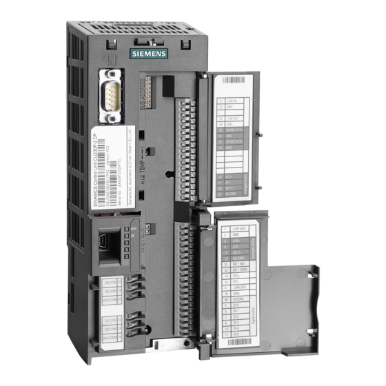
Siemens CU230P-2 HVAC Parameter Manual
Sinamics g120 control units
Hide thumbs
Also See for CU230P-2 HVAC:
- Manual (732 pages) ,
- Original instructions manual (456 pages) ,
- Getting started (56 pages)
Table of Contents
Advertisement
Advertisement
Table of Contents


Need help?
Do you have a question about the CU230P-2 HVAC and is the answer not in the manual?
Questions and answers