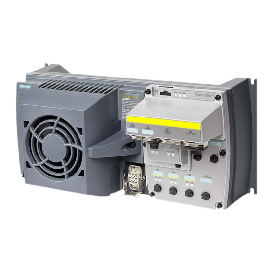
Siemens SINAMICS G120D Getting Started Manual
Power modules
Hide thumbs
Also See for SINAMICS G120D:
- List manual (910 pages) ,
- Operating instructions manual (398 pages) ,
- Original instructions manual (382 pages)


Need help?
Do you have a question about the SINAMICS G120D and is the answer not in the manual?
Questions and answers