Siemens SINAMICS G120 Operating Instructions Manual
Hide thumbs
Also See for SINAMICS G120:
- List manual (1256 pages) ,
- Manual (732 pages) ,
- Operating instructions manual (550 pages)

Related Manuals for Siemens SINAMICS G120


Summary of Contents for Siemens SINAMICS G120
- Page 1 Operating Instructions · Edition 11/2006 Control Unit CU240S CU240S DP CU240S DP-F Software version 2.1 SINAMICS G120 G120...
- Page 3 Introduction Safety notes Description SINAMICS Installing/Mounting SINAMICS G120 Control Units CU240S Commissioning (software) Operation Operating Instructions Service and maintenance Functions Technical data Spare parts/Accessories Appendix List of abbreviations Edition 11/2006, Software version V2.1 11/2006 A5E00766042B AA...
- Page 4 Trademarks All names identified by ® are registered trademarks of the Siemens AG. The remaining trademarks in this publication may be trademarks whose use by third parties for their own purposes could violate the rights of the owner.
-
Page 5: Table Of Contents
Table of contents Introduction............................. 1-1 Documents for the SINAMICS G120 ..................1-1 Safety notes............................2-1 Description.............................. 3-1 CU240S............................3-1 Accessories for the SINAMICS G120 ..................3-2 Features and functions of the CU240 ..................3-3 Layout and Block diagram ......................3-5 Interfaces of the CU240S variants ................... - Page 6 Table of contents 5.7.4.1 Series commissioning with the OP ..................5-47 5.7.4.2 Series commissioning with STARTER..................5-49 5.7.4.3 Inserting and removing the MMC..................... 5-50 5.7.4.4 Series commissioning with MMC ..................... 5-52 5.7.5 Reset parameters to factory settings ..................5-59 Commissioning the Fail-safe Functions ................... 5-61 5.8.1 Parameters for fail-safe functions ....................
- Page 7 Parameter data channel (PKW) ....................8-28 8.7.5 Timeouts and other errors......................8-34 Fixed frequencies........................8-37 2-/3-wire control ........................8-41 8.9.1 Siemens standard control (P0727 = 0) ..................8-42 8.9.2 2-wire control (P0727 = 1) ....................... 8-44 8.9.3 3-wire control (P0727 = 2) ....................... 8-45 8.9.4 3-wire control (P0727 = 3) .......................
- Page 8 Table of contents 8.18.3 Safe Torque Off........................8-107 8.18.4 Safe Stop 1 ..........................8-110 8.18.5 Safely-Limited Speed ......................8-114 8.18.6 Safe Brake Control......................... 8-136 8.19 Closed-loop Vdc control ......................8-138 8.19.1 Vdc_max controller......................... 8-139 8.19.2 Kinetic buffering ........................8-141 8.20 Positioning ramp down......................
- Page 9 Table of contents List of abbreviations..........................B-1 Abbreviations ..........................B-1 Index..............................Index-1 Tables Table 3-1 Interfaces of the Control Units CU240S..................3-6 Table 3-2 Following interfaces are available, see also figure "Variants of Control Units CU240S"..3-10 Table 3-3 Control terminals........................3-10 Table 3-4 Settings of the General I/O DIP switches ................
- Page 10 Table of contents Table 5-17 Automatic download fault codes ....................5-58 Table 5-18 Parameters for fail-safe functions .................... 5-65 Table 5-19 Example address for the PROFIBUS DP interface..............5-78 Table 5-20 PROFIBUS DP address ......................5-78 Table 5-21 PROFIBUS DP parameters...................... 5-79 Table 5-22 Parameters for flexible interconnection of process data............
- Page 11 Table of contents Table 7-5 Parameter accessing error numbers ..................7-12 Table 8-1 Parameter P0700........................8-1 Table 8-2 Parameter P1000........................8-2 Table 8-3 Binectors ............................ 8-3 Table 8-4 Connectors..........................8-5 Table 8-5 Possible settings of the digital inputs and analog inputs used as digital inputs ...... 8-14 Table 8-6 Parameters P0731 to P0733 (frequently used functions/states) ..........
- Page 12 Table A-8 "Safe Torque Off" function (STO).....................A-11 Table A-9 "Safe Stop 1" function (SS1) ....................A-12 Table A-10 "Safely-Limited Speed" function (SLS) ..................A-13 Table B-1 Abbreviations used with the SINAMICS G120 Products ............B-1 Control Units CU240S Operating Instructions, 11/2006, A5E00766042B AA...
-
Page 13: Introduction
Introduction Documents for the SINAMICS G120 Available documentation The following document types are available for the SINAMICS G120 inverters: ● Brochure ● Catalog ● Getting started Guide ● Operating Instructions ● Hardware Installation Manual ● Compact Operating Instructions (for the Control Units) ●... - Page 14 Introduction 1.1 Documents for the SINAMICS G120 Description of the documents Brochure The brochure is advertising literature designed to introduce the product to the marketplace. It contains a basic outline of the product with a brief overview of the technical capabilities of the product.
-
Page 15: Safety Notes
Please read the information carefully, since it is provided for your personal safety and will also help prolong the service life of your SINAMICS G120 product and the equipment to which it is connected. Control Units CU240S... - Page 16 Safety notes General Warning This equipment contains dangerous voltages and controls potentially dangerous rotating mechanical parts. Non-compliance with the Warnings or failure to follow the instructions contained in this manual can result in loss of life, severe personal injury or serious damage to property.
- Page 17 Safety notes Transport and storage Warning Correct transport, storage as well as careful operation and maintenance are essential for the proper and safe operation of the equipment. Caution Protect the equipment against physical shocks and vibration during transport and storage. It is important that the equipment is protected from water (rainfall) and excessive temperatures.
- Page 18 (see EN 60204, section 9.2.5.4). Repair Warning Repairs on equipment may only be carried out by Siemens Service, by repair centers authorized by Siemens or by authorized personnel who are thoroughly acquainted with all the warnings and operating procedures contained in this manual.
- Page 19 Safety notes Dismantling and disposal Caution The packaging of the inverter is re-usable. Retain the packaging for future use. Easy-to-release screw and snap connectors allow you to break the unit down into its component parts. You can recycle these component parts, dispose of them in accordance with local requirements or return them to the manufacturer.
-
Page 21: Description
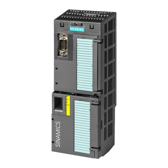
Description The SINAMICS G120 range The SINAMICS G120 inverter has been designed for the accurate and efficient control of the speed and torque for three-phase motors. The SINAMICS G120 system comprises two basic modules, the Control Unit (CU) and the Power Module (PM). -
Page 22: Accessories For The Sinamics G120
Description 3.2 Accessories for the SINAMICS G120 Accessories for the SINAMICS G120 Overview The following options are available for the SINAMICS G120 Inverters: Control Unit accessories ● OP (Operator Panel) ● PC connection kit ● MMC (Multi Media Card) ● CU Screen termination kit Power Module PM240 accessories ●... -
Page 23: Features And Functions Of The Cu240
Description 3.3 Features and functions of the CU240 Features and functions of the CU240 Common features ● Modular inverter ● Simple to install ● Signals can be interconnected using BICO technology ● Different data sets selectable ● Fast current limiting (FCL) for trip-free operation ●... - Page 24 Description 3.3 Features and functions of the CU240 Operating functions ● Adjustable setpoint channel ● Adjustable ramp-function generator (RFG) ● JOG mode ● Freely-assignable function blocks (FFB) ● Positioning ramp down ● Automatic restart (WEA) ● Flying restart ● Current limiting ●...
-
Page 25: Layout And Block Diagram
Description 3.4 Layout and Block diagram Layout and Block diagram Layout characteristics of the CU240S variants The figure below shows the various interfaces and control that are available on the Control Unit. Figure 3-1 Variants of Control Units CU240S Control Units CU240S Operating Instructions, 11/2006, A5E00766042B AA... - Page 26 Description 3.4 Layout and Block diagram Variants Table 3-1 Interfaces of the Control Units CU240S Control Unit CU240S CU240S DP CU240S DP-F Digital Inputs Fail-safe digital Inputs Digital Outputs Analog Inputs Analog Outputs PTC/KTY84 interface MMC interface Encoder interface 1, TTL or HTL 1, TTL or HTL 1, TTL or HTL Option port...
- Page 27 Description 3.4 Layout and Block diagram CU240S Block Diagram Figure 3-2 CU240S Block Diagram Control Units CU240S Operating Instructions, 11/2006, A5E00766042B AA...
- Page 28 Description 3.4 Layout and Block diagram CU240S DP Block Diagram Figure 3-3 CU240S DP Block diagram Control Units CU240S Operating Instructions, 11/2006, A5E00766042B AA...
- Page 29 Description 3.4 Layout and Block diagram CU240S DP-F Block Diagram Figure 3-4 CU240S DP-F Block diagram Control Units CU240S Operating Instructions, 11/2006, A5E00766042B AA...
-
Page 30: Interfaces Of The Cu240S Variants
Description 3.5 Interfaces of the CU240S variants Interfaces of the CU240S variants Overview Table 3-2 Following interfaces are available, see also figure "Variants of Control Units CU240S" CU240S CU240S DP CU240S DP-F MMC slot Option port Terminals General I/O DIP switches PROFIBUS DP DIP switches Status LEDs Power module interface (PM-IF) - Page 31 Description 3.5 Interfaces of the CU240S variants Terminal Designation Function CU240S/ CU240S DP-F CU240S DP U24V OUT Isolated output +24 V – max. 100 mA AI1+ Analog input 1 positive AI1- Analog input 1 negative AO0+ Analog output 0 positive (0/4 mA …...
- Page 32 Description 3.5 Interfaces of the CU240S variants Terminal Designation Function CU240S/ CU240S DP-F CU240S DP ENC BP Channel B non-inverting input ENC BN Channel B inverting input ENC ZP Channel 0 (zero) non-inverting input ENC ZN Channel 0 (zero) inverting input The control terminals have a maximum tighten torque of 0.25 Nm (2.2 lbf.in) and a nominal cross section of 1.5 mm (AWG 14) for cable.
-
Page 33: Table 3-4 Settings Of The General I/O Dip Switches
Description 3.5 Interfaces of the CU240S variants Figure 3-6 CU240S DP-F Control Terminals General I/O DIP switches (CU240S, CU240S DP and CU240S DP-F) There are seven general I/O DIP switches that allow the settings described below. In the factory setting the I/O DIP switches are in the OFF position. Figure 3-7 General I/O DIP switches Table 3-4... -
Page 34: Table 3-5 Example Address For The Profibus Dp Interface
Example 2: Address = 88 = 8 + 16 + 64 Status display via LEDs The SINAMICS G120 inverters provide multiple functions and operating states which are indicated via LEDs. LEDs for standard CUs The status for standard inverters is displayed via the following LEDs:... - Page 35 Description 3.5 Interfaces of the CU240S variants LEDs for CUs with fail-safe functions For inverters with fail-safe functions the following additional LEDs are available: Figure 3-10 LEDs for CUs with fail-safe functions For detailed description refer to "LED overview" in section "Service and maintenance". Power module interface All necessary control signals for the correct operation of the inverter-system are transferred between the CU and PM utilizing the Power module interface (PM-IF).
-
Page 36: Factory Settings Of The Cu240S Control Units
Description 3.6 Factory settings of the CU240S control units Factory settings of the CU240S control units Factory Settings for command and setpoint source P0700 = 0 is the same as P0700 = 2 or 6 dependend on type of Control Unit. Note Setting P0700 = 6 (command source via fieldbus communication) and P1000 = 6 (setpoint source via fieldbus communication) are not possible with a CU240S... - Page 37 Description 3.6 Factory settings of the CU240S control units Table 3-7 BICO Command Parameter Parameter CU240S CU240S DP, CU240S DP-F P0700 = 2 P0700 = 6 P0840 722.0 2090.0 P0842 P0844 2090.1 P0845 19.1 19.1 P0848 2090.2 P0849 P0852 2090.3 Table 3-8 Command Sources for Fixed Frequencies Parameter...
-
Page 39: Installing/Mounting
Installing/Mounting Installing the Control Unit The CU controls the functions of the PM. The CU cannot be used without a PM, also the PM cannot be used without a CU. Warning An inverter can be switched on unintentionally if the installation is not performed correctly. The inverter must be started-up by personnel who are qualified and trained in installing systems of this type. -
Page 40: Fitting The Cu To The Pm
Installing/Mounting 4.1 Fitting the CU to the PM Fitting the CU to the PM Fitting the Control Unit to the Power Module The Control Unit is snapped on to the Power Module as shown in the figure below. To disconnect the CU push the release button on top of the PM. The process of fitting the Control Unit to the Power Module is the same technique independent from the type of G120 control unit or G120 power module. - Page 41 Installing/Mounting 4.1 Fitting the CU to the PM Caution Care must be taken to ensure that the 24 V DC power is connected correctly or damage to the Control Unit may occur. Max. cable length on 24 V DC supply and I/O cables connected to CU must not exceed 10 m.
-
Page 42: Connecting The Control Unit Via Terminals
Installing/Mounting 4.2 Connecting the Control Unit via terminals Connecting the Control Unit via terminals General To have access to the control terminals, the terminal cover must be removed, as shown in the figure below. The control terminals have a maximum tighting torque of 0.25 Nm (2.2 lbf.in) and a nominal cable cross section of 1.5 mm Figure 4-3 Removing the Control Unit terminal cover... -
Page 43: Connecting A Cu240S Via Terminals
To control the CU240S DP or CU240S DP-F via terminals is also possible, but in this case the parameter settings for command and setpoint source have to be changed. In this section examples of controlling a SINAMICS G120 inverter with a CU240S via terminals are shown. - Page 44 Installing/Mounting 4.2 Connecting the Control Unit via terminals Figure 4-5 Default control wiring of a CU240S Frequency setpoint and an additional setpoint via terminals AI0 and AI1 used as voltage inputs This type of control wiring allows a main frequency setpoint and an additional setpoint to be established, using potentiometers on analog inputs AI0 and AI1.
- Page 45 Installing/Mounting 4.2 Connecting the Control Unit via terminals DIP switch Settings The general I/O DIP switches 1 and 2 are used to configure the analog inputs (AI). For using AI0 and AI1 as voltage inputs set DIP switches 1 and 2 to OFF position.For detailed information refer to "Analog input"...
- Page 46 Installing/Mounting 4.2 Connecting the Control Unit via terminals Frequency setpoint and an additional setpoint via terminals AI0 and AI1 used as current inputs This type of control wiring allows a main frequency setpoint and an additional setpoint to be established, for example from a PLC. The figure below shows the wiring that is necessary to accomplish this functionality.
- Page 47 Installing/Mounting 4.2 Connecting the Control Unit via terminals Figure 4-7 Terminal connection for using AI0 and AI1 as current inputs for main and additional setpoint Control Units CU240S Operating Instructions, 11/2006, A5E00766042B AA...
-
Page 48: Connecting A Cu240S Dp Or Cu240S Dp-F Via Profibus Dp
Connecting a CU240S DP or CU240S DP-F via PROFIBUS DP PROFIBUS DP Interface The function of the PROFIBUS DP interface is to provide a PROFIBUS DP-based link between inverters of the SINAMICS G120 product range and higher-level automation systems e.g. SIMATIC S7. Configuration with SIMATIC S7 The layout of the PROFIBUS DP interface and the DIP switches for setting the PROFIBUS DP address are shown in the Commissioning section. -
Page 49: Connecting The Profibus Dp
Installing/Mounting 4.3 Connecting a CU240S DP or CU240S DP-F via PROFIBUS DP Setting the PROFIBUS DP address via DIP switches The PROFIBUS DP address can be set via DIP switch, as shown in the table below. Table 4-1 Example address for the PROFIBUS DP interface DIP switch Add to address Example 1: Address = 3 = 1 + 2... -
Page 50: Table 4-3 Permissible Cable Length For One Segment
The maximum cable lengths are dependent on the baud rate (transmission speed). The maximum cable lengths specified in the table below can be guaranteed only with PROFIBUS bus cables (for example, Siemens PROFIBUS bus cable, order number 6XV1830-0EH10). Table 4-3... - Page 51 8 ± 0.5 mm diameter Note We recommend only these two connectors since they can be used without difficulty for all SINAMICS G120 models and are completely compatible in terms of outgoing cable unit angle. Control Units CU240S 4-13 Operating Instructions, 11/2006, A5E00766042B AA...
- Page 52 Installing/Mounting 4.3 Connecting a CU240S DP or CU240S DP-F via PROFIBUS DP Bus terminator Each bus segment must have a resistor network, i.e. a bus terminator, at both ends. Where the recommended bus connectors have been used, the bus terminator can be switched in and out by means of switches as shown in the figure below.
-
Page 53: Screening The Bus Cable And Emc Precautions
Installing/Mounting 4.3 Connecting a CU240S DP or CU240S DP-F via PROFIBUS DP Removing a bus connector You can remove the bus connector with looped-through bus cable from the PROFIBUS DP interface at any time without interrupting the data exchange on the bus. Only the final node must be terminated. - Page 54 Installing/Mounting 4.3 Connecting a CU240S DP or CU240S DP-F via PROFIBUS DP Equipotential bonding Differences in potential (for example, due to different mains supplies) between the inverters and the PROFIBUS DP master must be avoided. ● Recommended equipotential bonding cables: –...
-
Page 55: Connecting A Cu240S Via Uss
Installing/Mounting 4.4 Connecting a CU240S via USS Connecting a CU240S via USS RS485 Interface The built-in connector is a 9-way SUB-D female connector for RS485. Table 4-5 9-way SUB-D connector for RS485 Signal (drive side) Comment Screen Potential equilisation Unused RS485P Receive- and transmit signal (+) Unused... -
Page 57: Commissioning (Software)
Commissioning (software) General commissioning information General commissioning information The inverter can be adapted to various applications by changing the parameter values. The parameter values can be changed, using one of the following optional components: ● The OP (Operator Panel), plugged into the Option port of the Control Unit ●... -
Page 58: Parameters
Commissioning (software) 5.2 Parameters Parameters Overview of parameters The inverter is adapted to a particular application using the appropriate parameters. This means that each parameter is identified by a parameter number and specific attributes (e.g. readable, can be written into BICO attribute, group attribute etc.). Within any one particular inverter system, the parameter number is unique. -
Page 59: Write Parameters
Commissioning (software) 5.2 Parameters 5.2.1 Write parameters Description Parameters which can be written into and displayed are indicated by the prefix "P". These parameters directly influence the behavior of a function. The value of this parameter is saved in non-volatile memory (EEPROM) as long as the appropriate option was selected (non-volatile data save). -
Page 60: Parameter Attributes
Commissioning (software) 5.2 Parameters 5.2.3 Parameter Attributes Overview In the Parameter List, the header line of each parameter shows all the attributes and groups for that specific parameter. The figure below shows the details for parameter P0700 and r1515. Figure 5-2 Description of attributes for parameter P0700 Figure 5-3 Description of attributes for parameter r1515... -
Page 61: Table 5-1 Parameter Attributes - Bico
P0003. On the other hand, for STARTER, only access levels 0 and 3 are relevant. For example, parameters with access level 3 cannot be changed if the appropriate access level has not been set. The following access levels are implemented in the SINAMICS G120 inverter units: Table 5-2 Parameter attributes - access level... -
Page 62: Table 5-3 Parameter Attributes - Change State
The data type of a parameter defines the maximum possible value range. Five data types are used for SINAMICS G120. They either represent an unsigned integer value (U16, U32) or a floating-point value (float). The value range is frequently restricted by a minimum and maximum value (min, max) or using inverter/motor quantities. - Page 63 5.2 Parameters Unit For SINAMICS G120, the units of a particular parameter involve the physical quantity (e.g. m, s, A). Quantities are measurable properties/characteristics of physical objects, operations, states and are represented using characters of a formula (e.g. V = 9 V).
- Page 64 Commissioning (software) 5.2 Parameters Grouping The parameters are sub-divided into groups according to their functionality. This increases the transparency and allows a quicker and more efficient search for specific parameters. Furthermore, parameter P0004 can be used to control the specific group of parameters that are displayed on the OP.
-
Page 65: Table 5-8 Parameter Attributes - Quick Commissioning
Commissioning (software) 5.2 Parameters Note Parameter values that are changed using STARTER or a higher-level control do not have to be acknowledged. Quick commissioning This parameter attribute identifies as to whether the parameter is included in the quick commissioning (QC) (P0010 = 1). Table 5-8 Parameter attributes - Quick commissioning Description... -
Page 66: Factory Settings
Rated motor power P0307 Rated motor frequency P0310 Rated motor speed P0311 (A Siemens standard motor is recommended.) Further, the following conditions must be fulfilled: Control (ON/OFF command) using digital inputs (CU240S) See pre-assigned inputs below. Asyncronous motor P0300 = 1... -
Page 67: Table 5-11 Pre-Assignment Of The Digital Inputs For A Cu240S *)
Commissioning (software) 5.3 Factory settings Table 5-11 Pre-assignment of the digital inputs for a CU240S *) Digital Inputs Terminals Parameter Function Active Command source* P0700 = 2 Terminals Digital Input 0, DI0 P0701 = 1 ON/OFF1 Digital Input 1, DI1 P0702 = 12 Reversing Digital Input 2, DI2... -
Page 68: Parameterization With Operator Panel
Commissioning (software) 5.4 Parameterization with Operator Panel Parameterization with Operator Panel The Operator Panel (OP) The OP is available as an option to enhance the effectiveness of parameterizing and control of the inverter. The control signals and speed reference can easily be set by pressing the appropriate buttons. -
Page 69: Function Keys Of The Op
Commissioning (software) 5.4 Parameterization with Operator Panel 5.4.1 Function Keys of the OP Operator Panel - function keys Table 5-12 OP keys and their functions Operator Panel Function Effects Status The LCD indicates the settings which the drive inverter is presently using. display Start motor The inverter is started by pressing the key. -
Page 70: Changing Parameters Via Op
Commissioning (software) 5.4 Parameterization with Operator Panel 5.4.2 Changing parameters via OP Changing parameter with the OP The description below serves as an example that shows how to change any parameter using the OP. Table 5-13 Changing P0003 - parameter access level Step Result on display Press... -
Page 71: Parameterization With Mmc
Commissioning (software) 5.5 Parameterization with MMC Parameterization with MMC Overview A G120 inverter can be parameterized by downloading a parameter set from the MMC to the inverter. The download can be performed as ● manual download ● automatic download ● start-up download A detailed download description can be found in the operation section. -
Page 72: Parameterization With Starter
Commissioning (software) 5.6 Parameterization with STARTER Parameterization with STARTER Commissioning with STARTER The following interfaces - which are Control Unit dependent available: Table 5-15 Connection possibilities for STARTER Type USS on RS232 USS on RS485 PROFIBUS DP PC connected to CU PC Connection Kit Sub D cable &... - Page 73 Commissioning (software) 5.6 Parameterization with STARTER Note Via P0014 the store mode can be changed, • P0014 = 0: parameter changes stored in RAM (default) • P0014 = 1: parameter changes stored in EEPROM Parameter sets that have been changed offline can be transferred to the inverter using the download button.
-
Page 74: Commissioning Modes
Commissioning (software) 5.7 Commissioning modes Commissioning modes Commissioning overview Before commissioning is started, the following data must must be available: ● Line supply frequency ● Motor rating plate data ● Command/setpoint sources ● Min./max. frequency or ramp-up/ramp-down time ● Control mode An example for a rating plate is shown in the figure below. - Page 75 Commissioning (software) 5.7 Commissioning modes Note Commissioning the inverter with STARTER can be performed via "Configure drive unit". "Commissioning the application" should only be performed if the inverter–motor combination provides a satisfactory result. Common commissioning information If the inverter is to be commissioned from a defined state, it can be reset to its default settings by performig a factory reset (see section "Reset parameters to factory settings") The following check list should help you to commission the Inverter without any problems and to guarantee a high degree of availability:...
- Page 76 Commissioning (software) 5.7 Commissioning modes Notice Behavior of inverter on completion of commissioning The following behavior should be taken into account when commissioning the inverter: • standard commissioning with P0014 = 0: Parameters are only stored in RAM. RAM -> EEPROM can be started: –...
-
Page 77: Table 5-16 Quick Commissioning
Commissioning (software) 5.7 Commissioning modes Performing Quick Commissioning via OP For applications using V/f (P1300 = 0 [default]) or Flux Current Control (FCC) (P1300 = 1 or 6), quick commissioning can be accomplished by setting the following parameters: Enter the line frequency P0100 Enter the rating label data P0304, P0304, P0305, P0307, P0310 and P0311... - Page 78 Commissioning (software) 5.7 Commissioning modes Parameter Description (Parameter name and factory setting (if not variable) in bold) Setting P0234 = ? Filter capacity Capacity of the used output filter (phase value, if connected in triangle 3*C Δ can only be set, if an external output filter is selected (P230 = 4) P0300 = 1 Select motor type 1: Asynchronous rotational motor...
- Page 79 5: USS on RS485 6: Fieldbus (Default for CU240S DP and CU240S DP-F) P0727 = 0 Selection of 2-/3-wire method Determines the control method using the terminals. 0: Siemens (start/dir) 1: 2-wire(fwd/rev) 2: 3-wire(fwd/rev) 3: 3-wire(start/dir) P1000 = 2 Selection of frequency setpoint*...
- Page 80 Commissioning (software) 5.7 Commissioning modes Parameter Description (Parameter name and factory setting (if not variable) in bold) Setting P1121 = ? Ramp-down time Enter the time (in seconds) in which the motor should decelerate (using braking) from the maximum frequency P1082 down to standstill. If the ramp-down time is set too short, this can cause alarm A0501 (current limit value) or A0502 (overvoltage limit value) or tripping the inverter with fault F0001 (overcurrent) or F0002 (overvoltage).
- Page 81 Commissioning (software) 5.7 Commissioning modes Next to "Quick Commissioning" Next to "Quick Commissioning" the "Motor Data Identification" and additionally in case of vector mode (P1300 = 20/21) the "Speed Control Optimisation" should be performed. Both need an ON command to start. Motor data identification Warning The motor data identification routine MUST not be used for loads which are potentially...
-
Page 82: Motor Data Identification
Commissioning (software) 5.7 Commissioning modes Speed control optimisation Parameter Description (Parameter name and factory setting (if not variable) in bold) P0010 = 0 Commissioning parameter filter* Check if P0010 = 0 (Ready) P1960 = 1 Speed control optimisation 0: Disable 1: Enable Start Speed control optimisation command... - Page 83 Commissioning (software) 5.7 Commissioning modes Figure 5-7 Equivalent circuit diagram (ECD) In addition to the ECD data, the motor magnetizing characteristic (see the figure above) can be determined using the motor data identification (P1910 = 3). If the motor combination is operated in the field-weakening range (which is above the nominal frequency of the motor), then this characteristic should be determined, especially when Vector control is being used.
- Page 84 Commissioning (software) 5.7 Commissioning modes temperature P0625. Only then is the correct temperature adaptation of the resistances possible during operation. The motor data identification routine operates with the results of the "Complete parameterization" P0340 = 1 or the motor equivalent diagram data which was last saved. The results become increasingly better the more times that the identification routine is executed (up to 3 times).
-
Page 85: Calculating The Motor And Control Data
Commissioning (software) 5.7 Commissioning modes If Problems occur during the identification run, for example, the current controller oscillates, then the rating plate data should be re-checked and an approximately correct magnetizing current P0320 entered. The motor data identification routine should then be re-started by called P0340 = 1. - Page 86 Commissioning (software) 5.7 Commissioning modes Performing the calculation of motor and control data via OP Parameter Description (Parameter name and factory setting (if not variable) in bold) Setting P0340 = 1 Calculation of motor parameters This parameter is required during commissioning in order to optimize the operating behavior of the inverter.
-
Page 87: Commissioning The Application
Commissioning (software) 5.7 Commissioning modes 5.7.3 Commissioning the application Commissioning the application After the motor - Inverter combination has been commissioned using quick commissioning, the following parameters should be adapted and set according to the requirements of your specific application. As an example, the following points should be considered: ●... - Page 88 Commissioning (software) 5.7 Commissioning modes General settings Parameter Description (Parameter name and factory setting (if not variable) in bold) Setting P0003 = 3 User access level* 1: Standard: Allows access into most frequently used parameters. 2: Extended: Allows extended access e.g. to inverter I/O functions 3: Expert: For expert use only P0210 = ? Supply voltage (enter the voltage in V)
- Page 89 Commissioning (software) 5.7 Commissioning modes Temperature Sensor Parameter Description (Parameter name and factory setting (if not variable) in bold) Setting P0601 = 0 Motor temperature sensor 0: No sensor (→ P0610) P0601 = ? 1: PTC thermistor (→ P0604) 2: KTY84 (→ P0604) P0604 = ? Threshold motor temperature Enter the warning threshold for motor overtemperature protection.
- Page 90 Commissioning (software) 5.7 Commissioning modes Selection of command source The available command sources depend on the used CU. Default setting on the control unit used the command source is set per default to different values. Parameter Description (Parameter name and factory setting (if not variable) in bold) Setting P0700 = 2/6 Selection of command source...
- Page 91 Commissioning (software) 5.7 Commissioning modes Assigning digital input functions Parameter Description (Parameter name and factory setting (if not variable) in bold) Setting P0701 = 1 Terminal 5: factory settings for Possible values for P0701 to P0709: Digital Input 0 (DI0) CU240S 0: Digital input disabled 1: ON/OFF1...
- Page 92 Commissioning (software) 5.7 Commissioning modes Assigning digital output functions Parameter Description (Parameter name and factory setting (if not variable) in bold) Setting P0731 = 52:3 BI: function of digital output 0 (DO0), defines the source for digital output 0 Terminal 18: DO0, NC/Terminal 19: DO0, NO/Terminal 20: DO0, COM 52:3 Inverter fault active P0732 = 52:7 BI: function of digital output 1,defines the source for digital output 1...
- Page 93 Commissioning (software) 5.7 Commissioning modes Frequency setpoint via analog input (AI) (P1000 = 2) Parameter Description (Parameter name and factory setting (if not variable) in bold) Setting P0756 = 0 AI type Defines the type of the analog input and also enables analog input monitoring. 0: Unipolar voltage input (0 to +10 V) 1: Unipolar voltage input with monitoring (0 V …...
- Page 94 Commissioning (software) 5.7 Commissioning modes Frequency setpoint via fixed frequency (P1000 = 3) Parameter Description (Parameter name and factory setting (if not variable) in bold) Setting P1016 = 1 Fixed frequency mode, defines The fixed frequency can be selected via four digital the selection method for fixed inputs (default DI3 …...
- Page 95 Commissioning (software) 5.7 Commissioning modes Analog outputs Parameter Description (Parameter name and factory setting (if not variable) in bold) Setting P0771 = 21 CI: Analog output Defines the function of the 0 mA … 20 mA analog output 21: CO: actual frequency (scaled according to P2000) 24: CO: actual output frequency (scaled according to P2000) 25: CO: actual output voltage (scaled according to P2001) 26: CO: actual DC-link voltage (scaled according to P2001)
- Page 96 Commissioning (software) 5.7 Commissioning modes JOG frequency Parameter Description (Parameter name and factory setting (if not variable) in bold) Setting P1057 = 1 JOG Enable P1057 = 0 JOG-function diabled P1057 = 1 JOG-function enabled P1058 = 5 JOG frequency right Frequency in Hz when the motor is being jogged in the clockwise direction of roatation.
- Page 97 Commissioning (software) 5.7 Commissioning modes Skip Frequency Parameter Description (Parameter name and factory setting (if not variable) in bold) Setting P1091 = 7.5 Skip frequency 1 (entered in Hz) Avoids mechanical resonance effects and suppresses (skips) frequencies in the range around the skip frequency ± P1101 (skip frequency bandwidth).
- Page 98 Commissioning (software) 5.7 Commissioning modes Parameters to set before finishing the application setting The following parameters should be configured for each application. Parameter Description (Parameter name and factory setting (if not variable) in bold) Setting P1800 = 4 Pulse frequency (kHz) The pulse frequency can be changed in 2 kHz steps.
-
Page 99: Series Commissioning
Commissioning (software) 5.7 Commissioning modes Finishing the application setting Parameter Description (Parameter name and factory setting (if not variable) in bold) Setting P0971 = 1 Transfer data from RAM to EEPROM 0: Disabled 1: Start data transfer, RAM → EEPROM All of the parameter changes are transferred from the RAM into the EEPROM which means that they are saved in a non-volatile state within the Inverter (data is not lost when the power fails). - Page 100 Commissioning (software) 5.7 Commissioning modes Caution Parameter download between different types of control units and of different firmware versions is not recommended. It is possible to download parameter sets from different CU types, however, as the parameter sets might differ, the user is fully responsible for the consistency of the downloaded parameter set.
- Page 101 Commissioning (software) 5.7 Commissioning modes Warning For series commissioning, all of the communication interfaces as well as also the digital and analog interfaces are re-initialized. This results in a brief communications failure or causes the digital outputs to switch. Potentially hazardous loads must be carefully secured before starting a series commissioning.
- Page 102 Commissioning (software) 5.7 Commissioning modes Note Restrictions to be considered when performing upload and download: • Only the parameter set stored in the EEPROM of the inverter is uploaded. • Fail-safe parameters cannot be uploaded via OP or STARTER. • Once the upload or download procedure has started, it should not be interrupted. •...
-
Page 103: Series Commissioning With The Op
Commissioning (software) 5.7 Commissioning modes 5.7.4.1 Series commissioning with the OP Upload and download a parameter set with an OP With an OP a single parameter set can be uploaded from an inverter and then downloaded into another inverter. To copy a parameter set from one inverter to another, the following procedure should be performed. - Page 104 Commissioning (software) 5.7 Commissioning modes Download a parameter set with an OP Prerequisites ● Supply voltage is active for the download inverter ● The download inverter is in "Ready State". Parameter Description (Parameter name and factory setting (if not variable) in bold) Setting Fit the OP to the inverter and perform the download according the flow chart.
-
Page 105: Series Commissioning With Starter
Commissioning (software) 5.7 Commissioning modes 5.7.4.2 Series commissioning with STARTER Upload a parameter set with STARTER Prerequisites ● An inverter with an apropriate parameter set is available (upload inverter) ● STARTER is installed on the PC used for series commissioning ●... -
Page 106: Inserting And Removing The Mmc
Commissioning (software) 5.7 Commissioning modes 5.7.4.3 Inserting and removing the MMC Inserting the MMC To insert an MMC into the Control Unit of the inverter, the process shown in the figure below should be performed. Figure 5-10 Installing the MultiMedia Card (MMC) Warning When inserting an MMC during operation Alarm A0564 appears if P8458 is set to 0. - Page 107 Commissioning (software) 5.7 Commissioning modes Removing the MMC To remove the MMC from the Control Unit, the following procedure should be performed: 1. Using a thin-bladed screwdriver, push down the release-catch on the MMC housing. 2. Grasp the MMC gently and pull upwards. This procedure is shown in the figure below.
-
Page 108: Series Commissioning With Mmc
Commissioning (software) 5.7 Commissioning modes 5.7.4.4 Series commissioning with MMC Upload and download a parameter set with an MMC A parameter set can be uploaded from an inverter and then downloaded into another inverter. The following important restrictions must be considered when using the copying procedure: ●... - Page 109 Commissioning (software) 5.7 Commissioning modes Upload a parameter set with an MMC Prerequisites To perform a series commissioning with the MMC the following conditions must be fullfiled: ● Supply voltage is active for the upload inverter ● The upload inverter is in "Ready State". Note Before uploading, the parameters will be copied from RAM to EEPROM Parameter...
- Page 110 Commissioning (software) 5.7 Commissioning modes Manual Download of a parameter set with an MMC Note The following important restrictions should be considered when using the download procedure: • During the download the inverter will not react to any commands. • Once the download procedure has started, it cannot be interrupted. •...
- Page 111 Commissioning (software) 5.7 Commissioning modes Automatic Download The automatic download at start-up is controlled via P8458. With the automatic download all necessary parameters including the parameters regarding fail-safe functions are downloaded into the inverter. Note MMC for "automatic download" For an automatic download always the file clone00.bin will be used. The user has to take care, that clone00.bin (saved as "clone00.bin"...
- Page 112 Commissioning (software) 5.7 Commissioning modes Power ON go to swap? Swap behavior MMC plugged? P8458 > 0? (Clone Control) valid Par. set?/Safety settings compliant? P8458 = 1? (Clone Control) P7844 = 1? P8458 = 0 (acceptance test/ (Clone Control) confirmation) Power Stack type compliant? adjust CU parameters...
- Page 113 Commissioning (software) 5.7 Commissioning modes The possible settings for P8458 and their functions are given below. P8458 = 0: Automatic parameter download from the MMC is inhibited. P8458 = 1: Automatic parameter download from the MMC only once (at the next start-up of the CU (default setting)).
- Page 114 Commissioning (software) 5.7 Commissioning modes Automatic download fault If the automatic download process fails, the CU will return to the parameter set previously held in the EEPROM and the following fault codes are generated: Table 5-17 Automatic download fault codes Fault code Description F0061...
-
Page 115: Reset Parameters To Factory Settings
Commissioning (software) 5.7 Commissioning modes 5.7.5 Reset parameters to factory settings Overview With a factory setting a defined initial state of all of the inverter parameters can be realized. You can re-establish the initial state by carrying-out a factory via p0970. The factory setting values are designated as "Factory setting"... - Page 116 Commissioning (software) 5.7 Commissioning modes Warning Fail-safe parameters When using Standard CUs, only the factory reset with P0970 = 1 must be taken into account. When using CUs with fail-safe functions two reset methods are available: • P0970 = 1 resets only non fail-safe function relating parameters (application parameters).
-
Page 117: Commissioning The Fail-Safe Functions
Commissioning (software) 5.8 Commissioning the Fail-safe Functions Commissioning the Fail-safe Functions Available fail-safe functions ● Safe Torque Off (STO) ● Safe Stop 1 (SS1) ● Safely Limited Speed (SLS) ● Safe Brake Control (SBC). The signals for STO, SS1 and SLS are connected to the Control Unit, an EM-Brake is connected to the Power Module. - Page 118 Commissioning (software) 5.8 Commissioning the Fail-safe Functions Behavior of PROFIBUS and PROFIsafe address The behavior of PROFIBUS address (P0918) and PROFIsafe address (P9810) is shown in the following tables: Case DIP switch P0918 P9810 Behavior setting value value PROFIBUS and PROFIsafe address identical and Not allowed determined by P0918.
- Page 119 Commissioning (software) 5.8 Commissioning the Fail-safe Functions Commissioning parameters regarding fail-safe functions Parameters regarding fail-safe functions can only be accessed on a Control Unit with fail- safe functions, on a Standard CU this parameters are not available. For safety reason parameters are handled by pairs and stored on two separate processors within the CU with fail-safe functions.
-
Page 120: Parameters For Fail-Safe Functions
Commissioning (software) 5.8 Commissioning the Fail-safe Functions To select the PROFIsafe communications, following actions would be performed: 1. P9603 would be set to the value 128. 2. The system would read the change, process the information to the drive processor memory and verify that the information has been received correctly. -
Page 121: Table 5-18 Parameters For Fail-Safe Functions
Commissioning (software) 5.8 Commissioning the Fail-safe Functions Table 5-18 Parameters for fail-safe functions Parameter Description Unit Default Min. Max. value value value Drive processor P9601 SI enable parameter P9602 SI enable safe brake monitoring P9603 SI Selection of Safety Source P9650 SI Safe Digital Input debounce delay time 2000... -
Page 122: Password For Fail-Safe Functions
Commissioning (software) 5.8 Commissioning the Fail-safe Functions 5.8.2 Password for fail-safe functions Password for fail-safe functions There are four parameters associated with the password protection system. All these parameters require level 3 access (only important when using OP) – the parameters are as follows: ●... -
Page 123: General Steps For Commissioning Fail-Safe Functions
Commissioning (software) 5.8 Commissioning the Fail-safe Functions 5.8.4 General steps for commissioning fail-safe functions General steps to change fail-safe funcitons The parameters designated with an "*" offer more setting possibilities than are listed here. Refer to the parameter list for additional setting possibilities. The following steps must always be carried-out when changing fail-safe functions: Parameter Description... -
Page 124: Common Step-By-Step Descriptions For Fail-Safe Functions
Commissioning (software) 5.8 Commissioning the Fail-safe Functions 5.8.5 Common step-by-step descriptions for fail-safe functions Change password Parameter Description Unit Default Min. Max. P9761 SI input password 1000 99999 The safety password is entered in this parameter to get access to change the fail-safe parameters. - Page 125 Commissioning (software) 5.8 Commissioning the Fail-safe Functions Select fail-safe command source Parameter Description Unit Default Min. Max. P9603 = ? SI Selection of Safety Source Fail-safe parameter for selection of the fail-safe input signals. The fail- safe input signals can be taken either from PROFIsafe or from the digital inputs of G120.
- Page 126 Commissioning (software) 5.8 Commissioning the Fail-safe Functions Filter time of fail-safe digital inputs Parameter Description Unit Default Min. Max. P9651 = ? Safe input filter delay time 1000 Defines the response time delay of the safe digital inputs. Signals that are shorter than the specified time are not processed as fail-safe signals but ignored.
- Page 127 Commissioning (software) 5.8 Commissioning the Fail-safe Functions Test stop interval setting Parameter Description Unit Default Min. Max. P9659 = ? SI maximum time until test stop* 8760.0 The time interval between test stops is specified. The remaining time until a test stop is required is shown in r9660. When r9660 reaches zero, the time interval has expired and warning A1699 is activated.
- Page 128 Commissioning (software) 5.8 Commissioning the Fail-safe Functions Safe Stop 1 setting Parameter Description Unit Default Min. Max. P9680 = ? SI braking ramp delay 99000 Time [in ms] between selecting the safe braking ramp (SBR) and the activation of the monitoring ramp. The actual frequency is compared to the frequency of the monitoring ramp when the SBR is active.
- Page 129 Commissioning (software) 5.8 Commissioning the Fail-safe Functions Safely-limited Speed Parameter Description Unit Default Min. Max. P9690 SI setpoint for SLS 10.0 300.0 Speed setpoint that is used when the safely limited speed (SLS) is selected. Depending on the setting in P9692/P9892 the frequency of P9690/P9890 may also serve as a speed threshold instead of a setpoint (see P9692).
-
Page 130: Safety Factory Reset
Commissioning (software) 5.8 Commissioning the Fail-safe Functions 5.8.6 Safety factory reset Safety factory reset The safety factory reset sets all fail-safe parameters to its default value except the following: ● P9760 SI internal password ● P9761 SI input password ● P9762 SI change password ●... -
Page 131: Acceptance Test And Acceptance Log
Commissioning (software) 5.8 Commissioning the Fail-safe Functions 5.8.7 Acceptance Test and Acceptance Log Description In order to verify the parameters for the fail-safe functions, an acceptance test must be carried-out after commissioning, reset and also when changing a completely backed-up data set of the parameters for the fail-safe functions (e.g. - Page 132 Commissioning (software) 5.8 Commissioning the Fail-safe Functions Contents of a complete acceptance test Documentation Documentation of the machine including the fail-safe functions. ● Machine description and overview/block diagram ● Fail-safe functions for each drive ● Description of the fail-safe devices/equipment. Function test Checking the individual fail-safe functions that are used.
-
Page 133: Commissioning With Profibus Dp
PROFIdrive Profile User data structure defined in PROFIdrive Profile 4.0 The SINAMICS G120 range of inverters can be controlled through the cyclical PROFIBUS DP channel. The structure of user data for the cyclical/acyclical channel is defined in the PROFIdrive Profile, version 4.0. - Page 134 Commissioning (software) 5.9 Commissioning with PROFIBUS DP Figure 5-13 PROFIBUS DP address DIP-switches The PROFIBUS DP address can be set between 1 and 125, as shown in the table below. Table 5-19 Example address for the PROFIBUS DP interface DIP switch Add to address Example 1: Address = 3 = 1 + 2 Example 2: Address = 88 = 8 + 16 + 64...
- Page 135 Commissioning (software) 5.9 Commissioning with PROFIBUS DP PROFIBUS DP parameters The following parameters must be set to start-up the PROFIBUS DP interface: Table 5-21 PROFIBUS DP parameters Parameter Content P0918 PROFIBUS address P0700 Fast selection command source P0922 Selects the PROFIBUS telegram standard P1000 Fast selection frequency setpoint P2038...
- Page 136 P2041.03 Select displayed diagnostics 0: Standard diagnostics screen. >0: Special diagnostics (for SIEMENS internal use only) Caution The watchdog function should not be deactivated! If the monitoring function is deactivated and the PROFIBUS DP interface fails, the inverter will not recognize a fault condition and continue to operate even if a fault condition exists.
- Page 137 Commissioning (software) 5.9 Commissioning with PROFIBUS DP Process data monitoring Two parameters determine how process data are monitored: ● watchdog function on the PROFIBUS DP interface (standard slave function according to PROFIBUS) The watchdog function on the PROFIBUS DP interface is normally activated. It can be deactivated by means of the PROFIBUS master configuring tool.
-
Page 138: Data Structures Within Profidrive Profile
Extended configuration for the SINAMICS G120 Up to 6 process data words (PZD), with a different number of setpoints and actual values if desired, can be configured on the SINAMICS G120. They are combined to standard and manufacturer-specific telegrams. Telegrams The selection of a telegram via P0922 determines on the drive unit side which process data is transferred between master and slave. -
Page 139: Standard Telegram Structure
Commissioning (software) 5.9 Commissioning with PROFIBUS DP Used telegram types The following telegrams can be set via parameter P0922: Standard telegrams The standard telegrams are structured in accordance with the PROFIdrive Profile. The internal process data links are set up automatically in accordance with the telegram number setting. -
Page 140: Vik/Namur Telegram Structure
Commissioning (software) 5.9 Commissioning with PROFIBUS DP Figure 5-14 Standard telegrams with different settings of P0922 5.9.5 VIK/NAMUR Telegram structure Description Figure 5-15 Telegram structure VIK/NAMUR Control Units CU240S 5-84 Operating Instructions, 11/2006, A5E00766042B AA... -
Page 141: Profisafe Telegram Structure
Commissioning (software) 5.9 Commissioning with PROFIBUS DP If VIK/NAMUR telegram is selected with P0922 = 20, the parameter P2038 "Selection of actual profile" will be set to VIK/NAMUR automatically. It is also necessary to set the ident number (GSD) via parameter P2042: ●... -
Page 142: Switch Over Behavior Of Communication Telegram
Commissioning (software) 5.9 Commissioning with PROFIBUS DP Address Function E 1.0 SLS bit from inverter Table 5-25 Output addresses for PROFIsafe signals Address Function A 0.0 STO bit to inverter A 0.1 SS1 bit to inverter … A 1.0 SLS to from inverter 5.9.7 Switch over behavior of Communication telegram Overview... -
Page 143: Control And Status Words
4.0 for "Closed-loop speed control mode". Control word 1 (STW1) Control word 1 (bits 0 … 10 as per PROFIdrive Profile and VIK/NAMUR, bits 11 … 15 specific to SINAMICS G120). Control Units CU240S 5-87 Operating Instructions, 11/2006, A5E00766042B AA... -
Page 144: Table 5-31 Assignment Control Word 1
Commissioning (software) 5.9 Commissioning with PROFIBUS DP Table 5-31 Assignment control word 1 Val. Meaning P0922 = P0922 = 1 / comment 350 / 352 (VIK/ (PROFI NAMUR) drive Profile) OFF1 P0840 = P0840 = Shutdown, deceleration along RFG ramp, pulse disable when f < f 2090:0 2090:0 Sets the inverter to the "Ready to run"... - Page 145 P1036 = 2090:14 Depends on the protocol DDS1: CDS1: On the SINAMICS G120 it is possible, using the function local/remote P0820 = P0810 = control, to change between the command data set (CDS) 0 and 1 of the 2091.15 2090:15* control word 1 bit 15.
-
Page 146: Table 5-32 Assignment Control Word 2 (For Vik/Namur Not Defined)
Not used Status word 1 (ZSW1) Status word 1 (bits 0 to 10 as per PROFIdrive Profile and VIK/NAMUR, bits 11 to 15 specific to SINAMICS G120). Table 5-33 Bit assignments status word 1 (for all PROFIdrive and VIK/NAMUR telegrams) - Page 147 Commissioning (software) 5.9 Commissioning with PROFIBUS DP Value Meaning Remarks Coast Stop activated Coast Stop (OFF 2) command is present. Quick Stop not activated Quick Stop activated Quick Stop (OFF 3) command is present. Switching on inhibited The drive goes only again in the "Switched On" condition with "No Coast Stop AND No Quick Stop"...
-
Page 148: Acyclic Data Transmission
Commissioning (software) 5.9 Commissioning with PROFIBUS DP Status word 2 (ZSW2) Status word 2 has the following default assignment: This can be modified using BICO. Table 5-34 Assignment status word 2 (for VIK/NAMUR not defined) Value Meaning Description DC Braking Active DC current brake active n_act <... - Page 149 ● Acyclical data exchange with a SIMATIC HMI (second class 2 master). The SIMATIC HMI can acyclically access parameters in the inverter. ● Instead of a SIEMENS start-up tool or SIMATIC HMI, an external master (class 2 master) as defined in the acyclical parameter channel according to PROFIdrive Profile version 4.0 (with DS47) can access the inverter.
- Page 150 Commissioning (software) 5.9 Commissioning with PROFIBUS DP Table 5-35 Parameter request Word Byte Byte Request header Request Reference Request ID Drive object ID No. of Parameters Parameter Address Attribute No. of elements Parameter Number (PNU) Subindex … Parameter Address Attribute No.
- Page 151 Commissioning (software) 5.9 Commissioning with PROFIBUS DP Description of fields in DPV1 parameter request and response Table 5-37 Description of fields in parameter request Field Data type Values Note Request Unsigned8 0x01 … 0xFF reference Unique identification of the request/response pair for the master. The master changes the request reference with each new request.
- Page 152 Commissioning (software) 5.9 Commissioning with PROFIBUS DP Field Data type Values Note The format and number specify the adjoining space containing values in the telegram. Data types in conformity with PROFIdrive Profile shall be preferred for write access. Bytes, words and double words are also possible as a substitute. No.
- Page 153 Commissioning (software) 5.9 Commissioning with PROFIBUS DP Note Drive ES SIMATIC provides function blocks for parameter write/read tasks within standard block libraries and some examples. Error values in DPV1 parameter responses Table 5-39 Error values in DPV1 parameter responses Error Meaning Note Extra info...
- Page 154 Commissioning (software) 5.9 Commissioning with PROFIBUS DP Error Meaning Note Extra info value 0x16 Illegal parameter address Illegal or unsupported value for – attribute, number of elements, parameter number, subindex or a combination of these. 0x17 Illegal format Write request: illegal or unsupported –...
-
Page 155: Configuration Example With Simatic S7
P2051[8]. Note Take care that the PROFIsafe Module is installed in slot 1. In the following slot a SIEMENS telegram or a standard telegram can be installed. Control Units CU240S... - Page 156 Commissioning (software) 5.9 Commissioning with PROFIBUS DP Figure 5-17 G120 inverter with fail-safe functions and a standard protocol in HW config of SIMATIC PROFIsafe Parameters The PROFIsafe parameters are shown in the following dialog box (to be opened eg. via left mouse double click on PROFIsafe module).
- Page 157 It needs also to be changed in P9810 of the inverter. F_WD_Time In conjunction with the sync/freeze function, the watchdog-time should be increased. A more detailed desctiption can be downloaded from http://support.automation.siemens.com/WW/view/en/23646766. Control Units CU240S 5-101 Operating Instructions, 11/2006, A5E00766042B AA...
-
Page 158: Read Parameters
Commissioning (software) 5.9 Commissioning with PROFIBUS DP 5.9.10.1 Read Parameters Requirements ● The PROFIBUS master has been commissioned and is fully operational. ● PROFIBUS communication between master and slave is operational. ● The master can read and write data sets in conformance with PROFIBUS DPV1. Task description Following the occurrence of at least one fault (ZSW1.3 = 1) the first 8 active fault codes must be read from the fault buffer r0947[0] …... - Page 159 Commissioning (software) 5.9 Commissioning with PROFIBUS DP Information about the parameter request: ● Request_reference: The value is selected at random from the valid value range. The request reference establishes the relationship between request and response. ● Request_ID: 0x01 --> This identifier is required for a read request. ●...
- Page 160 Commissioning (software) 5.9 Commissioning with PROFIBUS DP Figure 5-20 Response data block e.g. DB2 for the response Table 5-41 Parameter response Response header Request_reference mirror = 0x01 Response_ID = 0x01 Drive_object_ID_mirrored = 0x00 No_of_parameters = 0x02 Parameter Value(s) Format_parameter_1 = 0x06 No_of_values_parameter_1 = 0x08 error_code_01 = 0x054B (= 1355 dec, F1355) error_code_02 = 0x0000...
- Page 161 Commissioning (software) 5.9 Commissioning with PROFIBUS DP Information about the parameter response: ● Request_reference_mirror: This response belongs to the request with request reference 0x01. ● Response_ID: 0x01 --> Read request positive, values stored as 1st value. ● Drive_object_ID_mirrored: The values correspond to the values from the request. ●...
-
Page 162: Write Parameters
Commissioning (software) 5.9 Commissioning with PROFIBUS DP Figure 5-21 Acyclic communication for request and response data block in OB1 5.9.10.2 Write Parameters Requirements ● The PROFIBUS master has been commissioned and is fully operational. ● PROFIBUS communication between master and slave is operational. ●... - Page 163 Commissioning (software) 5.9 Commissioning with PROFIBUS DP Information about the parameter request: ● Request_reference: The value is selected at random from the valid value range. The request reference establishes the relationship between request and response. ● Request_ID: 0x02 --> This identifier is required for a write request. ●...
-
Page 164: Encoder Commissioning
Commissioning (software) 5.10 Encoder Commissioning 5.10 Encoder Commissioning Description Warning Before installing and commissioning, please read these safety instructions and warning carefully and all the warning labels attached to the equipment. Make sure that the warning labels are kept in a legible condition and replace missing or damaged labels. This equipment contains dangerous voltages and controls potentially dangerous rotating mechanical parts. - Page 165 Commissioning (software) 5.10 Encoder Commissioning Procedure of encoder commissioning To commission the Encoder, the following procedure should be performed: Table 5-42 Commissioning the Encoder Step Description Ensure the Inverter is switched off. Connect the Channel A wire from the encoder to terminal 70 (ENC AP) on the Control Unit.
- Page 166 Commissioning (software) 5.10 Encoder Commissioning The encoder voltage is using the general I/O DIP switches 3 and 4. The following table shows the possible settings: Table 5-43 Encoder voltage settings Encoder supply 24 V 24 V voltage Encoder type No encoder HTL encoder TTL encoder HTL encoder...
-
Page 167: Parameterizing The Encoder Interface
"quadrature" means two periodic functions separated by a quarter cycle or 90 degrees P0405 Encoder pulse types Enables selection of various pulse types. Only bits 04 and 05 are used for the SINAMICS G120. See parameter list. P0408[3] Pulses per revolution Specifies the number of encoder pulses per revolution. - Page 168 Commissioning (software) 5.10 Encoder Commissioning Parameter Name Comment P0492[3] Allowed speed difference This parameter defines the frequency threshold for the loss of the encoder signal (fault F0090). The threshold is used both for low as well as also high frequencies. 1.
-
Page 169: Table 5-45 Monitoring Parameters
Commissioning (software) 5.10 Encoder Commissioning Table 5-45 Monitoring parameters Parameter Name Comment r0061 CO: Rotor speed Indicates the speed of the rotor. Used to check that the system is working correctly. r0090 CO: Act. rotor angle Indicates the current angle of the rotor. This function is not available on single input channel encoders. r0403 CO/BO: Encoder status word Displays status word of speed encoder in bit format:... -
Page 170: Encoder Fault Codes
Commissioning (software) 5.10 Encoder Commissioning 5.10.2 Encoder fault codes Description The Encoder Interface has only one fault code, – F0090. This condition occurs when the allowed frequency rate of change, set in P0492[3] is exceeded or when low speed encoder loss is detected. -
Page 171: Operation
Operation General operation behavior Overview The operation and start-up behavior depends on the settings during commissioning of the inverter. As specific operation features the "Normal start-up behavior" and "Swap behavior" as well as "up and download of parameter sets" are described in this section. Control Units CU240S Operating Instructions, 11/2006, A5E00766042B AA... -
Page 172: Upload And Download Of Parameter Sets
Operation 6.2 Upload and download of parameter sets Upload and download of parameter sets Upload of parameter sets With an upload, a parameter set can be saved in one of the following devices: ● PC (via STARTER) ● MMC ● OP Note The file format for the MMC is FAT. - Page 173 Operation 6.2 Upload and download of parameter sets Caution Parameter download between different types of control units and of different firmware versions is not recommended. Basically, it is possible to download parameter sets off different CU types, however, as the parameter sets might differ, the user is fully responsible for the consistency of the downloaded parameter set.
- Page 174 Operation 6.2 Upload and download of parameter sets The manual download depends as follows on the settings of P8458. Table 6-1 P8458 settings after a manual parameter download P8458 setting in CU P8458 setting on P8458 setting after Remark EEPROM download device download A detailed description is given in "Series Commissioning"...
- Page 175 Operation 6.2 Upload and download of parameter sets Note Manual and automatic download With a manual download all necessary parameters excluding the fail-safe parameters (only with Cus with fail-safe functions) are downloaded into the inverter. A detailed description is given in "Series Commissioning" in the commissioning section. With an automatic download even the fail-safe parameters are downloaded into the inverter.
-
Page 176: Start-Up Behavior
Operation 6.3 Start-up Behavior Start-up Behavior Overview When starting-up the inverter checks, whether an MMC is plugged in or not. If it is plugged and no swap has been taken place the start-up runs according the "Normal start-up behavior". If a component (CU or PM) has been replaced, this is called a swap and the start-up will be performed according the "Swap behavior"... - Page 177 Operation 6.3 Start-up Behavior Note MMC for "automatic download" For an automatic download always the file clone00.bin will be used. The user has to take care, that clone00.bin (saved as "clone00.bin" with STARTER via PC or via setting P0804 = 00 with the OP) is available on the MMC, used for an automatic parameter download at start-up.
-
Page 178: Swap Behavior Of The Inverter
Operation 6.3 Start-up Behavior Automatic download fault If the automatic download process fails, the CU will return to the parameter set previously held in the EEPROM and the following fault codes are generated: Table 6-3 Automatic download fault codes Fault code Description F0061 Automatic download of parameters was not successful. - Page 179 Operation 6.3 Start-up Behavior CU swap, PM swap (whether PM nor CU powered) Constraints: MMC with valid Parameter set plugged ● Swap after power on detected, Parameter MMC -> RAM/EEPROM, inverter runs into F0395 ● Confirmation for standard CU or acceptance test in case of fail-safe CU required constraints: no MMC ●...
- Page 180 Operation 6.3 Start-up Behavior Successful swap After a successful swap, F0395 will be displayed. ● In case of a standard CU a confirmation is necessary. ● In the case of CUs with fail-safe functions, an acceptance test must be performed. Confirmation On standard CUs the current parameter set needs to be checked and confirmed by clearing F0395.
- Page 181 Operation 6.3 Start-up Behavior Note F0395 cannot be cleared via power cycle. F0061, F0062 and F0063 can only be cleared via power cycle. In case of a swap fault check, whether the MMC is defective or a parameter set clone00.bin is available or the parameter set is valid.
- Page 182 Operation 6.3 Start-up Behavior Swapping a CU The following procedure is given as a guide to perform a swap of a CU. Caution Data set compatibility To ensure complete data set compatibility, it is recommended to perform an upload of the parameter set from the CU to a new MMC prior to swapping the CU.
-
Page 183: Service And Maintenance
24-hour technical support is provided by four main centres worldwide. A&D Global service and support Europe/Africa (Erlangen) Tel: +49 (180) 5050 222 Fax: +49 (180) 5050 223 Email: adsupport@siemens.com America (Johnson City) Tel: +1 (423) 262 2552 Fax: +1 (423) 262 2589 Email: simatic.hotline@sea.siemens.com... - Page 184 Comprehensive information and support tools are available from the Service and Support internet site at: http://support.automation.siemens.com Contact address Should any questions or problems arise while reading this manual, please contact Siemens at the following address: Siemens AG Automation & Drives A&D SD SPA PM4...
-
Page 185: Faults And Alarms
Service and maintenance 7.2 Faults and Alarms Faults and Alarms Faults In the event of a failure, the inverter switches off and the red LED "SF" will be on. The fault code will be displayed via OP, STARTER or Communication interface (if fitted, resp. connected). -
Page 186: Led Overview
Service and maintenance 7.3 LED Overview LED Overview Status display via LEDs The SINAMICS G120 inverters provide multiple functions and operating states which are indicated via LEDs. Figure 7-1 State LEDs on the CU240S, CU240S DP, CU240S DP-F Colours The colours of the LEDs are self explanatory. The Status of the inverter is displayed by the... - Page 187 Service and maintenance 7.3 LED Overview LED description ● System-Fault LED (SF) The system-fault LED indicates a general system error either software or hardware related. ● Ready LED (RDY) The ready LED indicates whether the inverter is ready to operate by transmitting a control-word.
-
Page 188: Normal Status Leds
Service and maintenance 7.4 Normal Status LEDs Normal Status LEDs Normal Status LEDs Table 7-1 Status display Description green not relevant Ready or running, conection to bus master ok not relevant Ready or running, no connection to the bus master not relevant Commissioning not relevant... -
Page 189: Fail-Safe Function Status Leds
Service and maintenance 7.5 Fail-Safe Function Status LEDs Fail-Safe Function Status LEDs STO Fail-safe function states via LED Description green yellow not relevant not relevant not relevant not relevant not relevant STO parameterized not relevant not relevant not relevant not relevant not relevant STO reached not relevant not relevant LSTO triggered... -
Page 190: Further Indication For Leds
Service and maintenance 7.6 Further indication for LEDs Further indication for LEDs Further states, displayes via LED Description green yellow not relevant Safety commissioning not relevant Parameter download from MMC Control Units CU240S Operating Instructions, 11/2006, A5E00766042B AA... -
Page 191: Troubleshooting With The Profibus Dp
Service and maintenance 7.7 Troubleshooting with the PROFIBUS DP Troubleshooting with the PROFIBUS DP Overview There are three types of diagnostic display: ● LEDs ● Alarm Numbers ● Diagnostic parameters. Diagnostics using alarm numbers If a Operator Panel (OP) is fitted to the Control Unit and a alarm or fault condition occurs, the OP will display the appropriate alarm or fault number. - Page 192 Service and maintenance 7.7 Troubleshooting with the PROFIBUS DP Table 7-2 Alarm numbers, cause and remedy Alarm Meaning Number A0700 Cause The parameter or configuring settings by the PROFIBUS master are invalid. Remedy Correct the PROFIBUS configuration A0702 Cause The link to the PROFIBUS is interrupted. Remedy Check connector, cable and PROFIBUS master.
- Page 193 Service and maintenance 7.7 Troubleshooting with the PROFIBUS DP Standard diagnostics When the parameter P2041.03 = 0, then by using the read-only parameter r2054 and it’s indices, it is possible to obtain detailed diagnostic information regarding the PROFIBUS DP interface. This information is listed in table below. Table 7-4 Standard diagnostics Parameter...
- Page 194 Service and maintenance 7.7 Troubleshooting with the PROFIBUS DP Table 7-5 Parameter accessing error numbers Number Cause Remedy 0 … 199: Parameter access has been converted to a PKW request. Error detected in the inverter. Additional information is in r2054.05 and r2054.06: Parameter number, index word Parameter number does not exist Check data block number...
-
Page 195: Troubleshooting With The Op
Service and maintenance 7.8 Troubleshooting with the OP Troubleshooting with the OP Description If the motor fails to start when the ON command has been given: ● Check that P0010 = 0. ● Check the inverter state via r0052 ● Check command and setpoint source (P0700 and P1000) Warnings and faults are displayed on the OP with Axxx and Fxxx respectively. -
Page 197: Functions
Functions BICO Technology Interconnecting signals (BICO) A state-of-the-art inverter must be able to interconnect internal and external signals (setpoint or actual values and control or status signal). This interconnection functionality must have a high degree of flexibility in order to be able to adapt the inverter to new applications. Further, a high degree of usability is required, which also fulfills standard applications. - Page 198 Functions 8.1 BICO Technology The following internal or external sources or interfaces can be selected for the frequency setpoint source P1000. In addition to the main setpoint (second position), a supplementary setpoint (first position) can be selected. This is shown in the table below. Table 8-2 Parameter P1000 Parameter Values...
-
Page 199: Using Bico Technology
Functions 8.1 BICO Technology 8.1.2 Using BICO technology Description Using BICO technology (Binector Connector Technology), process data can be freely interconnected using the "standard" inverter parameterization. For this all values which can be freely interconnected (for example, frequency setpoint, frequency actual value, current actual value, etc.) are defined as "Connectors"... - Page 200 Functions 8.1 BICO Technology A connector has a value (16 or 32 bit), which can include a normalized quantity (without dimension) as well as a quantity with associated units. Connectors always refer to functions and are sub-divided into connector inputs and connector outputs. Essentially it is the same as for the binectors, the connector inputs are characterized by a "P"...
- Page 201 Functions 8.1 BICO Technology Table 8-4 Connectors Abbreviation and symbol Name Function Connector input (signal sink) Connector output (signal source) Binector/connector output (signal source) In order to interconnect two signals, a BICO setting parameter (signal sink) must be assigned the required BICO monitoring parameter (signal source). A typical BICO interconnection is shown using the following examples (see figure below): Figure 8-1 BICO connections...
-
Page 202: Data Sets
Functions 8.2 Data Sets Data Sets Description For many applications it is advantageous if several parameters can be simultaneously changed, during operation or in the ready state, using an external signal. This functionality can be elegantly implemented using indexed parameters. In this case, as far as the functionality is concerned, the parameters are combined to form groups/data sets and are indexed. - Page 203 P1113, P1124, P1140, P1141, P1142, P1330, P1500, P1501, P1503, P1511, P1522, P1523, P2103, P2104, P2106, P2220, P2221, P2222, P2223, P2235, P2236. SINAMICS G120 has an integrated copy function which is used to transfer command data sets. This can be used to copy CDS parameters corresponding to the particular application.
- Page 204 Functions 8.2 Data Sets Figure 8-2 Copying from a CDS The command data sets are changed-over using the BICO parameters P0810 and P0811, whereby the active command data set is displayed in parameter r0050 (see figure below). Changeover is possible both in the "Ready" as well as in the "Run" states. Figure 8-3 Changing-over a CDS The currently active command data set (CDS) is displayed using parameter r0050:...
- Page 205 Functions 8.2 Data Sets (e.g. the higher-level control unit fails). A typical example in this case is a mixer, which may come to an uncontrolled stop when the control fails. P0810 = 722.3 P0700[0] = 2 Terminals Sequence control P0700[1] = 1 P1000[0] = 2 Setpoint Motor...
- Page 206 Functions 8.2 Data Sets The parameters, combined in a drive data set, are designated with an [x] in the parameter list in the index field: Index Pxxxx[0] Drive data set 0 (DDS0) Pxxxx[1] Drive data set 1 (DDS1) Pxxxx[2] Drive data set 2 (DDS2) Note A complete list of all of the DDS parameters is contained in the Parameter Manual.
- Page 207 Functions 8.2 Data Sets Figure 8-6 Copying from a DDS Drive data sets are changed-over using the BICO parameter P0820 and P0821 whereby the active drive data set is displayed in parameter r0051 (see figure below). Drive data sets can only be changed-over in the "Ready"...
- Page 208 Functions 8.2 Data Sets Example The inverter should be switched-over from motor 1 to motor 2. Figure 8-9 Changeover from motor 1 to motor 2 Commissioning steps with 2 motors (motor 1, motor 2): 1. Carry-out commissioning at DDS0 with motor 1; adapt the remaining DDS0 parameters. 2.
-
Page 209: Digital Inputs (Di)
These signals can be entered using a serial interface as well as using digital inputs (see figure below). The SINAMICS G120 has depending on CU variant up to 9 digital inputs which can be expanded by using the 2 analog inputs. The digital inputs can be freely programmed to create a function. - Page 210 Functions 8.3 Digital inputs (DI) Digital inputs and analog inputs used as digital inputs Following digital inputs are available: • CU240S and CU240S DP: DP P0701 … P0709, P0712, P0713 analog inputs used as digital inputs • CU240S DP-F: DP P0701 … P0706, P0712, P0713 analog inputs used as digital inputs Each digital input can be used as listed in the table below: Table 8-5...
- Page 211 Functions 8.3 Digital inputs (DI) Note If an analog input has been configured as a digital input, then the following limit values apply: • Voltage > 4 V = logical 1 • Voltage < 1.6 V = logical 0 BICO parameterization If the setting 99 (BICO) is entered into parameters P0701 …...
-
Page 212: Digital Outputs (Do)
Functions 8.4 Digital outputs (DO) Digital outputs (DO) Data Quantity: Parameter range: r0730 … P0748 Function chart number: FP2100 Features: • cycle time: 10 ms Description Three output relays are provided which can be programmed to indicate a variety of states of the inverter, such as faults, warnings, current limit conditions, etc. - Page 213 Functions 8.4 Digital outputs (DO) should be entered into P0731 … P0733. Frequently used states including the parameter number and bit are shown in the table below. Table 8-6 Parameters P0731 to P0733 (frequently used functions/states) Parameter value Significance 52.0 Drive ready 52.1 Drive ready to run...
-
Page 214: Analog Inputs (A/D Converter)
Functions 8.5 Analog inputs (A/D converter) Analog inputs (A/D converter) Data Quantity: Parameter range: P0750 … P0762 Function chart number: FP2200 Features: • cycle time: 4 ms • resolution: 10 bits • accuracy: 1 % referred to 10 V / 20 mA •... - Page 215 Functions 8.5 Analog inputs (A/D converter) Depending on the AI type or source, the appropriate connection must be made. Using, as an example, the internal 10 V voltage source, a connection is shown in the figure below. Figure 8-12 Example of a connection for AI voltage and current input The AI channel has several function units (filter, scaling, dead zone, see figure below).
-
Page 216: Analog Outputs (D/A Converter)
Functions 8.6 Analog outputs (D/A converter) Analog outputs (D/A converter) Data Quantity: Parameter range: r0770 … P0785 Function chart number: FP2300 Features: • cycle time: 4 ms • resolution: 12 bit • accuracy: 1 % referred to 20 mA Description Two analog outputs are provided which can be programmed to indicate a variety of variables. - Page 217 Functions 8.6 Analog outputs (D/A converter) Figure 8-14 D/A converter channel Note The analog output 0 (AO0) can be changed-over from current output (P0776 = 0) to voltage output (P0776 = 1). The analog output 1 (AO1) only provide current output (0 … 20 mA). The 0 … 10 V voltage signal can be generated by connecting a 500 Ω...
-
Page 218: Communication Via Uss
Functions 8.7 Communication via USS Communication via USS Data Parameter range: P2010 … r2037 Warnings: – Faults: F0071, F0072 Function chart number: FP2500, FP2510, FP2600, FP2610 Description Using the Universal Serial Interface (USS) protocol, a user can establish a serial point-to- point data link (RS232 interface) and a serial bus data link between a higher-level master system and several slave systems (RS485 interface). - Page 219 Functions 8.7 Communication via USS Short branches are possible to connect the devices. Up to 31 inverters can be integrated as slaves into a network with a PLC as master. Figure 8-16 USS network Cable Lengths and number of devices Table 8-8 Max.
-
Page 220: Structure Of A Uss Telegram
Functions 8.7 Communication via USS 8.7.1 Structure of a USS telegram Description The following figure shows the structure of a typical USS telegram. It consists of a start delay, 4 framing bytes (STX, LGE, ADR and BCC) and the n user data. : : : n user data Figure 8-17... - Page 221 Functions 8.7 Communication via USS The LGE is a single byte field indicating the number of bytes, which follow this in the message. According to the USS specification, the telegram length is variable, and the length must be specified in the 2nd telegram byte (i.e. LGE). Depending on the configuration, fixed telegram lengths can be defined (see description of user data area).
-
Page 222: User Data Area Of Uss Telegram
Functions 8.7 Communication via USS 8.7.2 User data area of USS telegram Basic USS parameters General rule: Index[0] for USS on RS485, Index[1] for USS on RS232. P2010 USS Baudrate [2400 … 115200] baud P2011 USS Slave Address: [0 … 30] P2012 USS PZD Length: [0 …... -
Page 223: Process Data Channel (Pzd)
Functions 8.7 Communication via USS The length of the PKW channel is determined by parameter P2013, that for the process data by parameter P2012. If either no PKW or no PZD is required, the corresponding parameters can be set to zero ("PKW only" or "PZD only" respectively). It is not possible to transmit "PKW only"... -
Page 224: Parameter Data Channel (Pkw)
Functions 8.7 Communication via USS 8.7.4 Parameter data channel (PKW) Parameter data area (PKW) The USS protocol defines for the inverters, the user data structure with which a master can access the inverter slaves. The PKW (parameter identifier value) telegram section can be used to monitor and/or change any parameter in the inverter. - Page 225 8.7 Communication via USS The meaning of the request identifier for request telegrams (master → inverter) is shown in the table below. Request identifiers 11 to 14 are specific to the SINAMICS G120. Table 8-10 Request identifier (master → inverter)
- Page 226 Functions 8.7 Communication via USS If the response identifier is 7 (cannot process request), then one of the fault numbers listed in the next table will be stored in parameter value 2 (PWE2). Table 8-12 Fault numbers for "Cannot process request" response Meaning Illegal parameter number (PNU) Parameter does not exist...
- Page 227 Functions 8.7 Communication via USS Parameter index (IND) 2 word The parameter index (IND) is always a 16-bit value. Figure 8-22 IND structure ● The low byte of IND is used for the parameter index IDX and can have values between 0 and 255.
- Page 228 Functions 8.7 Communication via USS Table 8-14 Example coding for parameter no. in PKE and IND for P8820, Index 16 decimal 8000 Parameter value (PWE) The number of PWEs can vary. For 16 bit values one PWE is required. If 32 bit values are exchanged, two PWEs are required.
- Page 229 Functions 8.7 Communication via USS Rules for processing requests/responses ● A request or a response can only ever refer to one parameter. ● The master must repeat a request continuously until it has received the appropriate response. ● The master detects the response to a request it has sent by –...
-
Page 230: Timeouts And Other Errors
Functions 8.7 Communication via USS 8.7.5 Timeouts and other errors Telegram Timeouts For the timeout monitoring, the character run time is important: Table 8-15 Character run time Baudrate in bit/s Transfer time per character (= 11 bit) Transfer time per bit Character run time 9600 1.146 ms... - Page 231 Functions 8.7 Communication via USS Character delay time timeout between characters and must be smaller than 2 time the character run time but can be zero Start delay timeout between USS messages. Must be > 2 character run time Response delay Processing time of the slave.
- Page 232 Functions 8.7 Communication via USS Process Timeouts Parameter P2014 determines the timeout in ms. A value of zero disables the timeout check. Parameter P2014 checks the cyclic refresh of Bit10 in control word 1. When USS is configured as command source of the drive and P2014 is not zero, Bit10 of the received control word 1 is examined.
-
Page 233: Fixed Frequencies
Functions 8.8 Fixed frequencies Fixed frequencies Data Number: Parameter range: P1001 … P1025 Warnings: Faults: Function chart number: FP3200, FP3210 Description The fixed frequency functionality allows to enter a setpoint to the drive. This is an alternative option to enter a setpoint with using the analog inputs, the serial communication interfaces, the JOG function or the motorized potentiometer. - Page 234 Functions 8.8 Fixed frequencies Examples The fixed frequencies are selected via the digital inputs 4 … 6 and the analog/digital input AI0. ● Standard method: P0704 = 15, P0705 = 16, P0706 = 17 (default) and P0712 = 18, P1023 = 722.11 Each digital input (P0701 and the following) can be connected to each fixed frequency selector input (P1020 …...
- Page 235 Functions 8.8 Fixed frequencies P1016 = 1 P1020 722:3 r0722 P0704 = 15 or P0704 = 99 P1022 722:5 r0722 r1025 P0706 = 17 or P0706 = 99 P1023 722:11 r0722 P0712 = 18 or P0712 = 99 r1024 P1001 P1003 P1004 Figure 8-26...
- Page 236 Functions 8.8 Fixed frequencies P1016 = 2 P1020 722:3 r0722 P0704 = 15 or P0704 = 99 P1022 722:5 r0722 P0706 = 17 or P0706 = 99 r1025 P1023 722:11 r0722 P0712 = 18 or P0712 = 99 0 0 0 1 r1024 1 1 1 1 Figure 8-27...
-
Page 237: 3-Wire Control
The different types of 2-/3-wire control are enabled using parameter P0727 and selecting one of the following options: Default value ● P0727 = 0: Siemens standard control (ON/OFF1, REV). Other settings ● P0727 = 1: 2-wire control (ON_FWD, ON_REV) ● P0727 = 2: 3-wire control (FWDP, REVP, STOP) ●... -
Page 238: Siemens Standard Control (P0727 = 0)
P1113 REVP "P" denotes "Pulse"; "FWD" denotes "Forward"; "REV" denotes "Reverse" 8.9.1 Siemens standard control (P0727 = 0) Description With P0727 = 0 there are two possibilities of control available using the following signals 1. ON/OFF1 and REV. 2. ON/OFF1 and ON_REV/OFF1. - Page 239 OFF1. The REV command initiated by itself cannot start the motor. Figure 8-28 Siemens standard control using ON/OFF1 and REV ON/OFF1 and ON_REV/OFF1 This method allows the inverter to run the motor in a forward direction (run right) using the ON/OFF1 command and in the opposite direction (run left) using the ON_REV/OFF1.
-
Page 240: 2-Wire Control (P0727 = 1)
Without any control signal enabled the drive will ramp down to a stop and remain at standstill. Figure 8-29 Siemens standard control using ON/OFF1 and ON_REV/OFF1 8.9.2 2-wire control (P0727 = 1) Description This method uses two maintained signals, ON_FWD and ON_REV which start/stop the inverter and determine the direction of the motor. -
Page 241: 3-Wire Control (P0727 = 2)
Functions 8.9 2-/3-wire control Function With ON_FWD closed and maintained closed the drive is ON and runs in forward direction. Applying only ON_REV (and keeping the contact closed) the drive is ON and runs in reverse direction. If both signals are however enabled (contacts are closed) the drive will perform an OFF1 and ramp down to a stop. - Page 242 Functions 8.9 2-/3-wire control Function The STOP signal uses negative logic: Opening the contact or maintaining it open causes an OFF1 condition and the drive stops. The STOP contact will need to be maintained closed to start and run the inverter. Then a momentary closure (positive edge) of the FWDP or REVP contact latches and starts the inverter.
-
Page 243: 3-Wire Control (P0727 = 3)
Functions 8.9 2-/3-wire control 8.9.4 3-wire control (P0727 = 3) Description There are three signals associated with this function: OFF1/HOLD: Being maintained closed the opening of the contact will switch the inverter OFF and cause a ramp down to 0 Hz. ON_PULSE: This will run the motor in a forward direction (run right). -
Page 244: Motorized Potentiometer (Mop)
Functions 8.10 Motorized potentiometer (MOP) 8.10 Motorized potentiometer (MOP) Data Parameter range: P1031 – r1050 Warnings: Faults: Function chart number: FP3100 Description This function emulates an electromechanical potentiometer to enter setpoints. The motorized potentiometer (MOP) value is adjusted using the "Raise" and "Lower control signal" which is selected using BICO parameters P1035 and P1036. - Page 245 Functions 8.10 Motorized potentiometer (MOP) The MOP functionality can be selected using the operator panel, digital inputs or the serial interface. Parameterization is also possible directly using BICO parameters P1035 and P1036 as well as parameter P0700. In this case, for a value assigned to P0700, the BICO parameter is appropriately modified.
-
Page 246: Jog
Functions 8.11 JOG 8.11 Data Parameter range: P1055 … P1061 Warnings: A0923 Faults: Function chart number: FP5000 Description The JOG function is used as follows: ● To check the functionality of the motor and inverter after commissioning has been completed (the first traversing motion, checking the direction of rotation, etc.) ●... - Page 247 P1056 = 2032.9 … (for a complete list refer to Parameter List P0700) Note The JOG fuction as used in the SINAMICS G120 inverter does not correspond to the definition in PROFIdrive profile. Control Units CU240S 8-51 Operating Instructions, 11/2006, A5E00766042B AA...
-
Page 248: Pid Controller
Features: - cycle time: 8 ms Description The SINAMICS G120 has an integrated technology controller (PID controller, enabled through P2200). This can be used to process basic higher-level closed-loop control functions. These typically include: ● Closed-loop pressure control for extruders ●... - Page 249 Functions 8.12 PID Controller Example PID controller enable and PID setpoint input via PID fixed frequencies and PID actual value via the analog input Permanent PID enable P2200 = 1.0 Setpoint input via PID-FF P2253 = 2224 Actual value input via analog input AI P2264 = 755 Setpoint input via PID P2251 = 0...
-
Page 250: Pid Motorized Potentiometer
Functions 8.12 PID Controller 8.12.1 PID motorized potentiometer Data Parameter range: P2231 … r2250 Warnings: Faults: Function chart number: FP3400 Description The PID controller has a PID motorized potentiometer (PID-MOP) which can be separately adjusted. The functionality is identical with the motorized potentiometer, whereby the PID parameters are emulated in the range from P2231 …... - Page 251 Functions 8.12 PID Controller Description Similar to the fixed frequencies, the PID controller has separate programmable PID fixed setpoints (PID-FF). The values are defined using parameters P2201 … P2215 and are selected and combined using binector inputs P2220 … P2223. The selected PID fixed setpoint is available using connector output r2224 where it can be further processed (e.g.
-
Page 252: Pid Dancer Roll Control
Functions 8.12 PID Controller P2216 = 1 P2220 r0722 722:3 P0704 = 15 or P0704 = 99 r2225 r2224 P2201 Figure 8-37 Directly selected PID fixed setpoint using DI3 Binary-coded selection (P2216 = 2) Table 8-23 Example of binary-coding using digital inputs FF number Frequency P2223... - Page 253 Functions 8.12 PID Controller Using the PID dancer roll control, with SINAMICS G120 it is possible to ensure that continuous material webs have a constant tension. Figure 8-38 PID dancer roll control The velocity v is assumed to be an independent disturbance; the input velocity v...
- Page 254 Functions 8.12 PID Controller Table 8-24 Important parameters for PID dancer roll control Parameter Parameter text Setting Meaning P1070 CI: Main setpoint 1024 Fixed setpoint (FF) 1050 755.0 Analog input 0 2015.1 USS on RS232 2018.1 USS on RS485 2050.1 Fieldbus P2200 BI: Enable PID controller...
-
Page 255: Setpoint Channel
Description For applications where the control quantities are generated from central control systems, fine tuning is often required locally on-site (correction quantity). For SINAMICS G120, this can be elegantly realized using the summation point where the main and supplementary (additional) setpoints are added in the setpoint channel. - Page 256 Motors can have one or several resonance points in the range from 0 Hz up to the reference frequency. These resonance points result in oscillations which, under worst case conditions, can damage the motor load. Using skip frequencies, SINAMICS G120 allows these resonant frequencies to be passed through as quickly as possible. This means that the skip frequencies increase the availability of the motor load over the long term.
-
Page 257: Ramp-Function Generator
Functions 8.13 Setpoint channel 8.13.2 Ramp-function generator Data Parameter range: P1120, P1121 r1119, r1170 P1130 … P1142 Warnings: Faults: Function chart number: FP5000, FP5300 Description The ramp-function generator (RFG) is used to limit the acceleration when the setpoint changes according to a step function. This therefore helps to reduce the stressing on the mechanical system of the machine. - Page 258 Functions 8.13 Setpoint channel programmed. This is especially important for applications (e.g. transporting or pumping liquids or for cranes) which require an especially "soft", jerk-free acceleration and braking. If the OFF1 command is initiated while the motor is accelerating, then rounding-off can be activated or deactivated using parameter P1134 (see figure below).
-
Page 259: Off/Braking Functions
(for example, electrical and thermal overload) and man-machine protective functions have to be taken into account. As a result of the different OFF/braking functions (OFF1, OFF2, OFF3) the SINAMICS G120 can flexibly respond to the requirements mentioned above. - Page 260 Functions 8.13 Setpoint channel Figure 8-45 OFF1 brake function Note OFF1 can be entered using a wide range of command sources via BICO parameter P0840 (BI: ON/OFF1) and P0842 (BI: ON/OFF1 with reversing). BICO parameter P0840 is pre-assigned by defining the command source using P0700. The ON and the following OFF1 command must have the same source.
- Page 261 Functions 8.13 Setpoint channel Figure 8-46 OFF2 brake function Note The OFF2 command can have one or several sources. The command sources are defined using BICO parameters P0844 (BI: 1. OFF2) and P0845 (BI: 2. OFF2). As a result of the pre-assignment (default setting), the OFF2 command is set to the OP. This source is still available even if another command source is defined (e.g.
-
Page 262: Manual And Automatic Operation
Functions 8.13 Setpoint channel Figure 8-47 OFF3 brake function Note OFF3 can be entered using a wide range of command sources via BICO parameters P0848 (BI: 1. OFF3) and P0849 (BI: 2. OFF3). OFF3 is low active. When simultaneously selecting the various OFF commands, the following priority applies: •... - Page 263 (e.g. PLC). This operation is maintained until it is necessary to again load and unload the machine or feed new material into the machine or production process. In the SINAMICS G120, indexed parameters P0700 or P1000 and BICO parameters P0810 and P0811 are used to changeover (toggle between) the manual/automatic modes. The...
- Page 264 Functions 8.13 Setpoint channel Table 8-27 Possible settings for parameters P0700 and P1000 Value Command source (P0700) Value Setpoint source (P1000) OP (keyboard) MOP setpoint Terminal strip Analog setpoint USS on RS232 Fixed frequency USS on RS485 USS on RS232 Fieldbus USS on RS485 Fieldbus...
-
Page 265: Free Function Blocks
This simplified PLC functionality is integrated in the SINAMICS G120 using the freely programmable function blocks (FFB). The table below shows the function blocks that are integrated in the SINAMICS G120 inverter: Table 8-28... - Page 266 Functions 8.14 Free function blocks Type Example D-FlipFlops D-FlipFlop 1 P2800 P2801[12] P2834 SET (Q=1) Index0 Index1 r2835 Index2 Index3 STORE r2836 RESET (Q=0) POWER ON SET RESET STORE POWER-ON RS-FlipFlops RS-FlipFlop 1 P2800 P2801[14] P2840 r2841 Index 0 (Q=1) Index 1 RESET r2842...
- Page 267 Functions 8.14 Free function blocks Type Example SUB 1 P2800 P2802[6] P2873 200% Index 0 Result r2874 Index 1 -200 % x1 + x2 Result = x1 - x2 If: x1 - x2 > 200% → Result = 200% x1 - x2 < -200% → Result = -200% MUL 1 P2800 P2802[8]...
- Page 268 Functions 8.14 Free function blocks The free function blocks (FFB) are enabled in two steps: 1. General enable P2800: The function "Free function blocks (FFB)" is enabled using parameter P2800 (P2800 =1). 2. Specific enable P2801, P2802: Using parameter P2801 or P2802, the particular function block is enabled (P2801[x] > 0 or P2802[x] >...
- Page 269 Functions 8.14 Free function blocks Example 2 Enabling the FFBs: P2800 = 1 Enabling individual FFB including assigning a priority: P2801[3] = 2 OR 1 P2801[4] = 2 OR 2 P2802[3] = 3 Timer 4 P2801[0] = 1 AND 1 The FFBs are calculated in the following sequence: Timer 4 →...
-
Page 270: Brake Functions
Functions 8.15 Brake functions 8.15 Brake functions 8.15.1 Electro-mechanical brakes Functions of the electro-mechanical brake Warning Dimensioning the electro-mechanical motor brake The electro-mechanical brake must be dimensioned that, in case of a fault, the complete motor can be braked to zero from any possible operational speed. If no electro-mechanical brake is present, the machine manufacturer must adopt other suitable measures to protect against motion after the energy supply to the motor has been cut (for example, to protect against sagging loads). -
Page 271: Brake Control Relays
Functions 8.15 Brake functions 8.15.1.1 Brake Control Relays Overview There are two types of brake control relays: ● Brake Module (Relay Brake Module) ● Safe Brake Module (Safe Brake Module) The Safe Brake Module and the Brake Module are different variants of the same device (for details see option description "Brake Module Instructions". - Page 272 Functions 8.15 Brake functions Figure 8-52 Safe Brake Module Power Module Power Safe Module (A/B) Brake Module Figure 8-53 Wiring of Safe Brake Module With the Safe Brake Module 24 V motor brakes up to a current consumption of 2 A can be operated.
- Page 273 Functions 8.15 Brake functions Note During forced dynamisation all connections of the Safe Brake Module are checked but in operation the connection between Safe Brake Module and brake coil is not monitored. Triggering the Brake Control with Standard Control Units The motor brake function can be activated or deactivated via P1215.
-
Page 274: Motor Holding Brake
Description For motors which must be secured when powered-down to prevent undesirable movement, the SINAMICS G120 brake sequence control (enabled through P1215) can be used to control the motor holding brake. Before opening the brake, the pulse inhibit must be removed and a current impressed which keeps the motor in that particular position. - Page 275 P1215 must also be set to If SINAMICS G120 controls the motor holding brake, then a series commissioning may not be carried-out for potentially hazardous loads (e.g. suspended loads for crane applications) unless the load has been secured.
-
Page 276: Instant Brake
Functions 8.15 Brake functions Note Motors have optional holding brakes which are not designed to be used as brakes for normal operation. The holding brakes are only designed for a limited number of emergency braking operations / motor revolutions with the brake closed (refer to the Catalog data). When commissioning a motor with integrated holding brake it is therefore absolutely imperative that it is ensured that the holding brake functions perfectly. - Page 277 Functions 8.15 Brake functions Inactive OFF2 Active Motor excitation finished P0346 Open Closed Brake Release Time Brake Closing Time Figure 8-55 Instant Brake Warning Dimensioning the electro-mechanical motor brake The electro-mechanical brake must be dimensioned that, in case of a fault, the complete motor can be braked to zero from any possible operational speed.
-
Page 278: Electronic Brakes (Only With Pm240)
8.15 Brake functions 8.15.2 Electronic brakes (only with PM240) Overview The SINAMICS G120 inverter has three electronic braking technologies: ● DC braking ● Compound braking ● Dynamic braking These brakes can actively brake the motor and avoid a possible DC link overvoltage condition. - Page 279 Functions 8.15 Brake functions ● After OFF1 or OFF3 (the DC brake is released via P1233) ‒ Sequence 1 ● Directly selected using BICO parameter P1230 ‒ Sequence 2 For DC braking, a DC current is impressed in the stator winding which results in a significant braking torque for an induction motor.
- Page 280 Functions 8.15 Brake functions Sequence 1 1. Enabled using P1233 2. DC braking is activated with the OFF1 or OFF3 command (see figure below) 3. The inverter frequency is ramped down along the parameterized OFF1 or OFF3 ramp down to the frequency at which DC braking is to start - P1234. This means that the kinetic energy of the motor can be reduced without endangering the inverter.
- Page 281 Functions 8.15 Brake functions Sequence 2 1. Enabled and selected using BICO parameter P1230 (see figure below). 2. The inverter pulses are inhibited for the duration of the de-magnetizing time P0347. 3. The requested braking current P1232 is impressed as long as DC braking is enabled (P1230 = 1) and the motor is braked.
-
Page 282: Compound Braking
Functions 8.15 Brake functions Note 1. The "DC braking" function is only practical for induction motors! 2. DC braking is not suitable to hold suspended loads! 3. For DC current braking, the motor kinetic energy is converted into thermal energy in the motor. - Page 283 Functions 8.15 Brake functions Figure 8-59 Compound braking The compound braking switch-in threshold VDC-Comp is calculated as a function of parameter P1254 (Auto detect VDC switch-on levels) either directly using the line supply voltage P0210 or indirectly using the DC link voltage and r1242 (refer to the formula in the figure above).
-
Page 284: Dynamic Braking
Functions 8.15 Brake functions 8.15.2.3 Dynamic braking Data Parameter range: P1237 Warnings: A0535 Faults: F0022 Function chart number: Description For several motor applications, in certain operating states, the motor can regenerate. Examples of these applications include: ● Cranes ● Traction motors ●... - Page 285 Load duty cycle - chopper resistors This load duty cycle is saved in the SINAMICS G120 inverter for P1237 = 1 (→ 5 %). If the values are exceeded due to the load required, then when the maximum acceptable braking energy is reached, the load duty cycle monitoring controls the chopper so that the value is reduced to the value entered in parameter P1237.
- Page 286 Figure 8-64 Chopper load duty cycle For SINAMICS G120, the braking module is integrated in the inverter and the braking resistor can be connected using the external terminals DCP/R1 and R2 (for more details refer to Operating Instructions of the corresponding Power Module). Where the DCP/R1 is the positive terminal for the braking resistor and R2 is the negative terminal for the braking resistor.
- Page 287 8.15 Brake functions Warning Braking resistors, which are to be mounted on SINAMICS G120, must be designed so that they can tolerate the power dissipated. If an unsuitable braking resistor is used there is a danger of fire and that the associated inverter will be significantly damaged.
-
Page 288: Regenerative Braking (Only With Pm250)
Functions 8.15 Brake functions 8.15.3 Regenerative braking (only with PM250) Data Parameter range: P0307, P0310 P1082, P1531 r1537 Warnings: A0502 Faults: F0002, F0028 Function chart number: Description For certain drive applications, the motor can operate as a generator in specific operating states. -
Page 289: Automatic Restart
Functions 8.16 Automatic restart 8.16 Automatic restart Data Parameter range: P1210 P1211 Warnings: A0571 Faults: F0035 Function chart number: Description After a power failure (F0003 "Undervoltage"), the "Automatic restart" function, enabled using P1210, will on next power up automatically acknowledge any faults and start the inverter again. -
Page 290: Table 8-29 Automatic Restart
Functions 8.16 Automatic restart Table 8-29 Automatic restart P1210 ON always active Inverter ON and no RUN command Fault F0003 for All other faults for All faults + F0003 Blackout Brownout Blackout Brownout Fault acknowledge Fault acknowledge Fault acknowledge See Caution * + restart Fault acknowledge Fault acknowledge... - Page 291 For longer line supply failures (blackouts) and when the automatic restart function is activated, over a longer period of time it may be assumed that SINAMICS G120 is powered- down. However, when the line supply returns, inverters can automatically start to run again without any operator intervention.
-
Page 292: Flying Restart
Functions 8.17 Flying restart 8.17 Flying restart Data Parameter range: P1200 P1202, P1203 r1204, r1205 Warnings: Faults: Function chart number: Description The "Flying restart" function (this is enabled using P1200) allows the inverter to be switched to a motor which is still spinning. If the inverter was to be powered-up without using the flying restart function, there would be a high possibility that a fault with overcurrent F0001 would occur. - Page 293 Functions 8.17 Flying restart Flying restart without speed encoder Depending on parameter P1200, after the demagnetization time has expired P0347, flying restart is started with the maximum search frequency f (see figure below). search,max This is realized either after the line supply returns when the automatic restart function has been activated or after the last shutdown with the OFF2 command (pulse inhibit).
- Page 294 Functions 8.17 Flying restart Flying restart with speed encoder Depending on parameter P1200, after the demagnetization time P0347 expires, the flying restart is started with the maximum search frequency fsearch,max. 1. After the line supply returns with the automatic restart active 2.
-
Page 295: Fail-Safe Functions
Functions 8.18 Fail-safe functions 8.18 Fail-safe functions Overview Warning Installation and protection level of Control Units in fail-safe systems All installation areas for Control Units with fail-safe functions as well as outside installed components of the according fail-safe system, if correctly installed, must comply with the minimum protection level of IP54 [see EN 60529 (IEC 60529)]. - Page 296 Functions 8.18 Fail-safe functions The Control Unit with fail-safe functions has specific fail-safe functions integrated into its system. These are: ● Safe Torque Off (STO) ● Safe Stop 1 (SS1) ● Safely-Limited Speed (SLS) ● Safe Brake Control (SBC) These functions are controlled using either the fail-safe digital inputs on the front of the CU, PROFIsafe via PROFIBUS-DP interface located at the bottom of the CU.
-
Page 297: Monitoring The Fail-Safe Functions
Functions 8.18 Fail-safe functions 8.18.1 Monitoring the fail-safe functions Overview There are three monitoring procedures: ● Time controlled request for forced dynamisation ● Forced dynamisation ● Process dynamisation The dynamisation process is designed to detect software and hardware faults of the two shutdown paths. - Page 298 Functions 8.18 Fail-safe functions Forced dynamisation The forced dynamisation process delays the switch-on process after a Safe Torque Off (STO), but it ensures that all the fail-safe features of the inverter are functioning correctly. However, should this delay after a STO be unacceptable for the user application, it can be disabled by setting parameters P9601 = P9801 = 0.
-
Page 299: Limiting Values For Ss1 And Sls
Functions 8.18 Fail-safe functions 8.18.2 Limiting values for SS1 and SLS Maximum fault reaction time The maximum fault reaction time during active safe braking ramp (used in SS1 and SLS) is given as delay from crossing the parameterised envelope until triggering an LSTO. actual frequency LSTO limit... - Page 300 Functions 8.18 Fail-safe functions Figure 8-68 Safety limits for SLS and SS1 Control Units CU240S 8-104 Operating Instructions, 11/2006, A5E00766042B AA...
- Page 301 Functions 8.18 Fail-safe functions 1. The minimum monitoring speed tolerance p9691 should be set to P9691 ≥ 1.15 ∙ P9690 + ∆F slip thus defining the minimum frequency tolerance as ∆F = P9691 - P9690 - ∆F slip Where ∆F is given as slip ∆F...
- Page 302 Functions 8.18 Fail-safe functions actual shifted envelope frequency maximum application related reachable frequency F max reached LSTO limit setpoint frequency envelope fault delay reac- Δt tion envelope time Δt react. time Figure 8-69 Maximum fault reaction time The maximum envelope shift corresponds to the fault reaction time ∆t reactiontime (maximum LSTOlimit) wich is given as: Control Units CU240S 8-106...
-
Page 303: Safe Torque Off
Functions 8.18 Fail-safe functions 8.18.3 Safe Torque Off Data Parameter range: P0003, P0010 P09761 P9603/P9803, Bit 04, Bit 05 or Bit 07 (PROFIsafe) P9690/P9890 P9691/P9891 P9692/P9892 P9799/P9899/P3900 Warnings A1691, A1692, A1696, A1699 Faults F1600, F1616 Description Safe Torque Off (STO) is the simplest fail-safe function and its purpose is to shutdown the motor safely. - Page 304 Functions 8.18 Fail-safe functions Figure 8-70 Safe Torque Off function The STO function has the highest priority and cannot be intercepted by any other function. Note The state of the fail-safe functions is announced by r9772. Caution Reaction time The reaction time for a STO is 20 ms. Fault reaction time An internal failure during a STO will be detected within 20 ms and leads immediately to a LSTO.
- Page 305 Functions 8.18 Fail-safe functions Latched Safe Torque Off (LSTO) The latched safe torque off (LSTO) is always initiated when a detected fault requires, that the drive must be brought to a standstill. The drive can be returned to operation only when the fault has been explicitly acknowledged and a forced dynamisation procedure has been carried out.
-
Page 306: Safe Stop 1
Functions 8.18 Fail-safe functions Caution After an STO or LSTO it is possible (but almost unlikely) that the field generating components become faulty in a way that they will generate one single rising edge of a rotating field causing the motor to jerk for a defined maximum electrical angle of 60 °. The resulting rotating angle at the motor shaft is smaller than the maximum electrical angle due to inertia and the number of pole pairs. - Page 307 Functions 8.18 Fail-safe functions Figure 8-72 Safe Stop 1 (SS1) function When SS1 is activated, the following actions are performed by the inverter: 1. Both shutdown paths initiate a controlled safe brake ramp function, including detecting the speed of the motor. 2.
- Page 308 Functions 8.18 Fail-safe functions When SS1 is deactivated after the "minimum speed for standstill detection" (P9682/P9882) is reached, the following actions are performed by the inverter: 1. STO is deactivated. 2. The forced dynamisation procedure is carried out (if parameterised by p9601 and p9801). 3.
- Page 309 Functions 8.18 Fail-safe functions Caution The frequency setpoint can increase related to the following functions • PID Trim • Vdc max controller • Slip compensation • Resonance damping • Imax As the frequency is monitored after adding these values, this increasement should be taken into account by the user when parameterising the safe frequency envelope.
-
Page 310: Safely-Limited Speed
Functions 8.18 Fail-safe functions 8.18.5 Safely-Limited Speed Data Parameter range: P0003, P0010 P09761 P9603/P9803, Bit 00, Bit 01 or Bit 07 (PROFIsafe) P9799/P9899/P3900 P9690/P9890 P9691/P9891 P9692/P9892 Warnings A1691, A1692, A1696, A1699 Faults F1600, F1616 Description The purpose of the Safely-Limited Speed (SLS) function is to monitor the speed of the motor to ensure that it does not exceed the upper SLS limit set by parameters P9691 and P9891. - Page 311 Functions 8.18 Fail-safe functions Note The fail-safe function SLS should not be activated during following processes are active: • Search process in flying restart • Motor data identification • Speed control optimisation It is recommended not to use the torque contol (P1300 = 22, 23 or P1501 > 0) as a control mode for the fail-safe function SLS.
- Page 312 Functions 8.18 Fail-safe functions SLS Mode 0 P9692 = P9892 = 0 If, after initiation of SLS, the motor exceeds the upper SLS limit set with P9691 and P9891, then the latched STO (LSTO) function is initiated to bring the motor to a standstill. If the motor speed is below the upper SLS limit, all control signals that can affect the speed of the motor are blocked.
- Page 313 Functions 8.18 Fail-safe functions Case 1: SLS monitoring (p9691/p9891) > Frequency setpoint > SLS setpoint • Ramp monitoring activated Initiation of SLS => • SLS-LED flashing • ES-LED on • Frequency setpoint deactivated • Ramp down with SS1 to SLS setpoint •...
- Page 314 Functions 8.18 Fail-safe functions Case 2: SLS setpoint > Frequency setpoint > standstill detection (p9682/p9882) • Ramp monitoring activated Initiation of SLS => • SLS-LED flashing • ES-LED on • Frequency setpoint deactivated • SLS monitoring on When SLS is reached => •...
- Page 315 Functions 8.18 Fail-safe functions Case 3: Standstill detection (p9682/p9882) > Frequency setpoint > accuracy limit • Ramp monitoring activated Initiation of SLS => • SLS-LED flashing • ES-LED on • Frequency setpoint deactivated • SLS monitoring on When SLS is reached => •...
- Page 316 Functions 8.18 Fail-safe functions For case 1 to case 3: If speed increases SLS tolerance (e.g. due to trim or slip compensation) => • LSTO is triggered • SF-LED on • STO-LED off • SS1-LED off • SLS-LED off Deactivation of SLS => •...
- Page 317 Functions 8.18 Fail-safe functions Case 4: accuracy limit > Frequency setpoint • Ramp monitoring activated Initiation of SLS => • STO activated • SLS-LED flashing • ES-LED on • Frequency setpoint deactivated • Ramp monitoring off Deactivation of SLS => •...
- Page 318 Functions 8.18 Fail-safe functions Case 5.1: Frequency setpoint > SLS monitoring (p9691/p9891) primary fault • Ramp monitoring activated Initiation of SLS => • SLS-LED flashing • Frequency setpoint deactivated • Ramp down with SS1 to standstill detection • Frequency setpoint inactive When standstill detection is reached =>...
- Page 319 Functions 8.18 Fail-safe functions Case 5.2: Frequency setpoint > SLS monitoring (p9691/p9891) secondary fault • Ramp monitoring activated Initiation of SLS => • SLS-LED flashing • Frequency setpoint deactivated • Ramp down with SS1 to standstill detection • Frequency setpoint inactive When actual frequency runs above SS1 ramp down •...
- Page 320 Functions 8.18 Fail-safe functions Note It must be observed that with detecting a fault during the fail-safe function SLS mode 0 is active, first it will be tryed to brake the drive at the safe brake ramp. The brake time is determined by parameters P9681/P9881. As the drive at this time is in a fail-safe mode, it is not possible to interrupt the braking ramp by an other function (e.g.
- Page 321 Functions 8.18 Fail-safe functions Case 1: SLS monitoring (p9691/p9891) > Frequency setpoint > SLS setpoint • Ramp monitoring activated Initiation of SLS => • SLS-LED flashing • Frequency setpoint deactivated • Ramp down with SS1 to SLS setpoint • SLS monitoring on When SLS is reached =>...
- Page 322 Functions 8.18 Fail-safe functions Case 2: SLS setpoint > Frequency setpoint > standstill detection (p9682/p9882) • Ramp monitoring activated Initiation of SLS => • SLS-LED flashing • Frequency setpoint deactivated • SLS monitoring on When SLS is reached => • ES-LED on •...
- Page 323 Functions 8.18 Fail-safe functions Case 3: standstill detection (p9682/p9882) > Frequency setpoint > accuracy limit • Ramp monitoring activated Initiation of SLS => • SLS-LED flashing • Frequency setpoint deactivated • SLS monitoring on When SLS is reached => • ES-LED on •...
- Page 324 Functions 8.18 Fail-safe functions Case 4: accuracy limit > Frequency setpoint • Ramp monitoring activated Initiation of SLS => • SLS-LED flashing • Frequency setpoint deactivated • SLS monitoring on When SLS is reached => • ES-LED on • Frequency setpoint inactive •...
- Page 325 Functions 8.18 Fail-safe functions Case 5: Frequency setpoint > SLS monitoring (p9691/p9891) • Ramp monitoring activated Initiation of SLS => • SLS-LED flashing • Frequency setpoint deactivated • SLS monitoring on When SLS is reached => • ES-LED on • Frequency setpoint inactive •...
- Page 326 Functions 8.18 Fail-safe functions Case 6: SLS setpoint > Frequency setpoint > standstill detection (p9682/p9882) • Ramp monitoring activated Initiation of SLS => • SLS-LED flashing • Frequency setpoint deactivated • LSTO activated immediately When actual frequency runs above SLS monitoring •...
- Page 327 Functions 8.18 Fail-safe functions SLS Mode 2 P9692 = P9892 = 2 Warning Safe brake ramp not actived Mode 2 means that the safe brake ramp is not activated, therefore it is the users responsibility to ensure that the motor is ramped down to or below the SLS setpoint. In Mode 2, only the monitoring ramp (envelope) is activated, the safe brake ramp will is not active.
- Page 328 Functions 8.18 Fail-safe functions Case 1: Frequency setpoint > SLS monitoring • SLS monitoring activated Initiation of SLS => • Frequency setpoint deactivated • SLS-, STO- and SS1-LED off • LSTO is triggered • SLS monitoring off Deactivation of SLS => •...
- Page 329 Functions 8.18 Fail-safe functions Case 2: SLS monitoring > Frequency setpoint > accuracy limit • SLS monitoring activated Initiation of SLS => • SLS-LED flashing • SLS monitoring off Deactivation of SLS => • SLS-LED off Control Units CU240S 8-133 Operating Instructions, 11/2006, A5E00766042B AA...
- Page 330 Functions 8.18 Fail-safe functions Case 3: SLS monitoring > Frequency setpoint • SLS monitoring activated Initiation of SLS => • SLS-LED flashing If frequeny setpoint falls below accuracy limit, an LSTO is triggered immediately • SLS monitoring off Deactivation of SLS => •...
- Page 331 Functions 8.18 Fail-safe functions Case 4: SLS monitoring > Frequency setpoint • SLS monitoring activated Initiation of SLS => • SLS-LED flashing If frequeny setpoint runs above SLS monitoring an STO is triggered immediately • SLS monitoring off Deactivation of SLS => •...
-
Page 332: Safe Brake Control
Functions 8.18 Fail-safe functions Caution In SLS modes 0 and 1, the frequency setpoint can increase related to the following functions • PID Trim • Vdc max controller • Slip compensation • Resonance damping • Imax As the frequency is monitored after adding these values, this increasement should be taken into account by the user when parameterising the safe frequency envelope. - Page 333 Functions 8.18 Fail-safe functions Caution The connection between the brake on the motor and the Safe Brake Control Relay is supervised at forced dynamisation but not during operation. Prerequisite: P1215 = 1 and the optional Safe Brake Control Relay To activate the Safe Brake Control function, the following parameters must be set: P9602 = P9802 = 1 (factory setting is 0).
-
Page 334: Closed-Loop Vdc Control
Closed-loop Vdc control Overview In addition to DC, compound and dynamic braking, for the SINAMICS G120 it is possible to prevent a DC link overvoltage condition using the closed-loop Vdc controller. With this technique, the output frequency is automatically modified during operation using the closed- loop Vdc controller so that the motor doesn't go too far into the regenerative mode. -
Page 335: Vdc_Max Controller
Functions 8.19 Closed-loop Vdc control 8.19.1 Vdc_max controller Data Parameter range: P1240, r0056 bit 14 r1242, P1243 P1250 – P1254 Warnings: A0502, A0503, A0910, A0911 Faults: F0002 Function chart number: FP4600 Description A brief regenerative load can be handled using this function (enabled using P1240) without the inverter being shut down (tripped) with fault message F0002 ("DC link overvoltage"). - Page 336 Functions 8.19 Closed-loop Vdc control In addition to controlling the DC link (closed-loop), the Vdc_max controller supports the stabilizing processes of the speed at the end of an acceleration phase. This is especially the case if there is an overshoot and the motor therefore briefly goes into regenerative operation (damping effect).
-
Page 337: Kinetic Buffering
Functions 8.19 Closed-loop Vdc control 8.19.2 Kinetic buffering Data Parameter range: P1240 r0056 bit 15 P1245, r1246, P1247 P1250 P1256, P1257 Warnings: A0503 Faults: F0003 Function chart number: FP4600 Description Brief line supply failures can be buffered using the kinetic buffering function (enabled using P1240). - Page 338 The shutdown threshold V depends on the DC_min inverter type and line supply voltage. For the SINAMICS G120 the DC link undervoltage shutdown threshold is 430 V. Control Units CU240S 8-142 Operating Instructions, 11/2006, A5E00766042B AA...
-
Page 339: Positioning Ramp Down
(e.g. BERO switch). In this case, the SINAMICS G120 generates a continuous braking ramp by selecting OFF1 depending on the actual load speed and velocity. The motor is then stopped and positioned along this braking ramp (see figure below). - Page 340 (see figure below). Figure 8-76 Rotary or linear axis Using this data, SINAMICS G120 calculates the ratio between the distance and the motor revolutions and can therefore consider the movement on the load side. Note The "Switch-off frequency" (P2167) can have an influence on the final positioning result.
-
Page 341: General Monitoring Functions And Messages
FP4100, FP4110 Description The SINAMICS G120 has an extensive range of monitoring functions and messages which can be used for open-loop process control. The control can either be implemented in the inverter or using an external control (e.g. PLC). The interlocking functions in the inverter as well as the output of signals for external control are implemented using BICO technology. - Page 342 Functions 8.21 General monitoring functions and messages Table 8-31 Extract of monitoring functions and messages Functions/states Parameter/bit number Function chart Inverter ready 52.0 Inverter ready to run 52.1 Inverter running 52.2 Inverter fault active 52.3 OFF2 active 52.4 OFF3 active 52.5 On inhibit active 52.6...
-
Page 343: Load Torque Monitoring
Functions 8.21 General monitoring functions and messages Functions/states Parameter/bit number Function chart |m_act| > P2174 & setpoint reached 2198.9 |m_act| > P2174 2198.10 Load torque monitoring: Warning 2198.11 Load torque monitoring: Fault 2198.12 Note On the OP the bit numbers are displayed in hex-format (0..9, A..F). 8.21.1 Load torque monitoring Data... - Page 344 Functions 8.21 General monitoring functions and messages For the load torque monitoring function, the actual frequency/torque characteristic is compared with the programmed frequency/torque characteristic (refer to P2182 … P2190). If the actual value lies outside the programmed tolerance bandwidth, then, depending on parameter P2181, either warning A0952 or fault F0452 is generated.
- Page 345 Functions 8.21 General monitoring functions and messages Figure 8-79 Frequency and torque tolerance bandwidth Control Units CU240S 8-149 Operating Instructions, 11/2006, A5E00766042B AA...
-
Page 346: Thermal Motor Protection And Overload Responses
– Description The SINAMICS G120 has a completely new integrated concept for thermal motor protection. There are numerous possibilities of effectively protecting the motor but at the same time ensuring high motor utilization. The basic philosophy of this innovative concept is to detect critical thermal states, output warnings and initiate the appropriate responses. - Page 347 Functions 8.22 Thermal motor protection and overload responses Features The protective concept (see figure below) distinguishes itself as a result of the following individual features: ● Protection is effective without using any temperature sensor (P0601 = 0). The temperatures of various locations in the motor are indirectly determined using a temperature model.
-
Page 348: Thermal Motor Model
The data, required for the thermal motor model, is estimated from the rating plate data entered during the quick commissioning. This data permits reliable, stable operation for standard Siemens motors. If required, parameter changes must be made for motors from third-party manufacturers. We always recommend that an automatic motor data identification run is made after quick commissioning so that the electrical equivalent circuit diagram data can be determined. -
Page 349: Motor Temperature Identification After Restart
Functions 8.22 Thermal motor protection and overload responses The ambient temperature P0625 is another important parameter which influences the precision of the thermal model. 8.22.2 Motor Temperature Identification after Restart Data Parameter range: P0621 … r0623 Warnings: – Faults: – Function chart number: –... -
Page 350: Temperature Sensors
Functions 8.22 Thermal motor protection and overload responses Procedure when measuring the temperature After the power supply is switched-in and an ON command is issued, the motor is first magnetized. If the "Determine the motor temperature after motor start" function has still not been activated, the motor immediately starts to rotate after the ON command has been issued. - Page 351 With PTC temperature sensor (P0601 = 1) The PTC is connected to the control terminals 14 and 15 of the SINAMICS G120. PTC monitoring is activated with the parameter setting P0601 = 1. If the resistance value, connected at the terminals, is less than 1500 Ω, then neither alarm nor fault is generated.
- Page 352 Functions 8.22 Thermal motor protection and overload responses With KTY84 temperature sensor (P0601 = 2) The KTY84 must be connected so that the diode is in the conductive direction. This means that the anode is connected to terminal 14 and the cathode to terminal 15. If the temperature monitoring function is activated with the setting P0601 = 2, the temperature of the sensor (i.e.
-
Page 353: Power Module Protection
F0001, F0002, F0003, F0020 Function chart number: Description Just the same as for motor protection, the SINAMICS G120 provides extensive protection for the power components. This protection concept is sub-divided into two levels: ● Warning and response ● Fault and shutdown Using this concept, a high utilization of the power module components can be achieved without the inverter being immediately shut down. - Page 354 Functions 8.23 Power Module protection the possibilities of assigning parameters only involves interventions below the shutdown threshold which cannot be changed by users. The SINAMICS G120 has the following thermal monitoring functions: ● i t monitoring The i t monitoring is used to protect components which have a long thermal time constant in comparison to the semiconductors.
- Page 355 Functions 8.23 Power Module protection The time which expires up to shutdown is however not defined and depends on the magnitude of the overload. Only the warning threshold can be changed in order to obtain an earlier warning and, if required, externally intervene in the motor process (e.g. by reducing the load, lowering the ambient temperature).
-
Page 356: Open-Loop And Closed-Loop Control
Functions 8.24 Open-loop and closed-loop control 8.24 Open-loop and closed-loop control Overview There are several open-loop and closed-loop techniques for closed-loop speed and torque control for inverters with induction and synchronous motors. These techniques can be roughly classified as follows: ●... - Page 357 Functions 8.24 Open-loop and closed-loop control Φ ~ Iμ ~ V/f The torque M, developed by induction motors, is proportional to the product (precisely the Vectorial product Φ x I) of flux and current. M ~ Φ * I In order to generate the highest possible torque from a given current, the motor must operate with a constant flux which is as high as possible.
- Page 358 Functions 8.24 Open-loop and closed-loop control Table 8-33 V/f characteristics (parameter P1300) Parameter Significance Use/property value Linear Standard case characteristic Can give a more efficient and better load response than other V/f modes because the FCC characteristic automatically compensates the voltage losses of the stator resistance for static (steady-state) or dynamic loads (flux current control FCC).
-
Page 359: Voltage Boost
● to equalize losses (ohmic losses in the winding resistances) in the system or ● to provide a breakaway/accelerating/braking torque. The output voltage can be increased (boosted) in the SINAMICS G120 using the parameters as shown in the table below. -
Page 360: Table 8-34 Voltage Boost
Functions 8.24 Open-loop and closed-loop control Table 8-34 Voltage boost Parameter Voltage boost Explanation P1310 Constant voltage The voltage boost is effective over the complete frequency rage whereby the boost value continually decreases at high frequencies. P1311 Voltage boost when The voltage boost is only effective when accelerating or braking. -
Page 361: Slip Compensation
Functions 8.24 Open-loop and closed-loop control Parameter Voltage boost Explanation P1312 Voltage boost when The voltage boost is only effective when accelerating for the first time starting (standstill) 8.24.1.2 Slip compensation Data Parameter range: P1335 Warnings: Faults: Function chart number: FP6100 Description In the V/f characteristic operating mode the motor frequency is always lower than the inverter... -
Page 362: V/F Resonance Damping
Functions 8.24 Open-loop and closed-loop control Figure 8-85 Slip compensation 8.24.1.3 V/f resonance damping Data Parameter range: P1338 Warnings: Faults: Function chart number: Description Resonance effects result in an increased noise level and also can damage or destroy the mechanical system. These resonance effects can occur for: ●... -
Page 363: V/F Control With Fcc
Functions 8.24 Open-loop and closed-loop control Figure 8-86 Resonance damping 8.24.1.4 V/f control with FCC Data Parameter range: P1300, P1333 Warnings: Faults: Function chart number: Description The inverters have a current measurement function. This permits the output current to be precisely determined referred to the motor voltage. -
Page 364: Current Limiting (Imax Controller)
Functions 8.24 Open-loop and closed-loop control Note Contrary to closed-loop vector control, for the V/f open-loop control mode with FCC, it is not possible to specifically influence the motor torque. This is the reason that it isn’t always possible to avoid the motor stalling – even when using "V/f with FCC". An improvement in the stabilizing behavior and in the motor efficiency can be expected when using the closed-loop vector control when compared to V/f control with FCC. -
Page 365: Vector Control
Functions 8.24 Open-loop and closed-loop control Figure 8-87 Imax controller Note The inverter load is only reduced when the frequency is reduced if the load decreases at lower speeds (e.g. square-law torque –speed characteristic of the motor load). 8.24.2 Vector control Description Field-orientated Vector control (known as: Vector control) significantly improves torque control when compared to V/f control. - Page 366 Functions 8.24 Open-loop and closed-loop control Figure 8-88 Current vector diagram in a steady-state condition Control Units CU240S 8-170 Operating Instructions, 11/2006, A5E00766042B AA...
- Page 367 Functions 8.24 Open-loop and closed-loop control In the steady-state condition, the field-generating current component id is proportional to the flux Φ and the torque is proportional to the product of i and i M ~ Φ * i Φ ~ i d,stat M ~ i When compared to V/f control, Vector control has the following advantages:...
-
Page 368: Vector Control Without Speed Encoder
Functions 8.24 Open-loop and closed-loop control 8.24.2.1 Vector control without speed encoder Data Parameter range: P1400 … P1780 P1610, P1611 P1750 P1755, P1756, P1758 Warnings: Faults: Function chart number: FP7000 Description When Vector control is used without a speed encoder (SLVC) then the position of the flux and the actual speed must be determined using the motor model. - Page 369 This is also practical in order that the motor is not thermally overloaded at low speeds. For Vector control without speed actual value encoder the SINAMICS G120 has, in the low frequency range, the following outstanding features with respect to other AC inverters: ●...
-
Page 370: Vector Control With Speed Encoder
Functions 8.24 Open-loop and closed-loop control 8.24.2.2 Vector control with speed encoder Data Parameter range: P1400 … P1740 P0400 … P0494 Warnings: Faults: Function chart number: FP7000 Description For Vector control with speed encoder (VC), a pulse encoder, e.g. an encoder with 1024 pulses per revolution is required. -
Page 371: Speed Controller
Functions 8.24 Open-loop and closed-loop control 8.24.2.3 Speed controller Data Parameter range: P1300, P1400 … P1780 SLVC: P1470, P1472, P1452 VC: P1460, P1462, P1442 Warnings: Faults: Function chart number: FP7500, FP7510 Description Both of the control techniques (SLVC and VC) have the same speed controller structure which includes the following components: ●... - Page 372 Functions 8.24 Open-loop and closed-loop control Figure 8-92 Speed controller If the moment of inertia was entered, the speed controller (K ) can be calculated using the automatic parameterization (P0340 = 4). The controller parameters are defined according to the symmetrical optimum as follows: = 4 * T σ...
- Page 373 Functions 8.24 Open-loop and closed-loop control Note When compared to closed-loop control with encoder, the dynamic response for sensorless motors is significantly reduced. This is because the speed can only be derived from the inverter output quantities for current and voltage which have the appropriate noise level. Speed controller pre-control (P1496, P0341, P0342) The control behavior of the speed control loop can be improved if the speed controller of the inverter also generates values for the current setpoints (corresponds to the torque setpoint)
- Page 374 Functions 8.24 Open-loop and closed-loop control equivalent delay time of the speed control loop. The speed controller pre-control is correctly set (P1496 = 100 %, calibrated using P0342), if the I component of the speed controller (r1482) does not change during a ramp-up or ramp-down in the range n > 20 % * P0310. This means, using the pre-control, it is possible to approach a new speed setpoint without overshoot (prerequisite: The torque limiting does not intervene and the moment of inertia remains constant).
- Page 375 Functions 8.24 Open-loop and closed-loop control Droop (P1488 … P1492) The droop (enabled using P1488) means that with increasing load torque, the speed setpoint is proportionally reduced. Figure 8-94 Speed controller with droop Droop is the simplest method to implement load sharing control. However, this load sharing control can only be used if the motors are operated more or less under steady-state conditions (i.e.
-
Page 376: Closed-Loop Torque Control
Functions 8.24 Open-loop and closed-loop control 8.24.2.4 Closed-loop torque control Data Parameter range: P1300, P1500 … P1511 P1400 … P1780 Warnings: Faults: Function chart number: FP7200, FP7210, FP7700, FP7710 Description For sensorless closed-loop speed control SLVC (P1300 = 20) or for closed-loop speed control with sensor VC (P1300 = 21), it is possible to changeover to closed-loop torque control (slave motor) using BICO parameter P1501. - Page 377 Functions 8.24 Open-loop and closed-loop control Figure 8-95 Closed-loop speed and torque control The sum of both torque setpoints is limited in the same way as the torque setpoint of the speed control. Above the maximum speed (plus 3%), a speed limiting controller reduces the torque limits in order to prevent the motor accelerating any further.
-
Page 378: Switch-Over From Frequency To Torque Control
Functions 8.24 Open-loop and closed-loop control 8.24.2.5 Switch-over from Frequency to Torque Control Data Parameter range: P1300, P1501 Warnings: Faults: Function chart number: Description Caution Don't use SS1 or SLS in conjunction with Closed-loop torque control Closed-loop torque control should not be used in conjunction with the failsafe functions SS1 and SLS, because the speed ramp functions, necesarry for SS1 and SLS are not available together with the closed-loop torque control. -
Page 379: Limiting The Torque Setpoint
Functions 8.24 Open-loop and closed-loop control 8.24.2.6 Limiting the torque setpoint Data Parameter range: P1520 … P1531 P0640, r0067 r1407 bit 08, r1407 bit 09 Warnings: Faults: Function chart number: FP7700, FP7710 (CU240S) Description All of the following limits act on the torque setpoint which is either entered at the speed controller output for closed-loop speed control or as torque input for closed-loop torque control. - Page 380 Functions 8.24 Open-loop and closed-loop control Figure 8-96 Torque limits Power limits This value specifies the maximum permissible power, whereby different limits can be parameterized for motoring and regenerative operation. ● P1530 Motor power limit ● P1531 Regenerative power limit Stall limiting The stall limiting (locked rotor limiting) is internally calculated for the drive from the motor data.
-
Page 381: Technical Data
Technical data CU240S Performance ratings SINAMICS G120 Control Unit 240 (CU240) Table 9-1 CU240 Performance ratings Feature Specification Operating voltage 24 V DC from Power Module or External 24 V DC (20.4 V … 28.8 V, 0.5 A) supply using the control terminals 31 and 32... -
Page 382: Technical Data Of Profibus Dp
Technical data 9.2 Technical data of PROFIBUS DP Technical data of PROFIBUS DP Technical data To display information about the current operating state of the inverter and the communication link, the PROFIBUS DP has three LEDs on the Standard Control Unit and seven on the Control Unit with fail-safe functions. -
Page 383: Spare Parts/Accessories
Control Unit accessories Operator Panel (OP) The OP is a parameterization tool that is fitted directly to the SINAMICS G120 inverter via the Option port. It can also be used for up and download of parameter sets. A detailed description is given in the operation section. - Page 384 Spare parts/Accessories 10.1 Control Unit accessories Screen Termination Kit Figure 10-1 Screen Termination Kit To prevent inductive and capacitive interference from effecting the correct function of the system we recommend the screen termination kit. For correct installation refer to the installation section.
-
Page 385: Appendix
European government organization. This approach allows the use of standards that are still in preparation. EMC Standards The SINAMICS G120 drives have been tested in accordance with the EMC Product Standard EN 61800-3:2004. Control Units CU240S Operating Instructions, 11/2006, A5E00766042B AA... -
Page 386: Definition Of The Emc Environment And Categories
Appendix A.2 Definition of the EMC Environment and Categories Definition of the EMC Environment and Categories Classification of EMC performance The EMC environment and categories are defined within the EMC Product Standard EN 61800-3, as follows: First Environment An environment that includes domestic premises and establishments that are connected directly to a public low-voltage power supply network without the use of an intermediate transformer. - Page 387 Compliance Table Model Remarks Category C1 - First Environment The SINAMICS G120 drives are not intended for use within the Category C1 Environment. Category C2 - First Environment - Professional Use Filtered Variants Drives FSB … FSF (400 V, 2.2 kW … 90 kW) 6SL3224-0BE**-*A*0 All units (except FSA) with integral filter.
-
Page 388: Emc Overall Performance
Appendix A.3 EMC Overall Performance EMC Overall Performance EMC Emissions The SINAMICS G120 drives have been tested in accordance with the emission requirements of the category C2 (domestic) environment. Table A-2 Conducted & Radiated Emissions EMC Phenomenon Standard Level Conducted Emissions... - Page 389 A.3 EMC Overall Performance Units installed within the category C3 (industrial) environment do not require connection approval. EMC Immunity The SINAMICS G120 drives have been tested in accordance with the immunity requirements of category C3 (industrial) environment: Table A-4 EMC Immunity...
-
Page 390: Standards
EN 60204-1 — Safety of machinery –Electrical equipment of machines European Machinery Directive The SINAMICS G120 inverter series does not fall under the scope of the Machinery Directive. However, the products have been fully evaluated for compliance with the essential Health & Safety requirements of the directive when used in a typical machine application. -
Page 391: Acceptance Log
Appendix A.5 Acceptance Log Acceptance Log A.5.1 Documentation of acceptance test Overview Acceptance test No. Date Person carrying-out Table A-5 Machine description and overview/block diagram Designation Type Serial No. Manufacturer End customer Block/overview diagram of the machine Control Units CU240S Operating Instructions, 11/2006, A5E00766042B AA... - Page 392 Appendix A.5 Acceptance Log Table A-6 Fail-safe functions for each drive Drive No. FW version SI version Fail-safe function r0018 = r9770 = r0018 = r9770 = r0018 = r9770 = r0018 = r9770 = r0018 = r9770 = r0018 = r9770 = r0018 = r9770 =...
- Page 393 Appendix A.5 Acceptance Log Table A-7 Description of the fail-safe equipment/devices Drive No. Example: Wiring of the STO terminals (protective door, EMERGENCY STOP), grouping of the STO terminals, etc. Control Units CU240S Operating Instructions, 11/2006, A5E00766042B AA...
-
Page 394: A.5.2 Function Test Of The Acceptance Test
Appendix A.5 Acceptance Log A.5.2 Function test of the acceptance test Description The function test must be carried-out separately for each individual drive (assuming that the machine permits this to be done). Executing the test First commissioning Please mark Series commissioning Control Units CU240S A-10 Operating Instructions, 11/2006, A5E00766042B AA... - Page 395 Appendix A.5 Acceptance Log Function test "Safe Torque Off" (STO) This test comprises the following steps: Table A-8 "Safe Torque Off" function (STO) Description Status Initial state Drive in the "ready" state (P0010 = 0) • No safety faults and alarms •...
- Page 396 Appendix A.5 Acceptance Log Function test "Safe Stop 1" (SS1) This test comprises the following steps: Table A-9 "Safe Stop 1" function (SS1) Description Status Initial state Drive in the "ready" state (P0010 = 0) • No safety faults and alarms •...
- Page 397 Appendix A.5 Acceptance Log Function test "Safely-Limited Speed" (SLS) This test comprises the following steps: Table A-10 "Safely-Limited Speed" function (SLS) Description Status Initial state Drive in the "ready" state (P0010 = 0) • No safety faults and alarms • r9772.4 = r9772.5 = 0 (SLS de-selected and inactive) •...
-
Page 398: A.5.3 Completing The Acceptance Log
Appendix A.5 Acceptance Log A.5.3 Completing the acceptance log Parameters of the fail-safe functions Specified value checked? Control unit Checksums Drive Checksums Name Drive No. Control unit (r9798) Control unit (r9898) Control Units CU240S A-14 Operating Instructions, 11/2006, A5E00766042B AA... - Page 399 Appendix A.5 Acceptance Log Data back-up/archiving Memory medium Saved where Type Designation Date Parameters PLC program Circuit diagrams Signatures Commissioning engineer Confirms that the above listed tests and checks have been correctly carried-out. Date Name Company/department Signature Machinery construction OEM Confirms the correctness of the parameterization documented above.
-
Page 401: B.1 Abbreviations
List of abbreviations Abbreviations Abbreviations used with the SINAMICS G120 Products Table B-1 Abbreviations used with the SINAMICS G120 Products Abbreviations State Alternating Current Analog digital converter Address Additional frequency modification Automation Unit Analog input Request Identifier Analog output Advanced operation panel... -
Page 402: List Of Abbreviations
List of abbreviations B.1 Abbreviations Abbreviations State Connector output CO/BO Connector output/Binector output Common (terminal is connected to NO or NC) Commissioning, ready to run Control Unit Commissioning, run, ready to run Clockwise Digital analog converter Direct current Drive data set Digital input DIP switch Digital output... - Page 403 List of abbreviations B.1 Abbreviations Abbreviations State Device Data File (Geräte Stamm Datei) Getting Started Guide GUI ID Global unique identifier Main actual value Human machine interface High Overload (Constant Torque) Main setpoint High-voltage transistor logic In-/output Commissioning IGBT Insulated gate bipolar transistor Sub-index Kinetic buffering Liquid crystal display...
- Page 404 List of abbreviations B.1 Abbreviations Abbreviations State Parameter ID value area (Parameterkennung Wert) Programmable logic control Power module PM-IF Power module interface Parameter Number PROFIBUS Nutzerorganisation Parameter process data object Positive temperature coefficient Parameter value Pulse-width modulation Pxxxx Write parameter Process data area (Prozeßdaten) Quick commissioning Random-access memory...
- Page 405 List of abbreviations B.1 Abbreviations Abbreviations State Automatic restart Status word ZUSW Additional setpoint Control Units CU240S Operating Instructions, 11/2006, A5E00766042B AA...
-
Page 407: Index
Bus terminator, 4-14 European EMC Directive, A-6 European Low Voltage Directive, A-6 European Machinery Directive, A-6 Extended configuration for the SINAMICS G120, 5-82 Extended PROFIBUS DP functionality, 5-92 Calculating the motor/control data, 5-29 Changing parameters with the Operator Panel, 5-14... - Page 408 Normal Status LEDs, 7-6 Heatsink temperature, 8-158 OP, 5-46, 5-47, 5-53 Open-loop control, 8-160 Operating functions, 3-4 Options for SINAMICS G120, 3-2 Overload responses, 8-150, 8-158 I/O DIP switch, 8-18 i2t monitoring, 8-158 Imax controller, 8-168 Inputs and outputs, 8-13...
- Page 409 Selecting the command source, 8-1 Selecting the setpoint source, 8-1 Self certification, A-1 V/f control, 8-160 Setpoint channel, 8-59 Vdc_max controller, 8-139 Siemens standard Control, 8-42 Vector control, 8-169 SIMATIC S7 with speed encoder, 8-174 BICO connection, 5-83 without speed encoder, 8-172, 8-174...
- Page 410 Siemens AG Automation and Drives Standard Drives Postfach 32 69 91050 Erlangen Deutschland www.siemens.de/sinamics-g120...
Need help?
Do you have a question about the SINAMICS G120 and is the answer not in the manual?
Questions and answers