Sign In
Upload
Manuals
Brands
Siemens Manuals
Inverter
CU230P-2 HVAC
Siemens CU230P-2 HVAC Manuals
Manuals and User Guides for Siemens CU230P-2 HVAC. We have
4
Siemens CU230P-2 HVAC manuals available for free PDF download: Manual, Parameter Manual, Original Instructions Manual, Getting Started
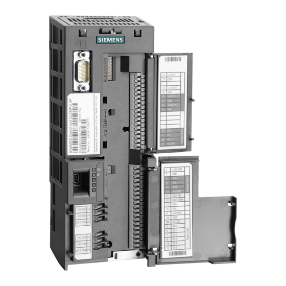
Siemens CU230P-2 HVAC Manual (732 pages)
Brand:
Siemens
| Category:
Control Unit
| Size: 3.69 MB
Table of Contents
Table of Contents
5
Introduction to Parameters
8
Explanation of List of Parameters
8
Siemens AG 2011 All Rights Reserved
8
SINAMICS G120 Control Units CU230P-2 Parameter Manual (LH9)
9
Introduction to Parameters
9
Siemens AG 2011 All Rights Reserved
9
SINAMICS G120 Control Units CU230P-2 Parameter Manual (LH9)
14
Control Units CU230P
15
Function Diagrams
15
SINAMICS G120 Control Units CU230P-2 Parameter Manual (LH9)
15
Faults and Alarms
16
List of Parameters
17
List of Parameters
18
CU230P-2 CAN Access Level
20
Command and Drive Data Sets - Overview
470
Command Data Sets (CDS)
470
Command and Drive Data Sets – Overview
471
Drive Data Sets (DDS)
472
Motor Data Sets (MDS)
477
Power Unit Data Set (PDS)
479
Connector/Binector (BICO)-Parameters
480
Binector Input Parameters
480
Connector/Binector (BICO)-Parameters
481
Connector Input Parameters
482
Binector Output Parameters
484
Connector Output Parameters
486
Connector/Binector Output Parameters
489
Quick Commissioning (P0010 = 1)
491
Quick Commissioning (P0010 = 1)
492
2 Function Diagrams
493
Contents: Function Diagrams
494
Explanations for the Function Diagrams
499
Explanations for the Function Diagrams
500
Explanation of the Symbols (Part)
500
Handling Bico Technology
503
Overview
504
Setpoint Channel
507
Vector Control, V/F Control
508
Vector Control, Speed Control and Generation of the Torque Limits
509
Vector Control, Current Control
510
Monitoring Functions, Faults, Alarms
511
Input/Output Terminals
512
Analog Input 2 (Ai)
517
Temperature Evaluation Ni1000/Pt1000 (Ai)
518
Communication
520
Fieldbus Interface (USS, Modbus, Bacnet) (CU230P-2 HVAC)
521
Stw1 Control Word Interconnection
523
Zsw1 Status Word Interconnection
524
Receive Telegram, Free Interconnection Via Bico
525
Send Telegram, Free Interconnection Via Bico
526
Profidrive / PROFIBUS (CU230P-2 DP)
528
Telegrams and Process Data (Pzd)
530
Pzd Receive Signals Interconnection
531
Pzd Send Signals Interconnection
535
Canopen (CU230P-2 CAN)
542
Control Word, Canopen
547
Status Word, Canopen
548
Internal Control/Status Words
549
Control Word, Sequence Control
550
Status Word, Sequence Control
551
Control Word, Setpoint Channel
552
Control Word, Speed Controller
557
Status Word, Speed Controller
558
Status Word, Closed-Loop Control
559
Status Word, Current Control
560
Control Word, Faults/Alarms
564
Status Word, Faults/Alarms 1 and
565
Sequence Control - Missing Enable Signals
566
Setpoint Channel
567
Main/Supplementary Setpoint, Setpoint Scaling, Jogging
571
Direction Limitation and Direction Reversal
572
Basic Ramp-Function Generator
574
Extended Ramp-Function Generator
575
Ramp-Function Generator Selection, Status Word, Tracking
576
V/F Control
577
V/F Characteristic and Voltage Boost
578
Resonance Damping and Slip Compensation
579
Vector Control
581
Speed Setpoint, Droop
582
Pre-Control Balancing, Acceleration Model
583
Kp_N/Tn_N Adaption
585
Torque Setpoint
586
Speed Control Configuration
588
Flux Control Configuration
589
Upper/Lower Torque Limit
590
Current/Power/Torque Limits
591
Current Setpoint Filter
592
Iq and ID Controllers
593
ID Setpoint (Pem, P0300 = 2Xx)
594
Field Weakening Controller (Pem, P0300 = 2Xx)
597
Control Unit
598
Interface to the Power Module (Pem, P0300 = 2Xx)
599
Display Signals
600
Free Function Blocks
601
Run-Time Groups / Sampling Times
602
Not (Inverter)
606
Add (Adder with 4 Inputs), Sub (Subtracter)
607
Ava (Absolute Value Generators)
609
Ncm (Numerical Comparator)
610
Pli (Scaling Polyline)
611
Mfp (Pulse Generator), Pcl (Pulse Shortener)
612
Pdf (Switch-Out Delay)
614
Pst (Pulse Extender)
615
Rsr (Rs Flipflop), Dfr (D Flipflop)
616
Bsw (Binary Changeover Switch), Nsw (Numerical Changeover Switch)
617
Lim (Limiter)
618
Int (Integrator), Dif (Differentiating Element)
620
Lvm (Limit Value Monitor, Double-Sided with Hysteresis)
621
Technology Functions
622
Technology Functions
623
Free Technology Controller
624
Essential Service Mode
626
Technology Controller
630
Closed-Loop Control
634
Signals and Monitoring Functions
635
Torque Signals, Motor Locked/Stalled
638
Load Monitoring
639
Thermal Monitoring, Power Module
640
Thermal Monitoring, Motor
641
Monitoring Functions
643
Faults and Warnings
645
Fault Buffer
646
Warning Buffer
647
Fault/Warning Trigger Word (R)
648
Fault/Warning Configuration
649
Data Sets
650
Faults and Alarms
653
3 Faults and Alarms
654
Faults and Alarms – Overview
654
General Information
654
Fault Reactions
656
Acknowledgement of Faults
657
List of Faults and Alarms
658
Hardware Limit Has Responded too Often
703
Power Unit: Ground Fault
703
Power Unit: Monitoring U_Ce
703
A.1 ASCII Table (Excerpt)
716
A.2 List for Motor Code
716
Advertisement
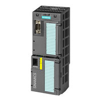
Siemens CU230P-2 HVAC Original Instructions Manual (456 pages)
SINAMICS G120 Inverter with CU230P-2 Control Units
Brand:
Siemens
| Category:
Inverter
| Size: 17.57 MB
Table of Contents
Change History
5
Inverter with CU230P-2 Control Units Operating Instructions, 11/2013, FW V4.6.6, A5E02430659B AG
5
Table of Contents
7
1 Safety Notes
15
General Safety Instructions
15
Safety Instructions for Electromagnetic Fields (EMF)
19
Handling Electrostatic Sensitive Devices (ESD)
19
Residual Risks of Power Drive Systems
20
2 Introduction
23
About this Manual
23
Guide through this Manual
24
3 Description
25
Identifying the Converter
25
Control Units
27
Power Module
28
Power Modules in Degree of Protection IP20 and with Push-Through System
28
Accessories for Installation and Shielding
30
Power Modules in IP55 Degree of Protection / UL Type 12
31
System Components for the Power Modules
32
Line Filter
32
Line Reactor
33
Output Reactor
34
Sine-Wave Filter
36
DV/Dt Filter
37
Braking Module and Braking Resistor
37
Tools to Commission the Converter
39
4 Installing
41
Overview of the Inverter Installation
41
Installing Reactors, Filters and Braking Resistors
42
Installing Power Module
43
Dimensions, Hole Drilling Templates, Minimum Clearances, Tightening Torques
45
Connecting the Line Supply, Motor and Converter Components
51
Power Distribution Systems
54
Installing Control Unit
58
Interfaces, Connectors, Switches, Control Terminals, Leds on the CU
60
Terminal Strips of the CU
62
Selecting the Pre-Assignment for the Terminal Strip
63
Wiring Terminal Strips
66
Connecting Inverters in Compliance with EMC
67
EMC-Compliant Connection of the Converter
67
Avoid Electromagnetic Interference (EMI)
68
5 Commissioning
73
Commissioning Guidelines
73
Preparing for Commissioning
74
Wiring Examples for the Factory Settings
75
Does the Motor Match the Converter
76
Factory Setting of the Converter Control
77
V/F Control or Vector Control (Speed/Torque)
78
Defining Additional Requirements for the Application
79
Restoring the Factory Setting
79
Basic Commissioning
80
Basic Commissioning with the BOP-2 Operator Panel
80
Basic Commissioning with STARTER
85
Adapting Interfaces
86
Generating a STARTER Project
88
Go Online and Start Wizard for Basic Commissioning
88
Carry-Out Basic Commissioning
89
Identifying Motor Data
90
6 Adapting the Terminal Strip
93
Overview
93
Digital Inputs
94
Digital Outputs
96
Analog Inputs
98
Analog Outputs
103
7 Configuring the Fieldbus
107
Communication Via PROFINET
108
What Do You Need for Communication Via PROFINET
108
Connect the Converter to PROFINET
109
Configuring Communication to the Control
110
Select Telegram
110
Activating Diagnostics Via the Control
111
Communication Via PROFIBUS
112
What Do You Need for Communication Via PROFIBUS
112
Connect the Frequency Inverter to PROFIBUS
112
Configuring Communication to the Control
113
Setting the Address
114
Select Telegram
115
Profidrive Profile for PROFIBUS and PROFINET
116
Cyclic Communication
116
Control and Status Word 1
118
Control and Status Word 3
121
Extend Telegrams and Change Signal Interconnection
123
Data Structure of the Parameter Channel
124
Slave-To-Slave Communication
129
Acyclic Communication
130
Profienergy Profile for PROFINET
135
Communication Via Ethernet/Ip
137
Connect Converter to Ethernet/Ip
137
What Do You Need for Communication Via Ethernet/Ip
138
Communication Settings for Ethernet/Ip
138
Additional Settings if You Are Working with the AC/DC Profile
139
Supported Objects
140
Create Generic I/O Module
147
Communication Via RS485
148
Integrating Inverters into a Bus System Via the RS485 Interface
148
Communication Via USS
149
Basic Settings for Communication
149
Telegram Structure
151
User Data Range of the USS Telegram
152
USS Parameter Channel (PIV)
153
USS Process Data Channel (PZD)
158
Time-Out and Other Errors
158
Communication over Modbus RTU
161
Basic Settings for Communication
162
Modbus RTU Telegram
164
Baud Rates and Mapping Tables
164
Write and Read Access Via FC 03 and FC 06
168
Communication Procedure
170
Communication Via Bacnet MS/TP
172
Basic Settings for Communication
173
Supported Services and Objects
174
Communication Via P1
183
Communication over Canopen
188
Canopen Functions of the Converter
188
Network Management (NMT Service)
190
SDO Services
192
Access to SINAMICS Parameters Via SDO
193
Access PZD Objects Via SDO
195
PDO and PDO Services
197
Predefined Connection Set
201
Free PDO Mapping
202
Interconnect Objects from the Receive and Transmit Buffers
205
Canopen Operating Modes
207
Object Directories
207
General Objects from the Cia 301 Communication Profile
207
Free Objects
216
Objects from the Cia 402 Drive Profile
217
Integrating the Converter into Canopen
219
Connecting Inverter to CAN Bus
220
Setting the Node ID and Baud Rate
220
Setting the Monitoring of the Communication
221
Free PDO Mapping for Example of the Actual Current Value and Torque Limit
223
8 Setting Functions
225
Overview of the Inverter Functions
225
Inverter Control
227
Switching the Motor on and off
227
Two-Wire Control: Method 1
230
Two-Wire Control, Method 2
231
Two-Wire Control, Method 3
232
Three-Wire Control, Method 1
233
Three-Wire Control, Method 2
234
Running the Motor in Jog Mode (JOG Function)
235
Switching over the Inverter Control (Command Data Set)
235
Setpoints
238
Analog Input as Setpoint Source
239
Specifying the Motor Speed Via the Fieldbus
239
Motorized Potentiometer as Setpoint Source
240
Fixed Speed as Setpoint Source
242
Setpoint Calculation
244
Overview of Setpoint Processing
244
Invert Setpoint
244
Enable Direction of Rotation
245
Minimum Speed
245
Maximum Speed
246
Ramp-Function Generator
247
Motor Control
250
V/F Control
250
Characteristics of V/F Control
251
Selecting the V/F Characteristic
252
Optimizing with a High Break Loose Torque and Brief Overload
253
Closed-Loop Speed Control
255
Properties of the Sensorless Vector Control
255
Select Motor Control
256
Optimizing the Speed Controller
257
Protection Functions
259
Inverter Temperature Monitoring
259
Motor Temperature Monitoring Using a Temperature Sensor
261
Protecting the Motor by Calculating the Motor Temperature
263
Overcurrent Protection
264
Limiting the Maximum DC Link Voltage
265
Application-Specific Functions
267
Unit Changeover
267
Changing over the Motor Standard
268
Changing over the Unit System
269
Changing over Process Variables for the Technology Controller
269
Switching Units with STARTER
270
Energy-Saving Display
272
Braking Functions of the Converter
273
Electrical Braking Methods
273
DC Braking
275
Compound Braking
278
Dynamic Braking
280
Braking with Regenerative Feedback to the Line
283
Automatic Restart and Flying Restart
284
Flying Restart - Switching on While the Motor Is Running
284
Automatic Switch-On
285
Technology Controller
290
Free Technology Controllers
291
Monitor the Load Torque (System Protection)
291
Load Failure Monitoring
293
Real Time Clock (RTC)
294
Time Switch (DTC)
296
Record Temperature Via Temperature-Dependent Resistances
297
Essential Service Mode
298
Multi-Zone Control
302
Cascade Control
305
Bypass
309
Energy-Saving Mode
313
Logical and Arithmetic Functions Using Function Blocks
318
Switchover between Different Settings
321
9 Backing up Data and Series Commissioning
323
Backing up and Transferring Settings Using a Memory Card
324
Saving Setting on Memory Card
325
Transferring the Setting from the Memory Card
327
Safely Remove the Memory Card
329
Saving Settings on a PC
331
Saving Settings on an Operator Panel
332
Other Ways to Back up Settings
333
Write and Know-How Protection
334
Write Protection
334
Know-How Protection
336
Settings for the Know-How Protection
338
Creating an Exception List for the Know-How Protection
339
Replacing Devices with Active Know-How Protection
340
10 Corrective Maintenance
343
Overview of Replacing Converter Components
343
Replace Control Unit
345
Replacing the Control Unit Without Data Backup
346
Replacing a Power Module
347
Upgrading the Firmware
348
Firmware Downgrade
350
Correcting an Unsuccessful Firmware Upgrade or Downgrade
352
If the Converter no Longer Responds
353
11 Alarms, Faults and System Messages
355
Operating States Indicated on Leds
356
System Runtime
358
Alarms
359
Faults
362
List of Alarms and Faults
366
12 Technical Data
373
Technical Data for CU230P-2
373
Technical Data, Power Modules
375
Technical Data, PM230
376
General Data, PM230 - IP20
377
Power-Dependent Data, PM230, IP20
378
General Data, PM230, IP55
384
Power Dependent Data, PM230, IP55
385
Technical Data, PM240
389
General Data, PM240
390
Power-Dependent Data, PM240
391
Technical Data, PM240-2
395
High Overload - Low Overload PM240-2
395
General Data, PM240-2
396
Power-Dependent Data PM240-2
397
Technical Data, PM250
400
High Overload - Low Overload
400
General Data, PM250
401
Power-Dependent Data, PM250
402
Technical Data, PM260
404
High Overload - Low Overload
404
General Data, PM260
405
Power-Dependent Data, PM260
406
PM330 Technical Data
407
PM330 General Data
407
Power-Dependent Data, PM330
409
Appendix
411
New and Extended Functions
411
Firmware Version 4.6
411
A.1 New and Extended Functions
411
Firmware Version 4.6.6
412
A.1.2 Firmware Version 4.6.6
412
Star-Delta Motor Connection and Application Examples
413
Parameter
414
A.3 Parameter
414
Handling the BOP 2 Operator Panel
417
Changing Settings Using BOP-2
418
Changing Indexed Parameters
419
Directly Entering the Parameter Number and Value
419
A Parameter Cannot be Changed
420
Handling STARTER
421
Change Settings
421
A.5 Handling STARTER
421
Optimize the Drive Using the Trace Function
422
Interconnecting Signals in the Converter
425
Fundamentals
425
Example
427
A.6.2 Example
427
Application Examples
429
Configuring PROFIBUS Communication in STEP 7
429
Creating a STEP 7 Project and Network
429
A.7 Application Examples
429
Inserting the Inverter into the Project
430
Configuring PROFINET Communication in STEP 7
432
Configuring the Controller and Converter in HW Config
432
Create a Reference for STARTERS
435
Call the STARTER and Go Online
436
Activate Diagnostic Messages Via STEP 7
437
STEP 7 Program Examples
438
Data Exchange Via the Fieldbus - CU230
438
STEP 7 Program Example for Cyclic Communication
439
STEP 7 Program Example for Acyclic Communication
440
Configuring Slave-To-Slave Communication in STEP 7
444
Additional Information on the Inverter
446
Manuals for Your Inverter
446
Mistakes and Improvements
448
Index
449
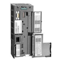
Siemens CU230P-2 HVAC Parameter Manual (668 pages)
SINAMICS G120 Control Units
Brand:
Siemens
| Category:
Control Unit
| Size: 4.42 MB
Table of Contents
3 Faults and Alarms
3
Table of Contents
5
Explanation of List of Parameters
8
Introduction to Parameters
9
Control Units CU230P
13
Introduction to Parameters
8
List of Parameters
15
List of Parameters
16
CU230P-2 CAN Access Level
70
Command and Drive Data Sets - Overview
409
Command Data Sets (CDS)
409
Command and Drive Data Sets – Overview
410
Drive Data Sets (DDS)
411
Motor Data Sets (MDS)
416
Power Unit Data Set (PDS)
418
Binector Input Parameters
419
Connector/Binector (BICO)-Parameters
419
Connector/Binector (BICO)-Parameters
420
Connector Input Parameters
422
Binector Output Parameters
424
Connector Output Parameters
426
Connector/Binector Output Parameters
430
Quick Commissioning (P0010 = 1)
431
Quick Commissioning (P0010 = 1)
432
2 Function Diagrams
433
Contents: Function Diagrams
434
Explanations for the Function Diagrams
439
Overview
444
Input/Output Terminals
452
Communication
460
Fieldbus Interface (USS, Modbus, Bacnet) (CU230P-2 HVAC)
460
Profidrive / PROFIBUS (CU230P-2 DP)
467
Canopen (CU230P-2 CAN)
479
Internal Control/Status Words
486
Setpoint Channel
504
V/F Control
514
Vector Control
518
Free Function Blocks
538
Technology Functions
558
Technology Controller
566
Signals and Monitoring Functions
571
Faults and Warnings
581
Data Sets
586
Faults and Alarms - Overview
590
General Information
590
Fault Reactions
592
List of Faults and Alarms
594
Appendix
651
ASCII Table (Excerpt)
652
List for Motor Code
652
List of Abbreviations
653
Advertisement
Siemens CU230P-2 HVAC Getting Started (56 pages)
for inverter
Brand:
Siemens
| Category:
Control Unit
| Size: 3.9 MB
Table of Contents
Table of Contents
5
1 Safety Information
7
General Safety Instructions
7
Safety Instructions for Electromagnetic Fields (EMF)
11
Handling Electrostatic Sensitive Devices (ESD)
11
Residual Risks of Power Drive Systems
12
2 Design of the Frequency Converter
15
Identifying the Converter
15
Control Units
16
Power Module
17
Assembling Frequency Converter Components
20
IOP Intelligent Operator Panel
21
3 Installing
23
Installing the Power Module
23
Installing Control Unit
26
CU230P-2 Control Unit
26
Interfaces of the CU230P-2
26
Terminal Strips of the CU230P-2
28
CU240B / CU240E Control Unit
29
Interfaces of the CU240B-2 and CU240E-2
29
Terminal Strips on CU240B-2 Control Units
31
Terminal Strips on CU240E-2 Control Units
32
Selecting the Pre-Assignment for the Terminal Strip
33
Wiring the Terminal Strip
41
Description Files for Fieldbuses
42
4 Commissioning
43
Tools to Commission the Converter
43
Commissioning
44
Settings in the Basic Commissioning Menu
45
Enable "Safe Torque Off" Safety Function
46
The most Important Parameters at a Glance
48
5 More Information
53
Manuals for Your Inverter
53
Product Support
54
Advertisement
Related Products
siemens CU250D-2 DP-F
siemens CU250D-2 PN-F
siemens CU250D-2 PN-F PP
siemens CU250D-2 PN-F FO
Siemens CGZ
Siemens CZ
Siemens CGZZ
Siemens CGG
Siemens CAZ
Siemens COMBIMASTER 411
Siemens Categories
Industrial Equipment
Controller
Control Unit
Oven
Washer
More Siemens Manuals
Login
Sign In
OR
Sign in with Facebook
Sign in with Google
Upload manual
Upload from disk
Upload from URL