Delta AS Series Operation Manual
Hide thumbs
Also See for AS Series:
- Programming manual (1381 pages) ,
- Manual (632 pages) ,
- Operation manual (463 pages)
Table of Contents
Advertisement
Send Quote Requests to info@automatedpt.com
Industrial Automation Headquarters
Taiwan:
Delta Electronics, Inc.
Taoyuan Technology Center
No.18, Xinglong Rd., Taoyuan District,
Taoyuan City 33068, Taiwan
TEL: +886-3-362-6301 / FAX: +886-3-371-6301
Asia
China:
Delta Electronics ( Shanghai ) Co., Ltd.
No.182 Minyu Rd., Pudong Shanghai, P.R.C.
Post code : 201209
TEL: +86-21-6872-3988 / FAX: +86-21-6872-3996
Customer Service: 400-820-9595
Delta Electronics ( Japan ) , Inc.
Japan:
Industrial Automation Sales Department
2-1-14 Shibadaimon, Minato-ku
Tokyo, Japan 105-0012
TEL: +81-3-5733-1155 / FAX: +81-3-5733-1255
Delta Electronics ( Korea ) , Inc.
Korea:
1511, 219, Gasan Digital 1-Ro., Geumcheon-gu,
Seoul, 08501 South Korea
TEL: +82-2-515-5305 / FAX: +82-2-515-5302
Delta Energy Systems ( Singapore ) Pte Ltd.
Singapore:
4 Kaki Bukit Avenue 1, #05-04, Singapore 417939
TEL: +65-6747-5155 / FAX: +65-6744-9228
Delta Electronics ( India ) Pvt. Ltd.
India:
Plot No.43, Sector 35, HSIIDC Gurgaon,
PIN 122001, Haryana, India
TEL: +91-124-4874900 / FAX: +91-124-4874945
Thailand:
Delta Electronics ( Thailand ) PCL.
909 Soi 9, Moo 4, Bangpoo Industrial Estate ( E.P.Z ) ,
Pattana 1 Rd., T.Phraksa, A.Muang,
Samutprakarn 10280, Thailand
TEL: +66-2709-2800 / FAX: +66-2709-2827
Delta Electronics ( Australia ) Pty Ltd.
Australia:
Unit 2, Building A, 18-24 Ricketts Road,
Mount Waverley, Victoria 3149 Australia
Mail: IA.au@deltaww.com
TEL: +61-1300-335-823 / +61-3-9543-3720
Americas
USA:
Delta Electronics ( Americas ) Ltd.
5101 Davis Drive, Research Triangle Park, NC 27709, U.S.A.
TEL: +1-919-767-3813 / FAX: +1-919-767-3969
Brazil:
Delta Electronics Brazil Ltd.
Estrada Velha Rio-São Paulo, 5300 Eugênio de
Melo - São José dos Campos CEP: 12247-004 - SP - Brazil
TEL: +55-12-3932-2300 / FAX: +55-12-3932-237
Mexico:
Delta Electronics International Mexico S.A. de C.V.
Gustavo Baz No. 309 Edificio E PB 103
Colonia La Loma, CP 54060
Tlalnepantla, Estado de México
TEL: +52-55-3603-9200
*We reserve the right to change the information in this manual without prior notice.
EMEA
EMEA Headquarters:
Delta Electronics ( Netherlands ) B.V.
Sales: Sales.IA.EMEA@deltaww.com
Marketing: Marketing.IA.EMEA@deltaww.com
Technical Support: iatechnicalsupport@deltaww.com
Customer Support: Customer-Support@deltaww.com
Service: Service.IA.emea@deltaww.com
TEL: +31 ( 0 ) 40 800 3900
Delta Electronics ( Netherlands ) B.V.
BENELUX:
Automotive Campus 260, 5708 JZ Helmond, The Netherlands
Mail: Sales.IA.Benelux@deltaww.com
TEL: +31 ( 0 ) 40 800 3900
Delta Electronics ( Netherlands ) B.V.
DACH:
Coesterweg 45, D-59494 Soest, Germany
Mail: Sales.IA.DACH@deltaww.com
TEL: +49 ( 0 ) 2921 987 0
Delta Electronics ( France ) S.A.
France:
ZI du bois Challand 2, 15 rue des Pyrénées,
Lisses, 91090 Evry Cedex, France
Mail: Sales.IA.FR@deltaww.com
TEL: +33 ( 0 ) 1 69 77 82 60
Delta Electronics Solutions ( Spain ) S.L.U
Iberia:
Ctra. De Villaverde a Vallecas, 265 1º Dcha Ed.
Hormigueras – P.I. de Vallecas 28031 Madrid
TEL: +34 ( 0 ) 91 223 74 20
Carrer Llacuna 166, 08018 Barcelona, Spain
Mail: Sales.IA.Iberia@deltaww.com
Delta Electronics ( Italy ) S.r.l.
Italy:
Via Meda 2–22060 Novedrate ( CO )
Piazza Grazioli 18 00186 Roma Italy
Mail: Sales.IA.Italy@deltaww.com
TEL: +39 039 8900365
Russia:
Delta Energy System LLC
Vereyskaya Plaza II, office 112 Vereyskaya str.
17 121357 Moscow Russia
Mail: Sales.IA.RU@deltaww.com
TEL: +7 495 644 3240
Delta Greentech Elektronik San. Ltd. Sti. ( Turkey )
Turkey:
Şerifali Mah. Hendem Cad. Kule Sok. No:16-A
34775 Ümraniye – İstanbul
Mail: Sales.IA.Turkey@deltaww.com
TEL: + 90 216 499 9910
MEA:
Eltek Dubai ( Eltek MEA DMCC )
OFFICE 2504, 25th Floor, Saba Tower 1,
Jumeirah Lakes Towers, Dubai, UAE
Mail: Sales.IA.MEA@deltaww.com
TEL: +971 ( 0 ) 4 2690148
AS- 0249420 -12
2022/05/30
Call +1(800)985-6929 To Order or Order Online At Deltaacdrives.com
Digitized Automation for a Changing World
AS Series Hardware and
Operation Manual
www.deltaww.com
Send Quote Requests to info@automatedpt.com
Call +1(800)985-6929 To Order or Order Online At Deltaacdrives.com
Advertisement
Table of Contents
Troubleshooting

Related Manuals for Delta AS Series


Summary of Contents for Delta AS Series
- Page 1 Mail: Sales.IA.RU@deltaww.com TEL: +7 495 644 3240 USA: Delta Electronics ( Americas ) Ltd. Delta Greentech Elektronik San. Ltd. Sti. ( Turkey ) 5101 Davis Drive, Research Triangle Park, NC 27709, U.S.A. Turkey: TEL: +1-919-767-3813 / FAX: +1-919-767-3969 Şerifali Mah. Hendem Cad. Kule Sok. No:16-A 34775 Ümraniye –...
- Page 2 Send Quote Requests to info@automatedpt.com Call +1(800)985-6929 To Order or Order Online At Deltaacdrives.com AS Series Hardware and Operation Manual Revision History Ve r s i o n R e v i s i o n D a t e T h e f i r s t v e r s i o n w a s p u b l i s h e d .
- Page 3 Send Quote Requests to info@automatedpt.com Call +1(800)985-6929 To Order or Order Online At Deltaacdrives.com Ve r s i o n R e v i s i o n D a t e a s t r o u b l e s h o o t i n g . 1 7 .
- Page 4 Send Quote Requests to info@automatedpt.com Call +1(800)985-6929 To Order or Order Online At Deltaacdrives.com Ve r s i o n R e v i s i o n D a t e A H C P U 5 6 0 - E N 2 i n s e c t i o n 9 . 9 . 2 5 .
- Page 5 Send Quote Requests to info@automatedpt.com Call +1(800)985-6929 To Order or Order Online At Deltaacdrives.com Ve r s i o n R e v i s i o n D a t e 1 6 . U p d a t e d t h e E t h e r N e t / I P s p e c i f i c a t i o n t a b l e i n s e c t i o n 9 .
- Page 6 Send Quote Requests to info@automatedpt.com Call +1(800)985-6929 To Order or Order Online At Deltaacdrives.com Ve r s i o n R e v i s i o n D a t e 2 0 2 1 0 2 2 5 1 .
- Page 7 Send Quote Requests to info@automatedpt.com Call +1(800)985-6929 To Order or Order Online At Deltaacdrives.com Ve r s i o n R e v i s i o n D a t e m o d u l e . ” i n s e c t i o n 1 2 . 4 . 5 . 1 1 .
-
Page 8: Table Of Contents
Send Quote Requests to info@automatedpt.com Call +1(800)985-6929 To Order or Order Online At Deltaacdrives.com AS Series Hardware and Operation Manual Table of Contents Chapter 1 Product Introduction Overview ................... 1-2 1.1.1 Related Manuals ................1-2 1.1.2 Models Descriptions ............... 1-2 Overview .................. - Page 9 Send Quote Requests to info@automatedpt.com Call +1(800)985-6929 To Order or Order Online At Deltaacdrives.com 2.6.2 Positioning Module Profiles ............2-61 2.6.3 Positioning Module Terminals ............2-62 Counter Module Specifications ............2-63 2.7.1 General Specifications ..............2-63 2.7.2 Counting Module Profiles ............... 2-66 2.7.3 Counting Module Terminals ............
- Page 10 Wiring AS132T-A/AS148T-A/AS164T-A ........... 4-40 4.6.11 Wiring AS132P-A/AS148P-A/AS164P-A ........... 4-41 4.6.12 Wiring AS132R-A/AS148R-A/AS164R-A .......... 4-42 4.6.13 Wiring AS Series PLC CPU Communication Ports ......4-43 Wiring Digital Input/Output Modules ..........4-47 4.7.1 Wiring AS08AM10N-A ..............4-47 4.7.2 Wiring AS08AN01P-A ..............4-48 4.7.3...
- Page 11 Send Quote Requests to info@automatedpt.com Call +1(800)985-6929 To Order or Order Online At Deltaacdrives.com 4.7.8 Wiring AS16AN01P-A ..............4-54 4.7.9 Wiring AS16AP11R-A ..............4-55 4.7.10 Wiring AS16AP11T-A ..............4-56 4.7.11 Wiring AS16AP11P-A ..............4-57 4.7.12 Wiring AS32AM10N-A ..............4-58 4.7.13 Wiring AS32AN02T-A ..............
- Page 12 Send Quote Requests to info@automatedpt.com Call +1(800)985-6929 To Order or Order Online At Deltaacdrives.com 4.14.4 Wiring AS-F2AD ................ 4-106 4.14.5 Wiring AS-F2DA ................ 4-107 Chapter 5 Devices 5.1 Introduction of Devices ................. 5-2 5.1.1 Device Table ................5-2 5.1.2 Basic Structure of I/O Storages ............5-3 5.1.3 Relation Between the PLC Action and the Device Type ......
- Page 13 Send Quote Requests to info@automatedpt.com Call +1(800)985-6929 To Order or Order Online At Deltaacdrives.com 5.5.3 Starting Addresses for Temperature Measurement Modules ....5-33 5.5.4 Starting Addresses for Load Cell Modules ..........5-33 5.5.5 Starting Addresses for AS04SIL-A Modules ........... 5-34 Chapter 6 Writing a Program Quick Start ..................
- Page 14 Restoration Starts Once CPU is supplied with Power ....... 7-19 CPU Error Log .................. 7-20 Chapter 8 Hardware Configuration and Data Exchange Setups Hardware Configuration Tool for AS Series Modules - HWCONFIG ..8-2 8.1.1 Introduction of the HWCONFIG Environment .......... 8-2 8.1.2 Configuring a Module ................8-4 Setting the Parameters in an AS Series CPU Module ......
- Page 15 Send Quote Requests to info@automatedpt.com Call +1(800)985-6929 To Order or Order Online At Deltaacdrives.com 8.2.12 Ethernet Port Advance Setting – Socket ..........8-41 8.2.13 Ethernet Port Advance Setting – RTU Mapping ........8-43 8.2.14 Function Card 1 Setting ..............8-44 8.2.15 Function Card 2 Setting ..............
- Page 16 9.8.19 SR Register (Class ID: 359 Hex) ............. 9-102 Delta EIP Product List ..............9-103 9.9.1 Delta EIP Products ................. 9-103 9.9.2 Delta EIP Products, DLR (Device Level Ring) supported ....... 9-103 9.9.3 Delta EIP Products, Scanner supported ..........9-104 9.10 Network Security ................
- Page 17 Send Quote Requests to info@automatedpt.com Call +1(800)985-6929 To Order or Order Online At Deltaacdrives.com Chapter 10 CANopen Funciton and Operation 10.1 Introduction to CANopen ..............10-2 10.1.1 CANopen Function Descriptions ............10-2 10.1.2 The Input/Output Mapping Areas ........... 10-4 10.1.3 Refreshing Mechanism in the Input/Output Mapping Areas ....
- Page 18 Send Quote Requests to info@automatedpt.com Call +1(800)985-6929 To Order or Order Online At Deltaacdrives.com Chapter 12 Troubleshooting 12.1 Troubleshooting ................12-3 12.1.1 Basic troubleshooting steps ............12-3 12.1.2 Clear the Error States ..............12-3 12.1.3 Troubleshooting SOP ..............12-4 12.1.4 Viewing System Log and Error Step ..........
- Page 19 A.1 Installing the USB Driver for an AS Series CPU module in Windows XP with SP3 ....................A-2 A.2 Installing the USB Driver for an AS Series CPU module in Windows 7 ... A-6 A.3 Installing the USB Driver for an AS Series CPU module in Windows 8 . A-11 A.4 Installing the USB Driver for an AS Series CPU module in Windows 10A-13...
- Page 20 B.2 Function Codes and Number of Devices Supported for Modbus ProtocolsB-3 Appendix C EMC Standards C.1 EMC Standards for an AS Series System ..........C-2 C.1.1 AS Series System EMC Standards ............C-2 C.1.2 Installation Instructions to meet EMC Standards ........C-4 C.1.3 Cables ....................
- Page 21 Send Quote Requests to info@automatedpt.com Call +1(800)985-6929 To Order or Order Online At Deltaacdrives.com Chapter 1 Product Introduction Table of Contents Overview ................... 1-2 1.1.1 Related Manuals ................1-2 1.1.2 Models Descriptions ............... 1-2 Overview ..................1-13 Characteristics ................. 1-14 Send Quote Requests to info@automatedpt.com Call +1(800)985-6929 To Order or Order Online At Deltaacdrives.com...
-
Page 22: Overview
Call +1(800)985-6929 To Order or Order Online At Deltaacdrives.com 1.1 Overview This manual introduces the AS Series PLC CPU functions, devices, module tables, basic instructions, applied instructions, electrical specifications troubleshooting, as well as appearances, dimensions, and so forth. 1.1.1 Related Manuals The related manuals for AS Series programmable logic controllers are listed below. - Page 23 Send Quote Requests to info@automatedpt.com Call +1(800)985-6929 To Order or Order Online At Deltaacdrives.com Classification Model Name Description (16DI+16DO) and up to 1024 I/Os. Program capacity:128K steps, high-density terminal blocks CPU module, 24VDC power input, NPN differential output, 1x Ethernet port, 2x RS-485 ports, 1x USB port, 1x Micro AS324MT-A SD interface, 2x function cards (optional), supporting 24 I/Os (12DI+12DO) and up to 1016 I/Os.
- Page 24 Send Quote Requests to info@automatedpt.com Call +1(800)985-6929 To Order or Order Online At Deltaacdrives.com Classification Model Name Description steps, removable terminal blocks CPU module, 24VDC power input, PNP output, 1x Ethernet port , 2x RS-485 ports, 1x USB port, 1x Micro SD interface, AS218PX-A CAN communication port, supporting 18 I/Os (8DI+6DO+2AI+2AO) and up to 1024 I/Os.
- Page 25 Send Quote Requests to info@automatedpt.com Call +1(800)985-6929 To Order or Order Online At Deltaacdrives.com Classification Model Name Description steps, removable terminal blocks CPU module, 100-240VDC power input, NPN output, 1x Ethernet port , 2x RS-485 ports, 1x USB port, 1x Micro SD AS148T-A interface, CAN communication port, supporting 48 I/Os (24DI+24DO) and up to 1024 I/Os.
- Page 26 Send Quote Requests to info@automatedpt.com Call +1(800)985-6929 To Order or Order Online At Deltaacdrives.com Classification Model Name Description 240VAC/24VDC 2A/output, 8A/COM AS08AN01R-A 8 outputs Relay Spring-clamp terminal block 5 - 30VDC 0.5A/output, 4A/COM AS08AN01T-A 8 outputs Sinking output Spring-clamp terminal block 24VDC AS16AM10N-A 16 inputs...
- Page 27 Send Quote Requests to info@automatedpt.com Call +1(800)985-6929 To Order or Order Online At Deltaacdrives.com Classification Model Name Description 5 - 30VDC 0.5A/output, 4A/COM 8 outputs Sourcing output Spring-clamp terminal block 24VDC 8 inputs 240VAC/24VDC AS16AP11R-A 2A/output, 8A/COM 8 outputs Relay Spring-clamp terminal block 24VDC 8 inputs...
- Page 28 Send Quote Requests to info@automatedpt.com Call +1(800)985-6929 To Order or Order Online At Deltaacdrives.com Classification Model Name Description 64 inputs MIL connector 5 - 30VDC 0.1A/output, 3.2A/COM AS64AN02T-A 64 outputs Sinking output MIL connector 4-channel analog input module Hardware resolution: 16 bits 0–10V, 0/1–5V, -5 to +5V, -10 to +10V, 0/4–20mA, -20–...
- Page 29 Send Quote Requests to info@automatedpt.com Call +1(800)985-6929 To Order or Order Online At Deltaacdrives.com Classification Model Name Description 2-channel analog output Hardware resolution: 12 bits -10 to +10V, 0–20mA, 4–20mA Conversion time: 2 ms/channel 2-channel analog input Hardware resolution: 16 bits 0–10V, 0/1–5V, -5 to +5V, -10 to +10V, 0/4–20mA, -20 to +20mA AS02ADH-A...
- Page 30 Send Quote Requests to info@automatedpt.com Call +1(800)985-6929 To Order or Order Online At Deltaacdrives.com Classification Model Name Description module Eigenvalues for a load cell: 1, 2, 4, 6, 20, 40, 80 mV/V Highest precision 1/10000 @ 50ms of conversion time ADC Resolution : 4 bits Conversion time: 2.5–400ms (nine options to choose from) 2-axis motion control...
- Page 31 Serial communication port, RS485, functioning as master or AS-F485 slave CANopen communication port, supporting DS301, AS AS-FCOPM series remote modules and Delta servo systems 2-channel analog input AS-F2AD 0-10V (12 bits), 4-20mA (11 bits) Conversion time: 3ms/channel 2-channel analog output...
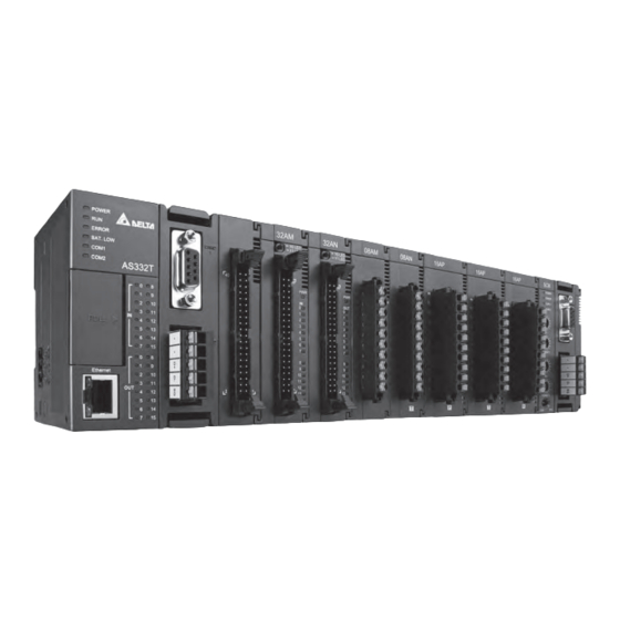
- Page 32 Send Quote Requests to info@automatedpt.com Call +1(800)985-6929 To Order or Order Online At Deltaacdrives.com Classification Model Name Description Use for the connection between a PLC and a PC with a mini UC-PRG030-01A (3M) USB port, use for AS332T-A, AS332P-A, and AS324MT-A Use for the connection between a PLC and a PC with a UC-PRG030-20A (3M) RJ45 port, use for AS332T-A, AS332P-A, AS324MT-A, AS-...
-
Page 33: Overview
1.2 Overview An AS series CPU module is an advanced controller with built-in 6 high speed counters for inputs, up to 6-axis (pulse), and can optionally work with a total of 8-axis (CANopen) position outputs. It provides a strong network function for users, and users can create connection among devices on the network through software. -
Page 34: Characteristics
200 kHz (differential output models can reach 4 MHz). Supporting more inputs and outputs The AS series CPU module supports up to 1024 digital I/Os or 32 I/O modules (any type) or 16 analog I/O modules. - Page 35 Strong function block Both standard IEC61131-3 function blocks and convenient functions blocks provided by Delta Electronics, Inc. are supported. You can use function blocks for frequently used programs for greater structure and convenience.
- Page 36 Increasing hardware configuration efficiency through a USB cable and ISPSoft / DIADesigner The AS Series CPU module provides a standard USB 2.0 interface. USB 2.0 increases the data transfer rate and decreases the time it takes to download the program, monitor the program, and configure the hardware.
- Page 37 (13) Supporting on-line debugging mode You can use the on-line debugging mode in the AS series CPU module after a single instruction step completes, or after a breakpoint is specified, to find bugs in the program.
- Page 38 Send Quote Requests to info@automatedpt.com Call +1(800)985-6929 To Order or Order Online At Deltaacdrives.com Using ISPSoft to demonstrate: Step 1: Set the PLC to RUN Step 2: Entering the on-line mode Send Quote Requests to info@automatedpt.com Call +1(800)985-6929 To Order or Order Online At Deltaacdrives.com...
- Page 39 Send Quote Requests to info@automatedpt.com Call +1(800)985-6929 To Order or Order Online At Deltaacdrives.com Step 3: Enter debugging mode (14) On-line editing mode You can use the on-line editing mode when the system is running to update the program without affecting the system operation.
- Page 40 Send Quote Requests to info@automatedpt.com Call +1(800)985-6929 To Order or Order Online At Deltaacdrives.com After the program is modified and compiled, you can update the program in the CPU module by clicking to download it to the CPU. Send Quote Requests to info@automatedpt.com Call +1(800)985-6929 To Order or Order Online At Deltaacdrives.com...
-
Page 41: Chapter 2 Specifications And System Configuration
Send Quote Requests to info@automatedpt.com Call +1(800)985-6929 To Order or Order Online At Deltaacdrives.com Chapter 2 Specifications and System Configuration Table of Contents General Specifications ............... 2-3 CPU Module Specifications ..............2-4 2.2.1 Functional specifications ..............2-4 2.2.2 Electrical specifications ..............2-5 2.2.3 CPU Module Profiles .............. - Page 42 Send Quote Requests to info@automatedpt.com Call +1(800)985-6929 To Order or Order Online At Deltaacdrives.com 2.10.3 Function Card Weights ..............2-89 2.11 Power Supply Module Specifications ..........2-90 2.11.1 General Specifications ..............2-90 2.11.2 Power Supply Module Profiles ............2-91 2.12 Power Supply Module Adapter Specification ........
-
Page 43: General Specifications
Send Quote Requests to info@automatedpt.com Call +1(800)985-6929 To Order or Order Online At Deltaacdrives.com 2.1 General Specifications Item Specifications Operating temperature -20 to 60°C Storage temperature -40 to 80°C 5–95% Operating humidity No condensation 5–95% Storage humidity No condensation Work environment No corrosive gas exists. -
Page 44: Cpu Module Specifications
No backplane installation; only module after module Maximum number of modules which can be 32 modules installed Refer to the AS Series 283 tasks (32 cyclic tasks; 16 I/O interrupts; four Number of tasks Operation manual for timed interrupts, etc.) more information. -
Page 45: Electrical Specifications
Send Quote Requests to info@automatedpt.com Call +1(800)985-6929 To Order or Order Online At Deltaacdrives.com AS164T-A / AS164R-A AS164P-A / AS148T-A AS148R-A / AS148P-A AS324MT-A / AS332T-A / AS132T-A / AS132R-A Item Remark AS332P-A AS132P-A AS228T-A / AS228P-A AS228R-A / AS218TX-A AS218PX-A / AS218RX-A Index register [E] 10 (E0–E9) - Page 46 Send Quote Requests to info@automatedpt.com Call +1(800)985-6929 To Order or Order Online At Deltaacdrives.com AS100 Series AS132T-A AS148T-A AS164T-A Model AS132R-A AS148R-A AS164R-A AS132P-A AS148P-A AS164P-A Item Supply voltage 100 ~ 240VAC (-15% ~ 10%); 50 / 60Hz ± 5% Max.
- Page 47 Send Quote Requests to info@automatedpt.com Call +1(800)985-6929 To Order or Order Online At Deltaacdrives.com Model AS332T-A AS320T-B AS324MT-A AS332P-A AS320P-B Item X0.0+–X0.3+/X0.0- to X0.0~X0.11: < 2.5μs X0.3-: < 0.125 μs ON→OFF X0.12~X0.15: < 50μs X0.4–X0.11: < 2.5μs X0.0+–X0.3+/X0.0- to Maximum input X0.0~X0.11: 200 kHz X0.3-: <...
- Page 48 Send Quote Requests to info@automatedpt.com Call +1(800)985-6929 To Order or Order Online At Deltaacdrives.com AS200 Series: Electrical specifications for the inputs. The signals passing through the inputs are 24 VDC signals. Model AS228P-A / AS228R-A / AS228T-A AS218PX-A / AS218RX-A / AS218TX-A Item Number of inputs 16 (X0.0-X0.15)
- Page 49 Send Quote Requests to info@automatedpt.com Call +1(800)985-6929 To Order or Order Online At Deltaacdrives.com AS200 Series: Electrical specifications for the outputs AS228R-A AS228T-A AS228P-A Model Item AS218RX-A AS218TX-A AS218PX-A AS228 Series: 12 outputs (Y0.0-Y0.11) Number of outputs AS218 Series 6 outputs (Y0.0-Y0.5) Terminal connector type Removable spring-type terminal blocks Transistor-P...
- Page 50 Send Quote Requests to info@automatedpt.com Call +1(800)985-6929 To Order or Order Online At Deltaacdrives.com AS100 Series: Electrical specifications for the inputs. The signals passing through the inputs are 24 VDC signals. AS164T-A AS148T-A AS132T-A Model AS164P-A AS148P-A AS132P-A Item AS164R-A AS148R-A AS132R-A...
- Page 51 Send Quote Requests to info@automatedpt.com Call +1(800)985-6929 To Order or Order Online At Deltaacdrives.com AS164R-A AS164T-A AS164P-A Model AS148R-A AS148T-A AS148P-A Item AS132R-A AS132T-A AS132P-A 20W (24 VDC) Bulb 2.5W (30 VDC) 100W (230 VAC) Maximum output Y0.0~Y0.11: 200 kHz 1 Hz frequency Y0.12~*...
-
Page 52: Cpu Module Profiles
Send Quote Requests to info@automatedpt.com Call +1(800)985-6929 To Order or Order Online At Deltaacdrives.com 2.2.3 CPU Module Profiles AS324MT-A/AS332T-A/AS332P-A/AS300N-A POWE R ERROR BAT. LOW COM1 COM2 AS324MT Ethernet Unit: mm AS320T-B/AS320P-B 9 5 .5 Unit: mm Number Name Description Power LED indicator Indicates the power status of the CPU module Operating status of the module... - Page 53 Send Quote Requests to info@automatedpt.com Call +1(800)985-6929 To Order or Order Online At Deltaacdrives.com Number Name Description SD card slot Provides an interface for an SD card VR0: use the flag SM166 to activate the values in SR166 VR0/VR1 VR1: use the flag SM167 to activate the values in SR167 Input/Output LED If there is an input signal, the input LED indicator is ON.
- Page 54 Send Quote Requests to info@automatedpt.com Call +1(800)985-6929 To Order or Order Online At Deltaacdrives.com Number Name Description Model name Shows the model name of the CPU module. RUN: execute the programs Run/Stop STOP: stop the programs USB port Mini USB communication port SD card slot Provides an interface for an SD card VR0: use the flag SM166 to activate the values in SR166...
- Page 55 Send Quote Requests to info@automatedpt.com Call +1(800)985-6929 To Order or Order Online At Deltaacdrives.com Number Name Description SD card slot Provides an interface for an SD card RUN: execute the programs Run/Stop STOP: stop the programs Power LED Indicates the power status of the CPU module indicator Operating status of the module ON: the module is running.
- Page 56 Send Quote Requests to info@automatedpt.com Call +1(800)985-6929 To Order or Order Online At Deltaacdrives.com AS332T-A/AS332P-A/AS324MT-A and the external terminal module UB-10-ID16A 67.0 87.0 53.6 Unit: mm Number Name Description 20-pin MIL connector Connects the external terminal module and a wiring module Terminals Input/Output terminals for wiring Clip...
- Page 57 Send Quote Requests to info@automatedpt.com Call +1(800)985-6929 To Order or Order Online At Deltaacdrives.com Spring clamp/MIL connector terminal block UB-10-IO32D for AS332T-A/AS332P-A/AS324MT-A 24 35 23 6 . 26.9 33.7 Unit: mm Number Name Description Terminal block for output Terminal block 40-pin MIL connector Connects the module and the wiring module Note: It is suggested to use simple test for input and output points.
-
Page 58: Cpu Module Input/Output Terminals
Send Quote Requests to info@automatedpt.com Call +1(800)985-6929 To Order or Order Online At Deltaacdrives.com 2.2.4 CPU Module Input/Output Terminals AS300 Series PLC CPU AS332P-A AS332T-A X0.15 X0.14 X0.15 X0.14 X0.13 X0.12 X0.13 X0.12 X0.11 X0.10 X0.11 X0.10 X0.9 X0.8 X0.9 X0.8 POWER... - Page 59 Send Quote Requests to info@automatedpt.com Call +1(800)985-6929 To Order or Order Online At Deltaacdrives.com AS200 Series PLC CPU AS218RX-A/AS218TX-A/AS218PX-A POWER R UN ERROR BAT. LOW X0.0 Y0.0 C OM1 C OM2 VI1- VI2- X0.1 Y0.1 X0.2 Y0.2 X0.3 ● ●...
- Page 60 Send Quote Requests to info@automatedpt.com Call +1(800)985-6929 To Order or Order Online At Deltaacdrives.com AS100 Series PLC CPU AS132T-A/AS132P-A/AS132R-A (16DI/16DO) POWER ERROR BAT. LOW 12 13 14 ● ● COM1 COM2 STOP 9 10 11 12 13 14 15 AS132T Micro SD 9 10 11 12 13 14 15...
- Page 61 Send Quote Requests to info@automatedpt.com Call +1(800)985-6929 To Order or Order Online At Deltaacdrives.com AS164T-A/AS164P-A/AS164R-A(32DI / 32DO) POWER ERROR BAT. LOW ● 12 13 14 12 13 14 ● ● ● COM1 COM2 STOP 9 10 11 12 13 14 15 AS164T 9 10 11 12 13 14 15 Micro SD...
- Page 62 Send Quote Requests to info@automatedpt.com Call +1(800)985-6929 To Order or Order Online At Deltaacdrives.com AS332P-A Y0.0 Y0.2 Y0.4 Y0.6 Y0.8 Y0.10 Y0.12 Y0.14 Y0.1 Y0.3 Y0.5 Y0.7 Y0.9 Y0.11 Y0.13 Y0.15 X0.0 X0.2 X0.4 X0.6 X0.8 X0.10 X0.12 X0.14 X0.1 X0.3 X0.5 X0.7...
-
Page 63: As200 Input/Output Terminals
Send Quote Requests to info@automatedpt.com Call +1(800)985-6929 To Order or Order Online At Deltaacdrives.com 2.2.5 AS200 Input/Output Terminals Analog Input Two analog signal input channels: Item Voltage Input Current input -20 to 20 mA Analog Signal -10 to +10 V 4 to 20mA (for FW V1.08 or later) Resolution 12-bit... -
Page 64: Digital Input/Output Module Specifications
Send Quote Requests to info@automatedpt.com Call +1(800)985-6929 To Order or Order Online At Deltaacdrives.com 2.3 Digital Input/Output Module Specifications 2.3.1 General Specifications Electrical specifications for the inputs on digital input/output modules (The signals passing through the inputs are 24 VDC signals.) 08AM10N 16AM10N 32AM10N... - Page 65 Send Quote Requests to info@automatedpt.com Call +1(800)985-6929 To Order or Order Online At Deltaacdrives.com Electrical specifications for the outputs on a digital input/output module Model 08AN01 16AN01 16AP11 08AN01 16AN01 16AP11 08AN01 16AN01 16AP11 Item Number of outputs Connector type Removable terminal block Output type Digital output...
- Page 66 Send Quote Requests to info@automatedpt.com Call +1(800)985-6929 To Order or Order Online At Deltaacdrives.com Model 32AN02T-A 64AN02T-A Item Weight 100 g 142 g *1: The scan cycle affects the frequency. Here shows the maximum output frequency. The load type should be taken into account while designing for the application. *2: Life cycle curve: The lifetime of a relay terminal varies with the working voltage, the load type (the power factor cosψ, the time constant t(L/R)), and the current passing through the terminal.
-
Page 67: Digital Input/Output Module Profiles
Send Quote Requests to info@automatedpt.com Call +1(800)985-6929 To Order or Order Online At Deltaacdrives.com 2.3.2 Digital Input/Output Module Profiles AS08AM10N-A/AS08AN01P-A/AS08AN01R-A/AS08AN01T-A 28.2 08AM 08AN 08AN 08AN Unit: mm Number Name Description Model name Model name of the module If there is an input signal, the input LED indicator is ON. Input/output LED indicator If there is an output signal, the output LED indicator is ON. - Page 68 Send Quote Requests to info@automatedpt.com Call +1(800)985-6929 To Order or Order Online At Deltaacdrives.com AS16AM10N-A/AS16AN01P-A/AS16AN01R-A/AS16AN01T-A/AS16AP11P-A/AS16AP11R-A/ AS16AP11T-A 38.2 16AM 16AN 16AN 16AN 16AP 16 AP 16AP Unit: mm Number Name Description Model name Model name of the module If there is an input signal, the input LED indicator is ON. Input/Output LED indicator If there is an output signal, the output LED indicator is ON.
- Page 69 Send Quote Requests to info@automatedpt.com Call +1(800)985-6929 To Order or Order Online At Deltaacdrives.com AS32AM10N-A 28.2 32AM X0 LED X1 LED Unit: mm Number Name Description Model name Model name of the module X0/X1 LED Switches the LED indicators to their represented inputs. Indicator switch For the external I/O connecting cables UC-ET010-24B, UC-ET020-24B, ML connector...
- Page 70 Send Quote Requests to info@automatedpt.com Call +1(800)985-6929 To Order or Order Online At Deltaacdrives.com AS32AN02T-A 28.2 32AN Y0 LED Y1 LED Unit: mm Number Name Description Model name Model name of the module Y0/Y1 LED Switches the LED indicators to their represented outputs. indicator switch For the external I/O connecting cables UC-ET010-24D, UC-ET020-24D, ML connector...
- Page 71 Send Quote Requests to info@automatedpt.com Call +1(800)985-6929 To Order or Order Online At Deltaacdrives.com AS64AM10N-A 38.2 64AM P WR Unit: mm Number Name Description Model name Model name of the module LED indicator Switches the LED indicators to their represented inputs. switch 1 LED indicator Switches the LED indicators to their represented inputs.
- Page 72 Send Quote Requests to info@automatedpt.com Call +1(800)985-6929 To Order or Order Online At Deltaacdrives.com AS64AN02T-A 38.2 64AN P WR O UT Unit: mm Number Name Description Model name Model name of the module LED indicator Switches the LED indicators to their represented outputs. switch 1 LED indicator Switches the LED indicators to their represented outputs.
- Page 73 Send Quote Requests to info@automatedpt.com Call +1(800)985-6929 To Order or Order Online At Deltaacdrives.com ML connector, extension cable, and wiring modules Extension Cable UC-ET010-24D (1M) / UC-ET020-24D (2M) / UC-ET030-24D (3M) Length 19 2 0 3 9 40 39 40 21 2 2 500 +10m m Unit: mm...
- Page 74 Send Quote Requests to info@automatedpt.com Call +1(800)985-6929 To Order or Order Online At Deltaacdrives.com UB-10-ID32A 53.6 Unit: mm Number Name Description UB-10-ID16A: 20-pin ML connector Connects the external terminal module and a wiring module UB-10-ID32A: 40-pin ML connector Terminals Input/Output terminals for wiring Clip Hangs the external terminal module on a DIN rail...
- Page 75 Send Quote Requests to info@automatedpt.com Call +1(800)985-6929 To Order or Order Online At Deltaacdrives.com UB-10-OT32A 53.6 Unit: mm Number Name Description UB-10- ID16A /OR16A: 20- pin ML connector Connects the external terminal module and a wiring module UB-10-OT32A: 40-pin ML connector Terminals Input/Output terminals for wiring...
-
Page 76: Digital Input/Output Module Terminals
Send Quote Requests to info@automatedpt.com Call +1(800)985-6929 To Order or Order Online At Deltaacdrives.com 2.3.3 Digital Input/Output Module Terminals AS08AM10N-A AS08AN01P-A 08AN 08AM AS08AN01R-A AS08AN01T-A 08AN 08AN Send Quote Requests to info@automatedpt.com Call +1(800)985-6929 To Order or Order Online At Deltaacdrives.com... - Page 77 Send Quote Requests to info@automatedpt.com Call +1(800)985-6929 To Order or Order Online At Deltaacdrives.com AS16AM10N-A AS16AN01P-A 16AM 16AN AS16AN01R-A AS16AN01T-A 16AN 16AN Send Quote Requests to info@automatedpt.com Call +1(800)985-6929 To Order or Order Online At Deltaacdrives.com...
- Page 78 Send Quote Requests to info@automatedpt.com Call +1(800)985-6929 To Order or Order Online At Deltaacdrives.com AS16AP11P-A AS16AP11R-A 16AP 16AP AS16AP11T-A AS32AM10N-A 1.15 1.14 32AM 16AP 1.13 1.12 X0 LED X1 LED 1.11 1.10 0.15 0.14 0.13 0.12 0.11 0.10 Send Quote Requests to info@automatedpt.com Call +1(800)985-6929 To Order or Order Online At Deltaacdrives.com...
- Page 79 Send Quote Requests to info@automatedpt.com Call +1(800)985-6929 To Order or Order Online At Deltaacdrives.com AS32AN02T-A AS64AM10N-A S/S0 S/S0 32AN 64AM 1.15 1.14 1.15 1.14 Y0 LED 1.13 1.12 1.13 1.12 Y1 LED 1.11 1.10 1.11 1.10 2.10 2.11 2.12 2.13 2.14 2.15 S/S0...
- Page 80 X0.13 X0.15 The wiring module: UB-10-ID32A AS series terminals: Upper X0.0 X0.2 X0.4 X0.6 X0.8 X0.10 X0.12 X0.14 X1.0 X1.2 X1.4 X1.6 X1.8 X1.10 X1.12 X1.14 S/S S/S Lower X0.1 X0.3 X0.5 X0.7 X0.9 X0.11 X0.13 X0.15 X1.1 X1.3 X1.5 X1.7 X1.9 X1.11 X1.13 X1.15 S/S S/S Send Quote Requests to info@automatedpt.com...
- Page 81 Y0.9 Y0.11 Y0.13 Y0.15 UB-10-OT32A AS series terminals: Upper Y0.0 Y0.2 Y0.4 Y0.6 Y0.8 Y0.10 Y0.12 Y0.14 Y1.0 Y1.2 Y1.4 Y1.6 Y1.8 Y1.10 Y1.12 Y1.14 Lower Y0.1 Y0.3 Y0.5 Y0.7 Y0.9 Y0.11 Y0.13 Y0.15 Y1.1 Y1.3 Y1.5 Y1.7 Y1.9 Y1.11 Y1.13 Y1.15 ...
- Page 82 Send Quote Requests to info@automatedpt.com Call +1(800)985-6929 To Order or Order Online At Deltaacdrives.com AS32AM10N-A/AS32AN02T-A and the wiring modules: UB-10-IO32D Send Quote Requests to info@automatedpt.com Call +1(800)985-6929 To Order or Order Online At Deltaacdrives.com...
-
Page 83: Analog Input/Output Module Specifications
Send Quote Requests to info@automatedpt.com Call +1(800)985-6929 To Order or Order Online At Deltaacdrives.com 2.4 Analog Input/Output Module Specifications 2.4.1 General Specifications AS04AD-A / AS08AD-B / AS08AD-C Electrical specifications Module Name AS04AD-A AS08AD-B AS08AD-C Number of Inputs Analog-to-Digital Voltage input/Current input Voltage input Current input Conversion... - Page 84 Send Quote Requests to info@automatedpt.com Call +1(800)985-6929 To Order or Order Online At Deltaacdrives.com Analog-to-Digital Current Input Conversion Rated Input Range ±20 mA 0 mA–20 mA 4 mA–20 mA K-32000 Rated Conversion Range K+2000 K32000 K32000 Hardware Input -20.24 mA ~ 20.24 mA -0.24 mA ~ 20.24 mA 3.81 mA ~ 20.19 mA Limit*...
- Page 85 Send Quote Requests to info@automatedpt.com Call +1(800)985-6929 To Order or Order Online At Deltaacdrives.com Functional specifications Digital-to-analog Voltage output conversion Rated output ±10 V 0 V–10 V ±5 V 0 V–5 V 1 V–5 V range K-32000 K-32000 Conversion Range K+32000 K32000 K+32000...
- Page 86 Send Quote Requests to info@automatedpt.com Call +1(800)985-6929 To Order or Order Online At Deltaacdrives.com AS06XA-A Electrical specifications Module name AS06XA-A Number of Inputs: four; Outputs: two inputs/outputs Analog-to-digital Voltage input/Current input; Voltage output/Current output; conversion Supply voltage 24 VDC (20.4 VDC–28.8 VDC) (-15% to +20%) Connector type Removable terminal block Conversion time...
- Page 87 Send Quote Requests to info@automatedpt.com Call +1(800)985-6929 To Order or Order Online At Deltaacdrives.com Analog-to-Digital Current Input Conversion Rated Input Range ±20 mA 0 mA–20 mA 4 mA–20 mA K-32000 Rated Conversion Range K+2000 K32000 K32000 Hardware Input -20.24 mA ~ 20.24 mA -0.24 mA ~ 20.24 mA 3.81 mA ~ 20.19 mA Limit*...
- Page 88 Send Quote Requests to info@automatedpt.com Call +1(800)985-6929 To Order or Order Online At Deltaacdrives.com Digital-to-Analog Current Output Conversion Rated Output Range 0–20 mA 4–20 mA Conversion Range K32000 K32000 Hardware Output Range -0.2 mA to 20.2 mA 3.8–20.2 mA Error Range ±0.2% (Room Temperature) Error Range...
- Page 89 Send Quote Requests to info@automatedpt.com Call +1(800)985-6929 To Order or Order Online At Deltaacdrives.com AS02ADH-A Electrical specifications Supply Voltage 24 VDC (20.4 VDC–28.8 VDC) (-15% to +20%) Connector Type Removable terminal block An analog circuit is isolated from a digital circuit by a digital integrated circuit/ optocoupler, but the analog channels are not isolated from one another.
- Page 90 Send Quote Requests to info@automatedpt.com Call +1(800)985-6929 To Order or Order Online At Deltaacdrives.com *3: Logging function should be used with API instructions. *4: Disconnecton detecton can only be used in the modes of 4 mA to 20 mA and 1V to 5 V. Functional specifications for the analog-to-digital conversion –...
-
Page 91: Analog Input/Output Module Profiles
Send Quote Requests to info@automatedpt.com Call +1(800)985-6929 To Order or Order Online At Deltaacdrives.com Analog Input/Output Module Profiles 2.4.2 AS04AD-A/AS08AD-B/AS08AD-C/AS04DA-A/AS06XA-A/AS02ADH-A 38. 2 Unit: mm Number Name Description Model name Model name of the module Indicates the status of the power supply POWER LED indicator ON: the power is on OFF: no power... -
Page 92: Analog Input/Output Terminals
Send Quote Requests to info@automatedpt.com Call +1(800)985-6929 To Order or Order Online At Deltaacdrives.com 2.4.3 Analog Input/Output Terminals AS04AD-A AS08AD-B AS08AD-C 08AD 08AD 04AD ● ● AS04DA-A AS06XA-A AS02ADH-A 02ADH 06XA 04DA X0.0 X0.1 ● ● X0.0 X0.1 ● ● Send Quote Requests to info@automatedpt.com Call +1(800)985-6929 To Order or Order Online At Deltaacdrives.com... -
Page 93: Temperature Measurement Modules Specifications
Send Quote Requests to info@automatedpt.com Call +1(800)985-6929 To Order or Order Online At Deltaacdrives.com 2.5 Temperature Measurement Modules Specifications 2.5.1 General Specifications AS04RTD-A / AS06RTD-A Electrical specifications Number of analog AS04RTD-A: four ; AS06RTD-A: six inputs 2-WIRE & 3-WIRE Pt100: DIN 43760-1980 JIS C1604-1989;... - Page 94 Send Quote Requests to info@automatedpt.com Call +1(800)985-6929 To Order or Order Online At Deltaacdrives.com Functional specifications Analog-to-digital Centigrade (°C) Fahrenheit (°F) Input impedance conversion Pt100: -180°C to +800°C Pt100: -292°F to +1,472°F Ni100: -80°C to +170°C Ni100: -112°F to +338°F Ni120 : -80°C~320°C Ni120: -112°F~608°F Pt1000: -180°C to +800°C...
- Page 95 Send Quote Requests to info@automatedpt.com Call +1(800)985-6929 To Order or Order Online At Deltaacdrives.com Functional specifications Analog-to-digital Centigrade (°C) Fahrenheit (°F) Input impedance conversion Type J: -100°C~1200°C Type J: -148°F~2,192°F Type K: -100°C~1,350°C Type K: -148°F~2,462°F Type R: 0°C~1,750°C Type R: 32°F~3,182°F Type S: 0°C~1,750°C Type S: 32°F~3,182°F Type T: -150°C~400°C...
-
Page 96: Temperature Measurement Module Profiles
Send Quote Requests to info@automatedpt.com Call +1(800)985-6929 To Order or Order Online At Deltaacdrives.com 2.5.2 Temperature Measurement Module Profiles AS04RTD-A / AS06RTD-A 38.2 04RT D Unit: mm Number Name Description Model name Model name of the module Indicates the status of the power supply POWER LED indicator ON: the power is on OFF: no power... - Page 97 Send Quote Requests to info@automatedpt.com Call +1(800)985-6929 To Order or Order Online At Deltaacdrives.com AS04TC-A / AS08TC-A 38.2 04TC Unit: mm Number Name Description Model name Model name of the module Indicates the status of the power supply POWER LED indicator ON: the power is on OFF: no power Error status of the module...
-
Page 98: Temperature Measurement Module Dimensions
Send Quote Requests to info@automatedpt.com Call +1(800)985-6929 To Order or Order Online At Deltaacdrives.com 2.5.3 Temperature Measurement Module Dimensions AS04RTD-A AS04TC-A 0 4R T D 0 4 TC I1 + S LD I 1- I2 + S LD I 2- I3 + I3 - I 3 -... -
Page 99: Positioning Module Specifications
Send Quote Requests to info@automatedpt.com Call +1(800)985-6929 To Order or Order Online At Deltaacdrives.com 2.6 Positioning Module Specifications 2.6.1 General Specifications Electrical specifications for the inputs AS02PU-A Model High-speed Input Normal Input Item Number of inputs 3 (A+/A-, B+/B-, Z+/Z-) 5 (X0.0-X0.4) Connector type Removable terminal blocks... - Page 100 Send Quote Requests to info@automatedpt.com Call +1(800)985-6929 To Order or Order Online At Deltaacdrives.com Electrical specifications for the outputs Model AS02PU-A AS04PU-A Item Number of outputs Four (2-axis) Eight (4-axis) Connector type Removable terminal blocks Output form differential output Transistor-T (sinking) (NPN) Output voltage 5 VDC* 5-30 VDC, 0.1A...
-
Page 101: Positioning Module Profiles
Send Quote Requests to info@automatedpt.com Call +1(800)985-6929 To Order or Order Online At Deltaacdrives.com 2.6.2 Positioning Module Profiles AS02PU-A / AS04PU-A 38.2 Number Name Description Model name Model name of the module Indicates the status of the power supply POWER LED indicator ON: the power is on (Blue) -
Page 102: Positioning Module Terminals
Send Quote Requests to info@automatedpt.com Call +1(800)985-6929 To Order or Order Online At Deltaacdrives.com 2.6.3 Positioning Module Terminals AS02PU-A AS04PU-A 02PU 04PU ● ● AS02PU-A AS04PU-A Wordings with the same indications that are used Wordings with the same indications that are used on the terminal block and manual on the terminal block and manual Terminal... -
Page 103: Counter Module Specifications
Send Quote Requests to info@automatedpt.com Call +1(800)985-6929 To Order or Order Online At Deltaacdrives.com 2.7 Counter Module Specifications 2.7.1 General Specifications Item Description Number of channels Input signal type Phase differential (A/B): x2, x4; CW/CCW; Pulse/Direction Max. transmission Pulse Input 200 kHz at 30 m distance Counter type... - Page 104 Send Quote Requests to info@automatedpt.com Call +1(800)985-6929 To Order or Order Online At Deltaacdrives.com Electrical specifications for the inputs Model Pulse input External input Item Number of inputs 4 (A+/B+, A-/B-) 2 (Z+/Z-) Connector type D-sub 15 Input current 5-24 VDC, 6-15 mA OFF→ON Action level...
- Page 105 Send Quote Requests to info@automatedpt.com Call +1(800)985-6929 To Order or Order Online At Deltaacdrives.com Electrical specifications for the external outputs Model AS02HC-A Item Number of outputs Connector type D-sub 15 Ouptut type NPN transistor (sinking) Voltage 5 – 30 VDC Minimum load 1 mA / 5 VDC Resistance...
-
Page 106: Counting Module Profiles
Send Quote Requests to info@automatedpt.com Call +1(800)985-6929 To Order or Order Online At Deltaacdrives.com 2.7.2 Counting Module Profiles Number Name Description Model name Model name of the module Indicates the status of the power supply POWER LED indicator ON: the power is on (Blue) OFF: no power Error status of the module... -
Page 107: Counting Module Terminals
Send Quote Requests to info@automatedpt.com Call +1(800)985-6929 To Order or Order Online At Deltaacdrives.com 2.7.3 Counting Module Terminals Pin No. 02HC CH1 Act. CH1 A CH1 B CH1 Z Y0.0 Y0.1 CH2 Act. CH2 A CH2 B CH2 Z Y0.2 Y0.3 CLK1+ CLK2+... -
Page 108: Network Module Specifications
Send Quote Requests to info@automatedpt.com Call +1(800)985-6929 To Order or Order Online At Deltaacdrives.com 2.8 Network Module Specifications 2.8.1 General Specifications AS00SCM-A RS-485/RS-422/RS-232 communication interface Item Specifications Connector type 5-pin European-style terminal block, spring-clamp terminal block Electronical isolation 500 VAC Stop bit: 1 stop bit or 2 stop bits Communication Parity bit: none, an odd parity bit, or an even parity bit... - Page 109 Send Quote Requests to info@automatedpt.com Call +1(800)985-6929 To Order or Order Online At Deltaacdrives.com AS01DNET-A CAN communication interface Item Specifications Connector type Removable terminal blocks (enclosed with fastening screws, 5.08 mm ) Electronical isolation 500 VAC Transmission cables Communication cable *2, power cable *2, shield cable *1 Communication DeviceNet protocol...
- Page 110 Send Quote Requests to info@automatedpt.com Call +1(800)985-6929 To Order or Order Online At Deltaacdrives.com AS04SIL-A Unit Specifications Item Specifications Model type IO-Link master Model name AS04SIL-A Number of ports Baud rate 4.8 kbps;38.4 kbps;230.4 kbps Topology 1 : 1 Communication Compliant ...
- Page 111 Send Quote Requests to info@automatedpt.com Call +1(800)985-6929 To Order or Order Online At Deltaacdrives.com Electrical specifications Item Specifications Rated voltage 24 VDC (20.4 VDC~ 28.8 VDC) (9-15%~+20%) Power supply to Maximum load device in IO-Link 0.2A/port current mode or SIO (DI) mode Short-circuit protection...
-
Page 112: Network Module Profiles
Send Quote Requests to info@automatedpt.com Call +1(800)985-6929 To Order or Order Online At Deltaacdrives.com 2.8.2 Network Module Profiles AS00SCM-A PO WER ER R O R C A R D 1 C A R D 2 I D 1 FO R M AT 1 I D 2 F O R M A T 2 C O M . - Page 113 Send Quote Requests to info@automatedpt.com Call +1(800)985-6929 To Order or Order Online At Deltaacdrives.com AS01DNET-A Unit: mm Number Name Description Model name Model name of the module Master/slave mode: NS LED OFF: no power or duplicate ID check has not been completed.
- Page 114 Send Quote Requests to info@automatedpt.com Call +1(800)985-6929 To Order or Order Online At Deltaacdrives.com Number Name Description RTU mode: NS LED OFF: no power or duplicate ID check has not been completed. Green light blinking every 0.5 seconds: the connection to the DeviceNet network failed.
- Page 115 Send Quote Requests to info@automatedpt.com Call +1(800)985-6929 To Order or Order Online At Deltaacdrives.com AS04SIL-A 38.2 04 SI L CQ 1 DI 1 24 V ● Unit: mm Number Name Description Model name Model name of the module Indicates the status of the power supply POWER LED indicator ON: the power is on OFF: no power or the power is low...
-
Page 116: Load Cell Module Specifications
Send Quote Requests to info@automatedpt.com Call +1(800)985-6929 To Order or Order Online At Deltaacdrives.com 2.9 Load Cell Module Specifications 2.9.1 General Specifications AS02LC-A Item Description Rated supply voltage/Power 24 VDC (-15 to +20%) / 5W consumption Minimum/maximum voltage 18~31.2VDC Maximum current consumption 150 mA Input signal range... -
Page 117: Load Cell Module Profiles
Send Quote Requests to info@automatedpt.com Call +1(800)985-6929 To Order or Order Online At Deltaacdrives.com 2.9.2 Load Cell Module Profiles AS02LC-A 38.2 Unit: mm Number Name Description Model name Model name of the module Indicates the status of the power supply POWER LED indicator ON: the power is on OFF: no power... -
Page 118: Load Cell Module Dimensions
Send Quote Requests to info@automatedpt.com Call +1(800)985-6929 To Order or Order Online At Deltaacdrives.com 2.9.3 Load Cell Module Dimensions AS02LC-A 02LC EX C EX C+ SI G SI G+ C H1 SE N SE N+ SL D EX C EX C+ SI G SI G+... -
Page 119: Extension Card Specifications
Send Quote Requests to info@automatedpt.com Call +1(800)985-6929 To Order or Order Online At Deltaacdrives.com 2.10 Extension Card Specifications 2.10.1 General Specifications AS-F2AD Two DC analog signal input channels: Item Voltage Input Current Input Rated Input Range 0 V - 10 V 4 mA - 20 mA Resolution 12-bit... - Page 120 AS-F232 The AS series PLC is built with COM1 (RS-485), and COM2 (RS-485). You can use this extension card for communication with different interfaces such as RS-232 and a PC. The communication functions and isolation levels are the same as the PLU CPU built-in ones. It can be used in slave or master mode. After installing the extension card, go to the HWCONFIG in the ISPSoft for communication setup.
- Page 121 AS-F422 You can use this extension card for communication with Delta HMI series or other devices through the RS-422 communication port. You can use this extension card for communication with different interfaces such as RS- 232 and a PC. The communication functions and isolation levels are the same as the PLU CPU built-in ones.
- Page 122 Send Quote Requests to info@automatedpt.com Call +1(800)985-6929 To Order or Order Online At Deltaacdrives.com AS-FEN02 With its own standalone communication port, the extension card can work independently and can be set as a MODBUS TCP server, Client or EtherNet/IP Adapter. After installing the extension card, go to the HWCONFIG in ISPSoft to set up the communication.
- Page 123 Send Quote Requests to info@automatedpt.com Call +1(800)985-6929 To Order or Order Online At Deltaacdrives.com AS-FFTP01 With its own standalone communication port, the extension card can work independently and can be set as a MODBUS TCP server, Client or EtherNet/IP Adapter. After installing the extension card, go to the HWCONFIG in ISPSoft to set up the communication.
-
Page 124: Extension Card Profiles
Send Quote Requests to info@automatedpt.com Call +1(800)985-6929 To Order or Order Online At Deltaacdrives.com 2.10.2 Extension Card Profiles AS-F2AD/AS-F2DA/AS-F422/AS-F485 23.9 Unit: mm Pin no. AS-F2AD AS-F2DA AS-F422 AS-F485 AS-F232/AS-FCOPM AS-F232 AS-FCOPM 23.9 23.9 Unit: mm Pin no. AS-F232 AS-FCOPM CAN_H CAN_L... - Page 125 OFF: a network connection is not established Indicate the status of Ethernet communication ACT indicator X1/X2 Orange BLINKING: data transmission OFF: no data transmission Clip ring Secures AS series RJ-45 Pin Definition 1 TX+ 2 TX- 3 RX+ 4 N/C...
- Page 126 OFF: a network connection is not established Indicates the status of Ethernet communication ACT indicator X1/X2 Orange BLINKING: data transmission OFF: no data transmission Clip ring Secures AS series RJ-45 Pin Definition 1 TX+ 2 TX- 3 RX+ 4 N/C...
- Page 127 OFF: a network connection is not established Indicate the status of Ethernet communication ACT indicator X1/X2 Orange BLINKING: data transmission OFF: no data transmission Clip ring Secures AS series RJ-45 Pin Definition 1 TX+ 2 TX- 3 RX+ 4 N/C...
- Page 128 OFF: a network connection is not established Indicate the status of Ethernet communication ACT indicator Orange BLINKING: data transmission OFF: no data transmission Clip ring Secures AS series RJ-45 Pin Definition 1 TX+ 2 TX- 3 RX+ 4 N/C 5 N/C...
-
Page 129: Function Card Weights
OFF: a network connection is not established Indicate the status of Ethernet communication ACT indicators x1, x2 Orange BLINKING: data transmission OFF: no data transmission Clip ring Secures AS series RJ-45 Pin Definition 1 TX+ 2 TX- 3 RX+ 4 N/C... -
Page 130: Power Supply Module Specifications
Send Quote Requests to info@automatedpt.com Call +1(800)985-6929 To Order or Order Online At Deltaacdrives.com 2.11 Power Supply Module Specifications 2.11.1 General Specifications AS-PS02/AS-PS02A Item Specifications 100–240 VAC (-15% to +10%) Supply voltage 50/60 Hz±5% Action If the input power supply is larger than 85 VAC, the power supply module can specifications function normally. -
Page 131: Power Supply Module Profiles
24G: connecting external 24G Arrangement of the LG: Line ground terminals L: AC power input (Line) N: AC power input (Neutral) Power output Connected with AS series Send Quote Requests to info@automatedpt.com Call +1(800)985-6929 To Order or Order Online At Deltaacdrives.com... -
Page 132: Power Supply Module Adapter Specification
Send Quote Requests to info@automatedpt.com Call +1(800)985-6929 To Order or Order Online At Deltaacdrives.com 2.12 Power Supply Module Adapter Specification For easier wiring, this adaptor allows wiring on the bottom of the module instead of on the left-side of the module. -
Page 133: Chapter 3 Installing Software
Send Quote Requests to info@automatedpt.com Call +1(800)985-6929 To Order or Order Online At Deltaacdrives.com Chapter 3 Installing Software Table of Contents Installing and Uninstalling ISPSoft ............ 3-2 3.1.1 Installing ISPSoft ................3-2 3.1.2 Uninstalling ISPSoft ............... 3-9 Installing and Uninstalling COMMGR ..........3-9 3.2.1 Installing COMMGR .............. -
Page 134: Installing And Uninstalling Ispsoft
Call +1(800)985-6929 To Order or Order Online At Deltaacdrives.com Before creating an AS Series system, you need to install ISPSoft / DIADesigner and COMMGR. ISPSoft or DIADesigner is a software platform for integrating the hardware, network configuration, and program development for a system. -
Page 135: Installing Ispsoft
(1) Start the Windows operating system and then install ISPSoft. You may need administrative privileges to install the software. (2) Put the ISPSoft CD in the CD-ROM drive, or download the installation program from the official Delta website http://www.delta.com. Before you install the installation program downloaded from the website, you must decompress the file. - Page 136 Send Quote Requests to info@automatedpt.com Call +1(800)985-6929 To Order or Order Online At Deltaacdrives.com (5) Click Install once Shield Wizard window appears. (6) The installation program detects if your computer has installed Microsoft Visual C++ 2013 or not. If not, the following installation steps will show up.
- Page 137 Send Quote Requests to info@automatedpt.com Call +1(800)985-6929 To Order or Order Online At Deltaacdrives.com (7) After the ISPSoft x.xx – Install Shield Wizard window appears, click Next. (8) Select I accept the terms in the license agreement and click Next. (9) Type the necessary information in the User Name and Organization boxes, and then click Next.
- Page 138 Send Quote Requests to info@automatedpt.com Call +1(800)985-6929 To Order or Order Online At Deltaacdrives.com (10) Check if the installation information is correct and then click Install. (11) After ISPSoft is installed, click Finish to complete the installation. Send Quote Requests to info@automatedpt.com Call +1(800)985-6929 To Order or Order Online At Deltaacdrives.com...
- Page 139 Send Quote Requests to info@automatedpt.com Call +1(800)985-6929 To Order or Order Online At Deltaacdrives.com (12) Next the HWCONFIG is about to be installed. If there is a previous version of HWCONFIG installed in your computer. The following image appears. Click Yes to replace the previous version of HWCONFIG with a newer version.
- Page 140 Send Quote Requests to info@automatedpt.com Call +1(800)985-6929 To Order or Order Online At Deltaacdrives.com (14) After HWCONFIG is installed, click Finish to complete the installation. (15) After installation is done, the installation program creates shortcuts on the desktop and the Start menu. Click Close to complete the installation.
-
Page 141: Uninstalling Ispsoft
ISPSoft Uninstall is not found, there are two methods to uninstall the software: Method 1: Select ISPSoft x.xx from the Windows list, click More then select Open file location. Method 2: Place %ProgramData%\Microsoft\Windows\Start Menu\Programs\Delta Industrial Automation\PLC\ in the address box and press Enter. Then, double click ISPSoft x.xx file. -
Page 142: Installing And Uninstalling Commgr
Start a computer and enter the Windows operating system. You need to log on to the system as a system administrator before installing COMMGR. Put a COMMGR CD in the CD-ROM drive, or download the installation program from official Delta website http://www.deltaww.com/. Before you install the program downloaded from the website, you must decompress the file. - Page 143 Send Quote Requests to info@automatedpt.com Call +1(800)985-6929 To Order or Order Online At Deltaacdrives.com When the previous version of COMMGR is installed, click OK to remove that version shown in the pop-up window (see below) and when uninstall is complete, click OK again. Click Next after the Setup window appears.
- Page 144 Send Quote Requests to info@automatedpt.com Call +1(800)985-6929 To Order or Order Online At Deltaacdrives.com After you install COMMGR, the installation program creates a shortcut to the program on the Start menu. Click Finish to complete the installation. Send Quote Requests to info@automatedpt.com Call +1(800)985-6929 To Order or Order Online At Deltaacdrives.com...
-
Page 145: Uninstalling Commgr
Send Quote Requests to info@automatedpt.com Call +1(800)985-6929 To Order or Order Online At Deltaacdrives.com 3.2.2 Uninstalling COMMGR Enter the settings of Apps & features in Windows, select COMMGR x.xx and click Uninstall. Click Yes and then OK to complete COMMGR uninstallation. Send Quote Requests to info@automatedpt.com Call +1(800)985-6929 To Order or Order Online At Deltaacdrives.com... - Page 146 Send Quote Requests to info@automatedpt.com Call +1(800)985-6929 To Order or Order Online At Deltaacdrives.com MEMO Send Quote Requests to info@automatedpt.com Call +1(800)985-6929 To Order or Order Online At Deltaacdrives.com...
-
Page 147: Chapter 4 Installing Hardware And Wiring
Wiring AS132T-A/AS148T-A/AS164T-A .......... 4-39 4.6.11 Wiring AS132P-A/AS148P-A/AS164P-A ........... 4-40 4.6.12 Wiring AS132R-A/AS148R-A/AS164R-A .......... 4-41 4.6.13 Wiring AS Series PLC CPU Communication Ports ......4-42 Wiring Digital Input/Output Modules ..........4-46 4.7.1 Wiring AS08AM10N-A ..............4-46 4.7.2 Wiring AS08AN01P-A ..............4-47 4.7.3... - Page 148 Send Quote Requests to info@automatedpt.com Call +1(800)985-6929 To Order or Order Online At Deltaacdrives.com 4.7.10 Wiring AS16AP11T-A ..............4-55 4.7.11 Wiring AS16AP11P-A ..............4-56 4.7.12 Wiring AS32AM10N-A ..............4-57 4.7.13 Wiring AS32AN02T-A ..............4-59 4.7.14 Wiring AS64AM10N-A ..............4-62 4.7.15 Wiring AS64AN02T-A ..............
-
Page 149: As Series Hardware Framework
4.1 AS Series Hardware Framework 4.1.1 AS Series Hardware Component The AS series programmable logic controller is a medium-to-small programmable logic control (PLC). The execution speed and memory capacity are increased. Use of function blocks is also supported. In order to meet your more advanced application requirements, the AS series programmable logic controllers provide more flexible system extension frameworks. - Page 150 AS Series CPU module is equipped with standard communication ports, select suitable modules according to the actual situation. Various kinds of modules can be purchased according to your needs. Refer to section 1.1.2 for detailed information on the modules that can be used with your AS Series System. ...
- Page 151 Send Quote Requests to info@automatedpt.com Call +1(800)985-6929 To Order or Order Online At Deltaacdrives.com Limit 3: You can connect up to 16 analog modules (AD, DA, XA, RTD, TC and LC) to the PLC. Limit 4: You can connect up to 4 communication modules (AS00SCM, AS01DNET-A, and AS04SIL-A) to the PLC.
-
Page 152: Installation Notes
To ensure you have sufficient installation space for AS Series System, before installation begins, be sure to measure the size of your AS Series System and the size of the communication cable connectors and the space between devices should also be taken into account. -
Page 153: Installation
Send Quote Requests to info@automatedpt.com Call +1(800)985-6929 To Order or Order Online At Deltaacdrives.com 4.3 Installation 4.3.1 Installing Modules in a Control Box A PLC has to be installed in a closed control box. In order to ensure that the PLC radiates heat normally, the space between the PLC and the control box must be larger than 50 millimeters. -
Page 154: Installing A Module
Send Quote Requests to info@automatedpt.com Call +1(800)985-6929 To Order or Order Online At Deltaacdrives.com 4.3.2 Installing a Module The methods to install a module are the same for AS100, AS200 and AS300 series PLC CPU. Here we use AS200 / AS300 as an example for demonstration. Press the clip rings if they are out as the image 1 shown. - Page 155 Send Quote Requests to info@automatedpt.com Call +1(800)985-6929 To Order or Order Online At Deltaacdrives.com Install the baffles: • Hook the baffle onto the DIN rail and press it down as the directional arrow shows below. Use screws to secure the baffle. The completed baffle installation is shown below.
-
Page 156: Installing A Removable Terminal Block
Send Quote Requests to info@automatedpt.com Call +1(800)985-6929 To Order or Order Online At Deltaacdrives.com 4.3.3 Installing a Removable Terminal Block For AS200 / AS300 Series PLC CPU: install the removable terminal block on the module as shown below. Installation Align the terminal block at the printed circuit board, and press it into the module. - Page 157 Send Quote Requests to info@automatedpt.com Call +1(800)985-6929 To Order or Order Online At Deltaacdrives.com For AS100 Series PLC CPU: install the removable terminal block on the module as shown below. Installation Align the terminal block at the printed circuit board, and press it into the module. ...
-
Page 158: Changing A Module
Send Quote Requests to info@automatedpt.com Call +1(800)985-6929 To Order or Order Online At Deltaacdrives.com 4.3.4 Changing a Module Take the removable terminal block out of the module and pull the clip out from the DIN rail as the image shown below. Remove the module to be changed out. - Page 159 Send Quote Requests to info@automatedpt.com Call +1(800)985-6929 To Order or Order Online At Deltaacdrives.com 2. Removal Press the button to release the extension card and then take the extension card out. PUSH AS-FEN02 / AS-FPFN02 / AS-FOPPC02 / AS-FECAT Installation Push the extension card into the extension card slot until you hear a click.
-
Page 160: Installing And Removing A Wiring Module For As300 Plc Cpu
Send Quote Requests to info@automatedpt.com Call +1(800)985-6929 To Order or Order Online At Deltaacdrives.com 4.3.6 Installing and Removing a Wiring Module for AS300 PLC CPU Put a communication cable in the port on a CPU module, and make sure the connector of the cable is properly joined to the port. -
Page 161: Wiring
Send Quote Requests to info@automatedpt.com Call +1(800)985-6929 To Order or Order Online At Deltaacdrives.com 4.4 Wiring Please pay attention to the following warnings. Before installing or wiring a module, you must verify that the external power supply is turned off. - Page 162 Send Quote Requests to info@automatedpt.com Call +1(800)985-6929 To Order or Order Online At Deltaacdrives.com (4) Keep the input cables, output cables, and power cable separate from one another. (5) If the main circuit and the power cable cannot be separated from each other, use a shielded cable, and ground it at the side of the I/O module.
-
Page 163: Connecting Power Cables
PLC will be susceptible to noise. Since LG / carries electric potential, you will get an electric shock if you touch the metal parts. (7) To prevent electrical surge from lightning, install a surge protector as shown below. Surge absorber AS Series Power Module AC power supply 100-240V Points for attention: Ground the surge protector and the PLC system. -
Page 164: Ground
L and N. If using multiple pieces of equipment, use a The sin gle-po in t ground is bet ter. single-point ground. AS Series Another piece o f Power Module equipment AS100 PLC CPU ... - Page 165 Send Quote Requests to info@automatedpt.com Call +1(800)985-6929 To Order or Order Online At Deltaacdrives.com AS-PS02A Control Box PS 02A A S Series 06XA + 24V 1 00~24 0V AS100 PLC CPU Control Box 100 ~ 240 V AS100 06X A 24V 0V A C/DC Conv ert er...
-
Page 166: Power Consumption
Send Quote Requests to info@automatedpt.com Call +1(800)985-6929 To Order or Order Online At Deltaacdrives.com 4.5.4 Power Consumption The following table lists the power consumption for AS Series modules. Internal power Internal power External power consumption Classification Model name consumption (W) - Page 167 Send Quote Requests to info@automatedpt.com Call +1(800)985-6929 To Order or Order Online At Deltaacdrives.com Internal power Internal power External power consumption Classification Model name consumption (W) consumption (W) (mA) module Positioning AS02PU-A 62.5 module AS04PU-A 62.5 AS00SCM-A Network AS01DNET-A module AS04SIL-A AS-F232 0.48...
-
Page 168: Wiring Cpu Modules
Send Quote Requests to info@automatedpt.com Call +1(800)985-6929 To Order or Order Online At Deltaacdrives.com 4.6 Wiring CPU Modules When you use open collector NPN/PNP outputs to activate AS300 high speed inputs, you need to have the pull up/pull down resistor connected to X point and S/S. Only use 3 W / 470 ohm or 2 W / 1 Kohm resistors. -
Page 169: Wiring As324Mt-A
Send Quote Requests to info@automatedpt.com Call +1(800)985-6929 To Order or Order Online At Deltaacdrives.com 4.6.1 Wiring AS324MT-A X0.0+ to X0.3+/X0.0- to X0.3- : Differential input Input form X0.4–X0.11: Direct current (sinking or sourcing) X0.0+ to X0.3+/X0.0- to X0.3- : 5V DC, 5 mA Input current/voltage X0.4–X0.11: 24 VDC, 5 mA Y0.0+ to Y0.3+/Y0.0- to Y0.3- : Differential input... - Page 170 Send Quote Requests to info@automatedpt.com Call +1(800)985-6929 To Order or Order Online At Deltaacdrives.com S/ S X0. 11 Y0. 11 X0 .10 Y0 .10 X0 .9 Y0 .9 X0. 8 Y0.8 X0 .7 Y0 .7 X0 .6 Y0 .6 X0 .5 Y0 .5 X0 .4 Y0 .4...
- Page 171 Send Quote Requests to info@automatedpt.com Call +1(800)985-6929 To Order or Order Online At Deltaacdrives.com Length 19 20 39 40 19 20 500+10mm Length: UC-ET010-24D(1M)(28AWG) UC-ET020-24D(2M) (28AWG) UC-ET030-24D(3M) (28AWG) Y0.0+ Y0.1+ Y0.2+ Y0.3+ Y0.4 Y0.6 Y0.8 Y0.10 Y0.0- Y0.1- Y0.2- Y0.3- Y0.5 Y0.7 Y0.9...
-
Page 172: Wiring As332P-A
Send Quote Requests to info@automatedpt.com Call +1(800)985-6929 To Order or Order Online At Deltaacdrives.com 4.6.2 Wiring AS332P-A Direct current (sinking or sourcing) Input form 24 VDC, 5 mA Input current/voltage Transistor-P (souring) Output form 5 to 30 VDC, 0.1A/output, 1.6A/COM Output current/voltage POWER X0.14... - Page 173 Send Quote Requests to info@automatedpt.com Call +1(800)985-6929 To Order or Order Online At Deltaacdrives.com Wiring the External Terminal Module UB-10-ID16A Direct current (sinking or sourcing) Input form 24 VDC. 5 mA Input current/voltage Transistor-P (souring) Output form Output 5 to 30 VDC. 0.1A current/voltage Length 19 20...
-
Page 174: Wiring As332T-A
Send Quote Requests to info@automatedpt.com Call +1(800)985-6929 To Order or Order Online At Deltaacdrives.com 4.6.3 Wiring AS332T-A Direct current (sinking or sourcing) Input form 24 VDC, 5 mA Input current/voltage Transistor-T (sinking) Output form 5 to 30 VDC, 0.1A/output, 1.6A/COM Output current/voltage POWER ERROR... - Page 175 Note: UB-10-OR16A can be used with AS Series and DVP Series. The indications on the UB-10-OR16A board is for DVP Series. For the definitions of terminal connections for AS Series, you can see the reference table below. Or refer to the enclosed sticker for AS Series.
-
Page 176: Wiring As320P-B
Send Quote Requests to info@automatedpt.com Call +1(800)985-6929 To Order or Order Online At Deltaacdrives.com 4.6.4 Wiring AS320P-B Direct current (sinking or sourcing) Input form 24 VDC, 5 mA Input current/voltage Transistor-P (souring) Output form Output 5 to 30 VDC, 0.1A/output, 1.2A/COM current/voltage POWER ERROR... -
Page 177: Wiring As320T-B
Send Quote Requests to info@automatedpt.com Call +1(800)985-6929 To Order or Order Online At Deltaacdrives.com 4.6.5 Wiring AS320T-B Direct current (sinking or sourcing) Input form 24 VDC, 5 mA Input current/voltage Transistor-T (sinking) Output form Output 5 to 30 VDC, 0.1A/output, 1.2A/COM current/voltage POWER ERROR... -
Page 178: Wiring As228P-A
Send Quote Requests to info@automatedpt.com Call +1(800)985-6929 To Order or Order Online At Deltaacdrives.com 4.6.6 Wiring AS228P-A Direct current (sinking or sourcing) Input form 24 VDC, 5 mA Input current/voltage Transistor-P (sourcing) (PNP) Output form Output 5 to 30 VDC, 0.5A/output, 2A/COM current/voltage POWER Y0.0... -
Page 179: Wiring As228R-A
Send Quote Requests to info@automatedpt.com Call +1(800)985-6929 To Order or Order Online At Deltaacdrives.com 4.6.7 Wiring AS228R-A Direct current (sinking or sourcing) Input form 24 VDC, 5 mA Input current/voltage Relay Output form Output 240VAC/24VDC, 2A/output, 8A/COM current/voltage POWER ERROR Y0.0 BAT. -
Page 180: Wiring As228T-A
Send Quote Requests to info@automatedpt.com Call +1(800)985-6929 To Order or Order Online At Deltaacdrives.com 4.6.8 Wiring AS228T-A Direct current (sinking or sourcing) Input form 24 VDC, 5 mA Input current/voltage Transistor-T (sinking) (NPN) Output form Output 5 to 30 VDC, 0.5A/output, 2A/COM current/voltage POWER Y0.0... -
Page 181: Wiring As218Px-A / As218Rx-A / As218Tx-A
Send Quote Requests to info@automatedpt.com Call +1(800)985-6929 To Order or Order Online At Deltaacdrives.com 4.6.9 Wiring AS218PX-A / AS218RX-A / AS218TX-A 4.6.9.1 Wiring AS218PX-A Direct current (sinking or sourcing) Input form 24 VDC, 5 mA Input current/voltage Transistor-P (sourcing) (PNP) Output form Output 5 to 30 VDC, 0.5A/output, 1.5A/COM... - Page 182 Send Quote Requests to info@automatedpt.com Call +1(800)985-6929 To Order or Order Online At Deltaacdrives.com 4.6.9.2 Wiring AS218RX-A Direct current (sinking or sourcing) Input form 24 VDC, 5 mA Input current/voltage Relay Output form Output 240 VAC / 24 VDC, 2A/output, 6A/COM current/voltage 12 bits, -10V-10V (voltage), -20mA-20mA (current) Analog input*...
- Page 183 Send Quote Requests to info@automatedpt.com Call +1(800)985-6929 To Order or Order Online At Deltaacdrives.com 4.6.9.3 Wiring AS218TX-A Direct current (sinking or sourcing) Input form 24 VDC, 5 mA Input current/voltage Transistor-T (sinking) (NPN) Output form Output 5 to 30 VDC, 0.5A/output, 1.5A/COM current/voltage 12 bits, -10V-10V (voltage), -20mA-20mA (current) Analog input*...
- Page 184 Send Quote Requests to info@automatedpt.com Call +1(800)985-6929 To Order or Order Online At Deltaacdrives.com 4.6.9.4 Wiring Details on AS218PX-A/AS218RX-A/AS218TX-A 4-wi re: vol tage i nput CH X-I -1 0V~ +10 V Shi elded c abl e * 1 +2 4V 25 0 I 1+ VI 1-...
-
Page 185: Wiring As132T-A/As148T-A/As164T-A
Send Quote Requests to info@automatedpt.com Call +1(800)985-6929 To Order or Order Online At Deltaacdrives.com 4.6.10 Wiring AS132T-A/AS148T-A/AS164T-A Direct current (sinking or sourcing) Input form 24 VDC, 5 mA Input current/voltage Transistor-T (sinking) (NPN) Output form Output 5 to 30 VDC, 0.5A/output, 2A/COM current/voltage The following illustrations uses AS148T-A as an example. -
Page 186: Wiring As132P-A/As148P-A/As164P-A
Send Quote Requests to info@automatedpt.com Call +1(800)985-6929 To Order or Order Online At Deltaacdrives.com 4.6.11 AS132P-A/AS148P-A/AS164P-A Wiring Direct current (sinking or sourcing) Input form 24 VDC, 5 mA Input current/voltage Transistor-P (sourcing) (PNP) Output form Output 5 to 30 VDC, 0.5A/output, 2A/COM current/voltage The following illustrations uses AS148P-A as an example. -
Page 187: Wiring As132R-A/As148R-A/As164R-A
Send Quote Requests to info@automatedpt.com Call +1(800)985-6929 To Order or Order Online At Deltaacdrives.com 4.6.12 Wiring AS132R-A/AS148R-A/AS164R-A Direct current (sinking or sourcing) Input form 24 VDC, 5 mA Input current/voltage Relay Output form Output 240VAC/24VDC, 2A/output, 5A/COM current/voltage The following illustrations uses AS148R-A as an example. The wiring method is similar to AS132R-A and AS164R-A. -
Page 188: Wiring As Series Plc Cpu Communication Ports
Send Quote Requests to info@automatedpt.com Call +1(800)985-6929 To Order or Order Online At Deltaacdrives.com 4.6.13 Wiring AS Series PLC CPU Communication Ports AS300/AS200 Series AS300 Series AS200 Series PO WE R RU N ER RO R BAT. L O W... - Page 189 Ground Ground Refer to Appendix A : Installing a USB Driver, if it is the first time for AS Series to use USB port to communicate. Time to use USB port: uploading/downloading PLC programs, monitoring during calibration and upgrading firmware.
- Page 190 Send Quote Requests to info@automatedpt.com Call +1(800)985-6929 To Order or Order Online At Deltaacdrives.com RS485 Signal Description COM1 D+ COM1 D- Signal Ground COM2 D+ COM2 D- RS485 Wiring Master Slave Slave Terminal D+ D- SG D+ D- S G SG D+ D- resistor (120 ohm)
- Page 191 Send Quote Requests to info@automatedpt.com Call +1(800)985-6929 To Order or Order Online At Deltaacdrives.com CAN Pins for AS100 AS132T/P/R-A AS148T/P/R-A Terminal Signal Description CAN_H CAN_L GROUND AS164T/P/R-A Terminal Signal Description CAN_H CAN_L GROUND CAN Wiring for AS100 It is recommended to use Daisy Chain for CANopen network connection and be sure to use 120Ω terminal resistor in the beginning and the end of the terminal arrangement.
-
Page 192: Wiring Digital Input/Output Modules
Send Quote Requests to info@automatedpt.com Call +1(800)985-6929 To Order or Order Online At Deltaacdrives.com 4.7 Wiring Digital Input/Output Modules This section illustrates how to wire digital input/output modules. The wiring diagrams below also illustrate how the power supplies are connected to S/S, and COM. If you need more information about wiring of digital input/output terminals, refer to Section 4.8 in this manual. -
Page 193: Wiring As08An01P-A
Send Quote Requests to info@automatedpt.com Call +1(800)985-6929 To Order or Order Online At Deltaacdrives.com 4.7.2 Wiring AS08AN01P-A Output form Transistor-P (souring) Voltage specifications 5 to 30 VDC, 0.5A/output, 4A/COM 08AN Send Quote Requests to info@automatedpt.com Call +1(800)985-6929 To Order or Order Online At Deltaacdrives.com... -
Page 194: Wiring As08An01R-A
Send Quote Requests to info@automatedpt.com Call +1(800)985-6929 To Order or Order Online At Deltaacdrives.com 4.7.3 Wiring AS08AN01R-A Output form Relay Voltage specifications 5 to 30 VDC, 2A/output, 8A/COM 08AN Send Quote Requests to info@automatedpt.com Call +1(800)985-6929 To Order or Order Online At Deltaacdrives.com... -
Page 195: Wiring As08An01T-A
Send Quote Requests to info@automatedpt.com Call +1(800)985-6929 To Order or Order Online At Deltaacdrives.com 4.7.4 Wiring AS08AN01T-A Output type Transistor-T (sinking) Voltage specifications 5 to 30 VDC, 0.5A/output, 4A/COM 08AN Send Quote Requests to info@automatedpt.com Call +1(800)985-6929 To Order or Order Online At Deltaacdrives.com... -
Page 196: Wiring As16Am10N-A
Send Quote Requests to info@automatedpt.com Call +1(800)985-6929 To Order or Order Online At Deltaacdrives.com 4.7.5 Wiring AS16AM10N-A Input type Direct current (sinking or sourcing) Voltage specifications 24 VDC, 5 mA 16AM Send Quote Requests to info@automatedpt.com Call +1(800)985-6929 To Order or Order Online At Deltaacdrives.com... -
Page 197: Wiring As16An01R-A
Send Quote Requests to info@automatedpt.com Call +1(800)985-6929 To Order or Order Online At Deltaacdrives.com 4.7.6 Wiring AS16AN01R-A Output type Relay Voltage specifications 240 VAC/24 VDC, 2A/output, 8A/COM 16AN Send Quote Requests to info@automatedpt.com Call +1(800)985-6929 To Order or Order Online At Deltaacdrives.com... -
Page 198: Wiring As16An01T-A
Send Quote Requests to info@automatedpt.com Call +1(800)985-6929 To Order or Order Online At Deltaacdrives.com 4.7.7 Wiring AS16AN01T-A Output type Transistor-T (sinking) Voltage specifications 5 to 30 VDC, 0.5A/output, 4A/COM 16AN Send Quote Requests to info@automatedpt.com Call +1(800)985-6929 To Order or Order Online At Deltaacdrives.com... -
Page 199: Wiring As16An01P-A
Send Quote Requests to info@automatedpt.com Call +1(800)985-6929 To Order or Order Online At Deltaacdrives.com 4.7.8 Wiring AS16AN01P-A Output type Transistor-P (souring) Voltage specifications 5 to 30 VDC, 0.5A/output, 4A/COM 16AN Send Quote Requests to info@automatedpt.com Call +1(800)985-6929 To Order or Order Online At Deltaacdrives.com... -
Page 200: Wiring As16Ap11R-A
Send Quote Requests to info@automatedpt.com Call +1(800)985-6929 To Order or Order Online At Deltaacdrives.com 4.7.9 Wiring AS16AP11R-A Input form Direct current (sinking or sourcing) Voltage specifications 24 VDC, 5 mA Output type Relay Voltage specifications 240 VAC/24 VDC, 2 A/inputs, 8 A/COM 16AP Send Quote Requests to info@automatedpt.com Call +1(800)985-6929 To Order or Order Online At Deltaacdrives.com... -
Page 201: Wiring As16Ap11T-A
Send Quote Requests to info@automatedpt.com Call +1(800)985-6929 To Order or Order Online At Deltaacdrives.com 4.7.10 Wiring AS16AP11T-A Input form Direct current (sinking or sourcing) Voltage specifications 24 VDC, 5 mA Output type Transistor-T (sinking) Voltage specifications 5 to 30 VDC, 0.5A/output, 4A/COM 16AP Send Quote Requests to info@automatedpt.com Call +1(800)985-6929 To Order or Order Online At Deltaacdrives.com... -
Page 202: Wiring As16Ap11P-A
Send Quote Requests to info@automatedpt.com Call +1(800)985-6929 To Order or Order Online At Deltaacdrives.com 4.7.11 Wiring AS16AP11P-A Input form Direct current (sinking or sourcing) Voltage specifications 24 VDC, 5 mA Output type Transistor-P (sourcing) Voltage specifications 5 to 30 VDC, 0.5A/output, 4A/COM 16AP Send Quote Requests to info@automatedpt.com Call +1(800)985-6929 To Order or Order Online At Deltaacdrives.com... -
Page 203: Wiring As32Am10N-A
Send Quote Requests to info@automatedpt.com Call +1(800)985-6929 To Order or Order Online At Deltaacdrives.com 4.7.12 Wiring AS32AM10N-A Input form Direct current (sinking or sourcing) Input current 24 VDC, 5 mA 32AM X0 LED X1 LED 1.15 1.14 1.12 1.13 1.10 1.11 0.14 0.15... - Page 204 Note: UB-10-ID32A can be used with AS Series and DVP Series. The indications on the UB-10-ID32A board is for DVP Series. For the definitions of terminal connections for AS Series, you can see the reference table below. Or refer to the enclosed sticker for AS Series.
-
Page 205: Wiring As32An02T-A
Send Quote Requests to info@automatedpt.com Call +1(800)985-6929 To Order or Order Online At Deltaacdrives.com 4.7.13 Wiring AS32AN02T-A Output form Transistor-T (sinking) Voltage specifications 5 to 30 VDC, 0.1A/output, 3.2A/COM 32AN Y0 LED Y1 LED 1.14 1.15 1.12 1.13 1.11 1.10 0.15 0.14 0.13... - Page 206 Note: UB-10-OR16A can be used with AS Series and DVP Series. The indications on the UB-10-OR16A board is for DVP Series. For the definitions of terminal connections for AS Series, you can see the reference table below. Or refer to the enclosed sticker for AS Series.
- Page 207 Note: UB-10-OT32A can be used with AS Series and DVP Series. The indications on the UB-10-OT32A board is for DVP Series. For the definitions of terminal connections for AS Series, you can see the reference table below. Or refer to the enclosed sticker for AS Series.
-
Page 208: Wiring As64Am10N-A
Send Quote Requests to info@automatedpt.com Call +1(800)985-6929 To Order or Order Online At Deltaacdrives.com 4.7.14 Wiring AS64AM10N-A Input type Direct current (sinking or sourcing) Voltage specifications 24 VDC, 5 mA 64AM 1.15 1.14 1.12 1.13 1.11 1.10 2.11 2.10 2.13 2.12 2.15 2.14... - Page 209 Note: UB-10-ID32A can be used with AS Series and DVP Series. The indications on the UB-10-ID32A board is for DVP Series. For the definitions of terminal connections for AS Series, you can see the reference table below. Or refer to the enclosed sticker for AS Series.
-
Page 210: Wiring As64An02T-A
Send Quote Requests to info@automatedpt.com Call +1(800)985-6929 To Order or Order Online At Deltaacdrives.com 4.7.15 Wiring AS64AN02T-A Output type Transistor-T (sinking) Voltage specifications 5 to 30 VDC, 0.1A/output, 3.2A/COM 64AN 1.15 1.14 1.12 1.13 1.11 1.10 2.11 2.10 2.13 2.12 2.14 2.15 0.15... - Page 211 Note: UB-10-OR16A can be used with AS Series and DVP Series. The indications on the UB-10-OR16A board is for DVP Series. For the definitions of terminal connections for AS Series, you can see the reference table below. Or refer to the enclosed sticker for AS Series.
- Page 212 Note: UB-10-OT32A can be used with AS Series and DVP Series. The indications on the UB-10-OT32A board is for DVP Series. For the definitions of terminal connections for AS Series, you can see the reference table below. Or refer to the enclosed sticker for AS Series.
-
Page 213: Wiring Digital Input/Output Terminals
Send Quote Requests to info@automatedpt.com Call +1(800)985-6929 To Order or Order Online At Deltaacdrives.com 4.8 Wiring Digital Input/Output Terminals 4.8.1 Wiring Digital Input Terminals 4.8.1.1 Sinking and Sourcing The input signal is the 24 VDC power input. Sinking and sourcing are the current driving capabilities of a circuit. They are defined as follows. - Page 214 Send Quote Requests to info@automatedpt.com Call +1(800)985-6929 To Order or Order Online At Deltaacdrives.com 4.8.1.3 Open-collector Input Type Sinking (NPN transistor whose collector is open) X0.0 Internal circuit 24VDC Sourcing (PNP transistor whose collector is open) +Vcc X0.0 Internal circuit 24VDC...
- Page 215 Send Quote Requests to info@automatedpt.com Call +1(800)985-6929 To Order or Order Online At Deltaacdrives.com Sourcing X0.0 Internal circuit 24VDC Two-wire proximity switch 4.8.1.5 Three-wire Switch Sinking X0.0 Internal circuit 24VDC Sourcing X0.0 Internal circuit 24VDC 4.8.1.6 Optoelectronic Switch ...
- Page 216 Send Quote Requests to info@automatedpt.com Call +1(800)985-6929 To Order or Order Online At Deltaacdrives.com Sourcing X0.0 Internal Above circuit 15 V DC 24VDC Optoelectronic switch 4.8.1.7 Differential Input Shielded c able * 1 X0.3+ 4.7k X0 .3- Send Quote Requests to info@automatedpt.com Call +1(800)985-6929 To Order or Order Online At Deltaacdrives.com...
-
Page 217: Wiring Digital Output Terminals
Send Quote Requests to info@automatedpt.com Call +1(800)985-6929 To Order or Order Online At Deltaacdrives.com 4.8.2 Wiring Digital Output Terminals 4.8.2.1 Output Circuits There are three types of output units. They are relay outputs, transistor outputs, and differential outputs. Relay output I/ O Rel ay I/ O Rel ay Y 0. - Page 218 Send Quote Requests to info@automatedpt.com Call +1(800)985-6929 To Order or Order Online At Deltaacdrives.com 4.8.2.2 Relay Output Circuit Relay terminals have no polarity. They can be used with alternating current that passes through a load, or with direct current that passes through a load. The maximum current that can pass through every relay terminal is 2 A, and refer to each product specification for the maximum current that can pass through every common terminal.
- Page 219 Send Quote Requests to info@automatedpt.com Call +1(800)985-6929 To Order or Order Online At Deltaacdrives.com A relay or a solenoid valve is used as a DC load. A diode is connected in parallel to absorb the surge voltage that occurs when the load is OFF. ⑤...
- Page 220 Send Quote Requests to info@automatedpt.com Call +1(800)985-6929 To Order or Order Online At Deltaacdrives.com 4.8.2.3 Transistor Output Circuit (NPN) High powe r Low p owe r Fre qu en tl y ON OF F D : 1N4001 di ode D: 1N 4001 d io de [ Figu re 1 ] ZD : 9V Zen er, 5W [ F ig ur e 2 ]...
-
Page 221: Wiring Analog Input/Output Modules
Send Quote Requests to info@automatedpt.com Call +1(800)985-6929 To Order or Order Online At Deltaacdrives.com 4.9 Wiring Analog Input/Output Modules Definitions of the terminals ◆ Two/three-wire (passive sensor): the sensor and the system share the same power circuit. ◆ Four-wire (active sensor): the sensor uses an independent power supply and should not share the same power circuit with the system. -
Page 222: Wiring As08Ad-B
Send Quote Requests to info@automatedpt.com Call +1(800)985-6929 To Order or Order Online At Deltaacdrives.com *3. If noise in the input voltage results in noise interference in the wiring, connect the module to a capacitor with a capacitance between 0.1–0.47 μF with a working voltage of 25 V. *4. -
Page 223: Wiring As08Ad-C
Send Quote Requests to info@automatedpt.com Call +1(800)985-6929 To Order or Order Online At Deltaacdrives.com 4.9.3 Wiring AS08AD-C 4-wi re: cur rent in put Shi elded c abl e *1 -2 0m A~ + 2 0m A C H X + 2 4V I1 + 2 50 2 50... -
Page 224: Wiring As04Da-A
Send Quote Requests to info@automatedpt.com Call +1(800)985-6929 To Order or Order Online At Deltaacdrives.com 4.9.4 Wiring AS04DA-A Voltage output - 10V~+1 0V Shielded c able* 1 AC m otor driv e, recorder, SL D proportioning v alv e Current output 0 mA ~20 mA AC motor driv e, Shielded cable*1... -
Page 225: Wiring As06Xa-A
Send Quote Requests to info@automatedpt.com Call +1(800)985-6929 To Order or Order Online At Deltaacdrives.com 4.9.5 Wiring AS06XA-A 4-wire: v ol tage inp ut Shiel ded c ab le *1 CH X-I -1 0V~+ 10 V V1 + +2 4V C H1 2 50 VI1 - 4-wire: c urr en t inp ut... - Page 226 Send Quote Requests to info@automatedpt.com Call +1(800)985-6929 To Order or Order Online At Deltaacdrives.com *1. Use shielded cables to isolate the analog input/output signal cable from other power cables. *2. If the module is connected to a current signal, the terminals Vn and In+ (n=1–4) must be short-circuited. *3.
-
Page 227: Wiring As02Adh-A
Send Quote Requests to info@automatedpt.com Call +1(800)985-6929 To Order or Order Online At Deltaacdrives.com 4.9.6 Wiring AS02ADH-A Precautions To ensure the analog-to-digital module functions well and reliably, the external wiring must prevent noise. Before you install the cables, follow the precautions below. To prevent a surge and induction, the AC cable and the input signal cables that are connected to the module must be separate cables. - Page 228 Send Quote Requests to info@automatedpt.com Call +1(800)985-6929 To Order or Order Online At Deltaacdrives.com 4.9.6.2 Analog Input Wiring • 4-wired Volt age input 1 0V~ +1 0V Sh ielded c able *1 AG 1 1 MΩ +2 4V 25 0Ω I1 + INA 1 A DC1...
- Page 229 Send Quote Requests to info@automatedpt.com Call +1(800)985-6929 To Order or Order Online At Deltaacdrives.com 3-wired Voltage input 10V~ +10 V Sh ielde d cable *1 A G1 + 24V 1MΩ 2 50 Ω I 1+ INA 1 ADC1 VI 1- AG 1 1MΩ...
- Page 230 Send Quote Requests to info@automatedpt.com Call +1(800)985-6929 To Order or Order Online At Deltaacdrives.com 2-wired Current inp ut + 24V 4mA ~+2 0mA A G1 S hield ed ca ble *1 1MΩ 2 50 Ω I 1+ I NA1 ADC1 VI 1- A G1...
-
Page 231: Wiring Temperature Measurement Modules
Send Quote Requests to info@automatedpt.com Call +1(800)985-6929 To Order or Order Online At Deltaacdrives.com 4.10 Wiring Temperature Measurement Modules 4.10.1 Wiring AS04RTD-A Ω , 0~3000Ω 0~300 Ni100, Ni1 20, P t100, JP t100, Ni100/Ni120/Ni1000/Pt100/Pt1000 Cu50, Cu1 00, Cu50/Cu100/JPt100/LG-Ni1000 Ni1000, Pt10 00, LG-Ni1000 *3 Shielded c able*1 SL D... -
Page 232: Wiring As06Rtd-A
Send Quote Requests to info@automatedpt.com Call +1(800)985-6929 To Order or Order Online At Deltaacdrives.com 4.10.2 Wiring AS06RTD-A Ω , 0~3000Ω Ni100, Ni120 , 0~300 Pt 100, JPt 100, Ni100/Ni120/Ni1000/Pt100/Pt1000 Cu50, Cu1 00, Cu50/Cu100/JPt100/LG-Ni1000 Ni1 000, Pt10 00, LG-Ni1000 *3 SL D Shielded c able*1 2-Wire I12-... -
Page 233: Wiring As04Tc-A / As08Tc-A
Send Quote Requests to info@automatedpt.com Call +1(800)985-6929 To Order or Order Online At Deltaacdrives.com 4.10.3 Wiring AS04TC-A / AS08TC-A J ,K,R,S,T, E, N, B CH 1 I1 + A DC S LD Shiel ded cable 1 - 1 0 0m V ~10 0 mV C H3 I 3 + Col d c on ju nc t io n... -
Page 234: Wiring Positioning Modules And Counter Modules
*6. Open collector sinking/sourcing to connect to phase A/B/Z and if the input frequency is higher than 100 kHz, add a 3W/470 ohm resistor between + the positive end and – the negative end. *7. Refer to API1402 in AS Series Programming Manual and Delta Servo Drive Manual for more information on the output mode. -
Page 235: Wiring As04Pu-A
Y0.4 +24V *1. VDD and COM are seen as a group and its power is provided by Delta servo drive. *2. It is a load or an input point. *3. Use the same power supply for the same COM group. -
Page 236: Wiring As02Hc-A
Send Quote Requests to info@automatedpt.com Call +1(800)985-6929 To Order or Order Online At Deltaacdrives.com 4.11.3 Wiring AS02HC-A 4.11.3.1 Pulse Input Sinking AS 02HC-A 5~24V Sourcing A S02HC-A 5~24V Note: Open collector sinking/sourcing to connect to phase A/B/Z and if the input frequency is higher than 100 kHz, add a 3W/470 ohm resistor between + the positive end and –... - Page 237 Send Quote Requests to info@automatedpt.com Call +1(800)985-6929 To Order or Order Online At Deltaacdrives.com 5V differential output encoder A S02H C-A M PG Phase Phase Phase 4.11.3.2 SSI Input / Output Encoder AS02HC-A SSI encoder Shield cable CLK+ CLK+ CLK- CLK- DATA+...
- Page 238 Send Quote Requests to info@automatedpt.com Call +1(800)985-6929 To Order or Order Online At Deltaacdrives.com 4.11.3.3 External Output AS02 HC-A 5~30V DC, 0.1 A Y0. 0 CO M0 5~30 VDC, 0. 1A Y0. 2 CO M1 *1: A load or an input point *2: The same COM should use power from the same supply.
-
Page 239: Load Cell Modules
Send Quote Requests to info@automatedpt.com Call +1(800)985-6929 To Order or Order Online At Deltaacdrives.com 4.12 Load Cell Modules 4.12.1 Wiring AS02LC-A 4-w ire 6-wi re Co nne c t the te rm in al t o th e groun d te rm ina l S y s t em gr oun d Converter T he 3rd gro und in g... -
Page 240: Wiring Network Modules
Send Quote Requests to info@automatedpt.com Call +1(800)985-6929 To Order or Order Online At Deltaacdrives.com 4.13 Wiring Network Modules 4.13.1 AS00SCM-A POWER ERROR CARD 1 CARD 2 ID 1 FORMAT 1 ID 2 FORMAT 2 COM. 4.13.2 Wiring AS00SCM-A 4.13.2.1 AS00SCM-A module wiring for communication ... -
Page 241: As01Dnet-A
Send Quote Requests to info@automatedpt.com Call +1(800)985-6929 To Order or Order Online At Deltaacdrives.com bundle 110 VAC cable, 220 VAC cable, 24 VDC cable, the (high-voltage high-current) main circuit, and the I/O signal cable together. The distance between adjacent cables should be more than 100 millimeters. -
Page 242: Wiring As01Dnet-A
The network requires one or multiple supply powers to supply the power to each piece of network equipment via the bus cable. Delta DeviceNet communication cable consists of five wires, among which the power cable and signal cable occupy two wires respectively and the one on the left is the shielded wire as the above figure shows. -
Page 243: As04Sil-A
Send Quote Requests to info@automatedpt.com Call +1(800)985-6929 To Order or Order Online At Deltaacdrives.com 4.13.5 AS04SIL-A 04S IL C Q 1 L1 + P WR DI 1 CQ 2 L2 + D I2 CQ 3 L3 + D I3 CQ 4 L4 + D I4 ●... - Page 244 Send Quote Requests to info@automatedpt.com Call +1(800)985-6929 To Order or Order Online At Deltaacdrives.com (2) The 24 VDC cable should be twisted and connected to a module within a short distance. (3) Do not bundle 110 VAC cable, 220 VAC cable, 24 VDC cable, the (high-voltage high-current) main circuit, and the I/O signal cable together.
- Page 245 Send Quote Requests to info@automatedpt.com Call +1(800)985-6929 To Order or Order Online At Deltaacdrives.com 4.13.6.4 Digital Input Wiring When the connected device is a PNP type When the connected device is a NPN type AS 04SI L-A A S04S I L-A 24 V 24 V DI n...
-
Page 246: Wiring Function Cards
Send Quote Requests to info@automatedpt.com Call +1(800)985-6929 To Order or Order Online At Deltaacdrives.com 4.14 Wiring Function Cards 4.14.1 Communicational Function Card Profiles and the Pin Definitions AS-F232 AS-FCOPM AS-F422/AS-F485 23.9 23.9 23.9 Pin no. AS-F232 AS-FCOPM AS-F422 AS-F485 CAN_H CAN_L AS-FEN02 / AS-FPFN02 / AS-FECAT 25.2... -
Page 247: Wiring The Communicational Function Cards
4.14.2 Wiring the Communicational Function Cards AS-F232 wiring example: AS-F232 Superior (DB9 female) machine DB9 male to DB9 female (standard cable) AS-F422 wiring example: Delta HMI series AS-F422 DOPA RT S- RT S+ CT S+ CT S- COM2/DB-9 ... - Page 248 Send Quote Requests to info@automatedpt.com Call +1(800)985-6929 To Order or Order Online At Deltaacdrives.com AS-FCOPM wiring example: Slave node Slave node Master node CAN _H CAN _L CAN _H CAN _L GND CAN _H CAN _L Terminal Terminal Shielded resistor resistor cable...
- Page 249 Send Quote Requests to info@automatedpt.com Call +1(800)985-6929 To Order or Order Online At Deltaacdrives.com AS-FPFN02 wiring example: Linear Topology Star Topology AS-FECAT (EtherCAT OFF) Linear Topology Star Topology AS-FECAT sets EtherCAT Master Port via HWCONFIG (EtherCAT ON) Use Port x1 as EtherCAT Master ...
-
Page 250: Analog Function Card Profiles And The Pin Definitions
Send Quote Requests to info@automatedpt.com Call +1(800)985-6929 To Order or Order Online At Deltaacdrives.com Use Port x2 as EtherCAT Master 4.14.3 Analog Function Card Profiles and the Pin Definitions 23.9 Pin no. AS-F2AD AS-F2DA Send Quote Requests to info@automatedpt.com Call +1(800)985-6929 To Order or Order Online At Deltaacdrives.com... -
Page 251: Wiring As-F2Ad
Send Quote Requests to info@automatedpt.com Call +1(800)985-6929 To Order or Order Online At Deltaacdrives.com 4.14.4 Wiring AS-F2AD 4-w i re v ol tag e in p ut Shi el de d c abl e 1 C HX 0V~ +10V +24V CH 1 25 0 C OM... -
Page 252: Wiring As-F2Da
Send Quote Requests to info@automatedpt.com Call +1(800)985-6929 To Order or Order Online At Deltaacdrives.com 4.14.5 Wiring AS-F2DA AC motor dri ve, Vol tag e o utp ut rec order, proportioning v alve 0V~+1 0V Shielde d ca ble*1 AC motor driv e, Cu rr en t o u tpu t recorder, propor tioning v al ve... - Page 253 Send Quote Requests to info@automatedpt.com Call +1(800)985-6929 To Order or Order Online At Deltaacdrives.com Chapter 5 Devices Table of Contents 5.1 Introduction of Devices ................. 5-2 5.1.1 Device Table ................5-2 5.1.2 Basic Structure of I/O Storages ............5-3 5.1.3 Relation Between the PLC Action and the Device Type ......
- Page 254 Send Quote Requests to info@automatedpt.com Call +1(800)985-6929 To Order or Order Online At Deltaacdrives.com 5.1 Introduction of Devices This section describes the values and strings processed by the PLC. It also describes the functions of devices that include input, output, and auxiliary relays, as well as timers, counters, and data registers. The PLC simulates external devices in the PLC’s internal memory, so the word “device”...
-
Page 255: Basic Structure Of I/O Storages
1–31 characters *1: Constants are indicated by K in the device lists in Chapter 5 and Chapter 6 in the AS Series Programming Manual. An example when “K50” appears in the AS Series Programming Manual, enter only the number 50 in ISPSoft / DIADesigner. -
Page 256: Relation Between The Plc Action And The Device Type
Send Quote Requests to info@automatedpt.com Call +1(800)985-6929 To Order or Order Online At Deltaacdrives.com Modify by Access by Access by Device Function ISPSoft / Force the bit ON/OFF bits words DIADesigner Index register *1: Use an instruction for writing to an FR. 5.1.3 Relation Between the PLC Action and the Device Type Device type Non-latched area... - Page 257 Send Quote Requests to info@automatedpt.com Call +1(800)985-6929 To Order or Order Online At Deltaacdrives.com 5.1.4 Latched Areas in the Device Range Device Function Device range Latched area Input relay X0–X63 All devices are non-latched. Output relay Y0–Y63 All devices are non-latched. Auxiliary relay M0–M8191 The default range is M6000–M8191.
-
Page 258: Device Functions
Send Quote Requests to info@automatedpt.com Call +1(800)985-6929 To Order or Order Online At Deltaacdrives.com 5.2. Device Functions Procedure for processing the program in the PLC: Regenerating the input signal Before executing the program, the external input signal state is read into the memory for the input signal. - Page 259 Send Quote Requests to info@automatedpt.com Call +1(800)985-6929 To Order or Order Online At Deltaacdrives.com The relation among bits, nibbles, bytes, words, and double words in the binary system is shown below. D ouble w ord W ord B Y 3 B Y 2 B Y 1 B Y 0...
- Page 260 Send Quote Requests to info@automatedpt.com Call +1(800)985-6929 To Order or Order Online At Deltaacdrives.com The following table shows the corresponding values. Binary Number Decimal Number Binary Code Decimal Hexadecimal Number (BIN) (DEC) (BCD) (HEX) Constant K, Instant 16#, PLC internal execution BCD related instruction Device number Device number...
-
Page 261: Floating-Point Numbers
5.2.2 Floating-point Numbers The floating-point numbers are represented by decimal points in ISPSoft / DIADesigner. For example, the floating-point number of 500 is 500.0. Refer to Section 2.2.2 in the AS Series Programming Manual for more information. 5.2.2.1 Single-precision Floating-point Numbers Floating-point numbers are represented by the 32-bit register. - Page 262 Send Quote Requests to info@automatedpt.com Call +1(800)985-6929 To Order or Order Online At Deltaacdrives.com Example 2: -23 is represented by a single-precision floating-point number. Converting -23.0 into the floating-point number uses the same steps as converting 23.0 into the floating-point number, except that the sign bit is 1.
-
Page 263: Strings
Send Quote Requests to info@automatedpt.com Call +1(800)985-6929 To Order or Order Online At Deltaacdrives.com 5.2.3 Strings The PLC can process strings composed of ASCII codes (*1). A complete string begins with a start character and ends with an ending character (NULL code). Strings can be a maximum of 31 characters, and the ending character 16#00 is added automatically in ISPSoft / DIADesigner. -
Page 264: Input Relays (X)
Send Quote Requests to info@automatedpt.com Call +1(800)985-6929 To Order or Order Online At Deltaacdrives.com *1: ASCII code chart ASCII ... -
Page 265: Output Relays (Y)
5.2.7 Special Auxiliary Relays (SM) Every special auxiliary relay has its own specific function. Refer to section 2.2.7 in the AS Series Programming Manual for more information. -
Page 266: Timers (T)
Send Quote Requests to info@automatedpt.com Call +1(800)985-6929 To Order or Order Online At Deltaacdrives.com 5.2.8 Relays (S) Relay is the most basic device to set procedures, especially common in ladder diagram (LD) programming. Refer to the ISPSoft User Manual for more information on using ladder diagram. There are 2048 relays, (S0–S2047). - Page 267 Send Quote Requests to info@automatedpt.com Call +1(800)985-6929 To Order or Order Online At Deltaacdrives.com A. General-purpose timer When the instruction TMR is executed, the general-purpose timer begins to count. When the value of the timer matches the timer setting value, the output coil is ON. ...
-
Page 268: 16-Bit Counters
Send Quote Requests to info@automatedpt.com Call +1(800)985-6929 To Order or Order Online At Deltaacdrives.com T1+T2=10 sec X0. 0 SV: K100 T250(PV) Y0. 0 C. Timer used in the function block Use the T412–T511 timers for the function block or the interrupt. When the instruction TMR or END is executed, the timer used in the functional block begins to count. - Page 269 Send Quote Requests to info@automatedpt.com Call +1(800)985-6929 To Order or Order Online At Deltaacdrives.com Item 16-bit counter When the instruction RST is executed, the current value is cleared to zero, Reset and the contact is reset to OFF. Action of the contact After the scan completes, the contact acts.
-
Page 270: 32-Bit Counters (Hc)
Send Quote Requests to info@automatedpt.com Call +1(800)985-6929 To Order or Order Online At Deltaacdrives.com When X0.0=ON, the instruction RST will be executed and the current value of C0 will be reset to zero and the output contact of the counter C0 will be FF. When X0.1 is from OFF to ON, the value of the counter increases by one increment. - Page 271 DCNT instruction; refer to DCNT instruction for more description. 32-bit high speed addition/subtraction counter Refer to the DCNT instruction description (API 1004) in the AS Series Programming Manual for more details. Example: Send Quote Requests to info@automatedpt.com Call +1(800)985-6929 To Order or Order Online At Deltaacdrives.com...
-
Page 272: Data Registers (D)
Send Quote Requests to info@automatedpt.com Call +1(800)985-6929 To Order or Order Online At Deltaacdrives.com X10.0 drives SM621 to determine counting direction (up/down) of HC0. When X11.0 goes from OFF to ON, RST instruction executes, the PV in HC0 is cleared to 0, and its contact is OFF. -
Page 273: Special Data Registers (Sr)
ISPSoft / DIADesigner. You can read the values in a file register can be read while operating the PLC. Refer to the MEMW instruction (API 2303) in the AS Series Programming Manual for more information about how to write to a file register. -
Page 274: Assigning I/O Addresses For Modules
Call +1(800)985-6929 To Order or Order Online At Deltaacdrives.com 5.3. Assigning I/O Addresses for Modules This chapter explains how to assign input and output devices to an AS Series input/output module in ISPSoft. For DIADesigner operation, refer to section 6.1 from DIADesigner software manual. -
Page 275: Module Addresses Defined By Software
Send Quote Requests to info@automatedpt.com Call +1(800)985-6929 To Order or Order Online At Deltaacdrives.com 5.4 Module Addresses Defined by Software This section uses ISPSoft for demonstration. For DIADesigner operation, refer to section 6.1 from DIADesigner software manual. 5.4.1 Starting Addresses for Digital Input/Output Modules HWCONFIG automatically assigns input/output devices to a digital input/output module in ISPSoft according to the number of inputs and outputs in the digital input/output module (X0.0–X0.15, X1.0–X1.15, X2.0–... -
Page 276: Starting Addresses For Analog Input/Output Modules
Send Quote Requests to info@automatedpt.com Call +1(800)985-6929 To Order or Order Online At Deltaacdrives.com Note: though there is no information on the occupied data devices in the image shown above, the CPU reserves 20 words of data devices. 5.4.2 Starting Addresses for Analog Input/Output Modules HWCONFIG automatically assigns consecutive input and output data registers starting from D28000 to an analog input/output module in ISPSoft according to the number of registers defined for the analog input/output module. -
Page 277: Starting Addresses For Temperature Measurement Modules
Send Quote Requests to info@automatedpt.com Call +1(800)985-6929 To Order or Order Online At Deltaacdrives.com 5.4.3 Starting Addresses for Temperature Measurement Modules HWCONFIG automatically assigns consecutive input and output data registers starting from D28000 to a temperature measurement module in ISPSoft according to the number of registers defined for the temperature measurement module. - Page 278 Send Quote Requests to info@automatedpt.com Call +1(800)985-6929 To Order or Order Online At Deltaacdrives.com 5.4.5 Starting Addresses for Network Modules HWCONFIG automatically assigns consecutive input and output data registers starting from D28000 to a network module in ISPSoft according to the number of registers defined for the network module. •...
-
Page 279: Starting Addresses For Load Cell Modules
Send Quote Requests to info@automatedpt.com Call +1(800)985-6929 To Order or Order Online At Deltaacdrives.com • AS04SIL-A: when selecting the COM communication mode, its communication status and communication method: the input device range occupies 20 data registers. 5.4.6 Starting Addresses for Load Cell Modules HWCONFIG automatically assigns consecutive input and output data registers starting from D28000 to a load cell module in ISPSoft according to the number of registers defined for the load cell module. - Page 280 Send Quote Requests to info@automatedpt.com Call +1(800)985-6929 To Order or Order Online At Deltaacdrives.com 5.5 Remote Module Addresses Defined by Software This section uses ISPSoft for demonstration. For DIADesigner operation, refer to section 6.1 from DIADesigner software manual. Double-click the CPU module to see the setting page where you can set up the PLC parameters. Select options on the left under the General or Data Exchange tab, you can see the setting items on the right under the tab of the option you have selected.
- Page 281 Send Quote Requests to info@automatedpt.com Call +1(800)985-6929 To Order or Order Online At Deltaacdrives.com • For AS-FCOPM Working mode, select AS Remote Communication, and then enter the number of the connected AS Remote module. Click Upate and then close the setting page. •...
- Page 282 Send Quote Requests to info@automatedpt.com Call +1(800)985-6929 To Order or Order Online At Deltaacdrives.com • Change the address of the remote module You can change the remote module address by simply double-click the behind the Input Device Range and then you can see the Manual Assignment window. Define the starting address of your remote module and click OK to confirm and save the change.
- Page 283 Send Quote Requests to info@automatedpt.com Call +1(800)985-6929 To Order or Order Online At Deltaacdrives.com 5.5.1 Starting Addresses for Digital Input/Output Modules The remote module AS00SCM-A can connect to up to eight modules on its right side. HWCONFIG automatically assigns input and output devices to a digital input/output module in ISPSoft according to the number of inputs/outputs in the digital input/output module (X1.0–X1.15, X2.0–X2.15…;Y0.0–Y0.15, Y1.0–...
- Page 284 Send Quote Requests to info@automatedpt.com Call +1(800)985-6929 To Order or Order Online At Deltaacdrives.com 5.5.2 Starting Addresses for Analog Input/Output Modules HWCONFIG automatically assigns input and output data registers to an analog input/output module in ISPSoft according to the number of registers defined for the analog input/output module. The default starting address is D29000.
-
Page 285: Starting Addresses For Temperature Measurement Modules
Send Quote Requests to info@automatedpt.com Call +1(800)985-6929 To Order or Order Online At Deltaacdrives.com 5.5.3 Starting Addresses for Temperature Measurement Modules You can use HWCONFIG to assign input registers to a temperature measurement module in ISPSoft. The default starting address is D29000. 04RTD: There are four input channels. -
Page 286: Starting Addresses For As04Sil-A Modules
Send Quote Requests to info@automatedpt.com Call +1(800)985-6929 To Order or Order Online At Deltaacdrives.com 5.5.5 Starting Addresses for AS04SIL-A Modules • AS04SIL-A: when selecting the COM communication mode, its communication status and communication method: the input device range occupies 20 data registers. Send Quote Requests to info@automatedpt.com Call +1(800)985-6929 To Order or Order Online At Deltaacdrives.com... - Page 287 Send Quote Requests to info@automatedpt.com Call +1(800)985-6929 To Order or Order Online At Deltaacdrives.com Chapter 6 Writing a Program Table of Contents Quick Start ..................6-2 6.1.1 Example ..................6-2 6.1.2 Hardware ..................6-2 6.1.3 Program ..................6-3 Procedure for Creating a Project in ISPSoft ........6-4 Creating a Project ................
-
Page 288: Quick Start
When the sensor value is 100, the internal completion flag is set to ON. The flag state can be used by other procedures later. However, this example does not introduce the use of flag states. 6.1.2 Hardware In this example, the AS series CPU module used is the AS332T-A. Type Description Digital input X0.0... -
Page 289: Program
Send Quote Requests to info@automatedpt.com Call +1(800)985-6929 To Order or Order Online At Deltaacdrives.com Type Description Digital input X0.4 Counting sensor Digital output Y0.0 Conveyer Digital output Y0.1 Trigger signal for injector 1 Digital output Y0.2 Trigger signal for injector 2 6.1.3 Program (1) When the START button (X0.0) switches from OFF to ON, the internal operation flag is set to ON, and the conveyor (Y0.0) starts. -
Page 290: Procedure For Creating A Project In Ispsoft
Hardware configuration You set the parameters such as a range of latched devices and a port number in a PLC. You configure the modules with an AS Series CPU module, and set the parameters in these modules. Network configuration ... -
Page 291: Creating A Project
Send Quote Requests to info@automatedpt.com Call +1(800)985-6929 To Order or Order Online At Deltaacdrives.com 6.3 Creating a Project After you start ISPSoft, on the File menu, point to New, and then click New to create a new project. You can also create a new project by clicking on the toolbar after you start ISPSoft. -
Page 292: Hardware Configuration
Send Quote Requests to info@automatedpt.com Call +1(800)985-6929 To Order or Order Online At Deltaacdrives.com 6.4 Hardware Configuration After you double-click HWCONFIG in the project management area, the HWCONFIG window appears. In the HWCONFIG window, the default setting is for a CPU module. Refer to Chapter 8 for more information on settings for other types of modules. -
Page 293: Creating A Program
Send Quote Requests to info@automatedpt.com Call +1(800)985-6929 To Order or Order Online At Deltaacdrives.com 6.5 Creating a Program The following sections show you how to create a traditional ladder diagram in ISPSoft. The sections include creating a POU, editing a traditional diagram, and compiling a program. 6.5.1 Adding a Ladder Diagram Right-click Programs in the project management area, point to POU (program organization unit), and then click New…. - Page 294 Send Quote Requests to info@automatedpt.com Call +1(800)985-6929 To Order or Order Online At Deltaacdrives.com (3) After you add the POU, a program editing window appears in the main working area. Loc al s ymbol table Program editing area After the program editing window opens, the corresponding toolbar appears in the window. The list below describes the functions.
-
Page 295: Basic Editing ─ Creating A Contact And A Coil
Send Quote Requests to info@automatedpt.com Call +1(800)985-6929 To Order or Order Online At Deltaacdrives.com Icon Keyboard shortcut Function Typing an instruction Inserts a coil Typing an instruction Inserts a comparison contact Typing an instruction Selects a type of comparison contact Inserts a block logic instruction Typing an instruction (NP/PN/INV/FB_NP/FB_PN) - Page 296 Send Quote Requests to info@automatedpt.com Call +1(800)985-6929 To Order or Order Online At Deltaacdrives.com (2) Click on the toolbar, or press Esc on the keyboard. After you double-click the contact, a list appears. The items on the list are Normally Open, Normally Close, Rising-edge Trigger, and Falling-edge Trigger.
- Page 297 Send Quote Requests to info@automatedpt.com Call +1(800)985-6929 To Order or Order Online At Deltaacdrives.com (4) Click on the toolbar, or press Esc on the keyboard. After you double-click the coil, a list appears. The items on the list are Out, Set, and Reset. In this example, click Set. (5) Click ??? above the contact, type a device address in the box, and then press Enter on the keyboard to jump to the next box in the network.
-
Page 298: Basic Editing ─ Inserting A Network And Typing An Instruction
Send Quote Requests to info@automatedpt.com Call +1(800)985-6929 To Order or Order Online At Deltaacdrives.com Additional remark After you click a network and press Enter on the keyboard, you can edit a box. Press Enter on the keyboard to edit the next box in the network. Press Tab on the keyboard to select the next network. Use the keyboard to edit boxes. - Page 299 Send Quote Requests to info@automatedpt.com Call +1(800)985-6929 To Order or Order Online At Deltaacdrives.com (2) Type the IL instruction “LD M0”. This instruction is not case-sensitive. As soon as you type the IL instruction, a box which you can edit appears. After you finish typing the IL instruction, press Enter on the keyboard or click OK at the right side of the box.
-
Page 300: Basic Editing ─ Selecting A Network And Operation
Send Quote Requests to info@automatedpt.com Call +1(800)985-6929 To Order or Order Online At Deltaacdrives.com To insert a normally-closed contact (contact B), type “B <device address>” To insert an output coil (OUT), type “O <device address>” Basic Editing ─ Selecting a Network and Operation 6.5.4 Before you select an object in a network, press Esc on the keyboard, or click on the toolbar. - Page 301 Send Quote Requests to info@automatedpt.com Call +1(800)985-6929 To Order or Order Online At Deltaacdrives.com To select several networks, press and hold the Ctrl key on the keyboard and click the networks. You can also select a range of networks by pressing and holding Shift on the keyboard, clicking the first network within the range, and then clicking the last network within the range.
- Page 302 Send Quote Requests to info@automatedpt.com Call +1(800)985-6929 To Order or Order Online At Deltaacdrives.com Item Function Add to Device Monitor Used on the selected contacts to quickly add the device to the Monitor Table. Table Proceed with the steps in the example below. (1) Select Network 1, then right-click Network 1, and then click Copy.
-
Page 303: Basic Editing ─ Connecting A Contact In Parallel
Send Quote Requests to info@automatedpt.com Call +1(800)985-6929 To Order or Order Online At Deltaacdrives.com 6.5.5 Basic Editing ─ Connecting a Contact in Parallel (1) Click on the toolbar, and then move the mouse cursor to the input contact in Network 2. The mouse cursor changes to a contact. -
Page 304: Basic Editing ─ Editing A Comment
Send Quote Requests to info@automatedpt.com Call +1(800)985-6929 To Order or Order Online At Deltaacdrives.com 6.5.6 Basic Editing ─ Editing a Comment (1) Press on the toolbar. Click the position above a device name, type a comment in the box, and then press Enter on the keyboard. -
Page 305: Basic Editing ─ Inserting An Applied Instruction
Send Quote Requests to info@automatedpt.com Call +1(800)985-6929 To Order or Order Online At Deltaacdrives.com 6.5.7 Basic Editing ─ Inserting an Applied Instruction Add Network 6 under Network 5, and then write the program shown below. Insert an applied instruction in one of the three ways described below. - Page 306 Send Quote Requests to info@automatedpt.com Call +1(800)985-6929 To Order or Order Online At Deltaacdrives.com Method 3 Click the position where you want to insert an instruction, click on the toolbar, select the instruction (INC in this example) to insert in the API/FB dialog box, and then click Insert. After you insert the instruction, assign a device address to the operand, and write the program shown below.
-
Page 307: Basic Editing ─ Creating A Comparison Contact And Typing A Constant6-21
Send Quote Requests to info@automatedpt.com Call +1(800)985-6929 To Order or Order Online At Deltaacdrives.com 6.5.8 Basic Editing ─ Creating a Comparison Contact and Typing a Constant You can insert a comparison contact with the following steps. Add Network 7 under Network 6, and write the program shown below. -
Page 308: Writing A Program
Send Quote Requests to info@automatedpt.com Call +1(800)985-6929 To Order or Order Online At Deltaacdrives.com 6.5.9 Writing a Program The previous sections introduced creating a traditional ladder diagram in ISPSoft. Write the program shown below. Because the program is not yet compiled for the PLC, the mother line at the left side of the ladder diagram is colored red while you write the program. -
Page 309: Checking And Compiling A Program
Send Quote Requests to info@automatedpt.com Call +1(800)985-6929 To Order or Order Online At Deltaacdrives.com 6.5.10 Checking and Compiling a Program After you write a program, check the syntax of the programming language or compile the program. The syntax and structure in the present window are checked after you run the Check function. The system checks the entire project after you run the Compile function. -
Page 310: Testing And Debugging A Program
CPU module. (2) Connect the CPU module to the computer with a USB cable. If the USB driver for the AS series CPU module is installed on the computer, Delta PLC appears in the Device Manager window, and a port number is assigned to Delta PLC. - Page 311 Send Quote Requests to info@automatedpt.com Call +1(800)985-6929 To Order or Order Online At Deltaacdrives.com (5) Set the parameters in the Driver Properties dialog box, and then click OK. Type a driver name in the Driver Name box. Select USB (Virtual COM) in the Type list in the Connection Setup section. Select a communication port in the COM Port list.
- Page 312 Send Quote Requests to info@automatedpt.com Call +1(800)985-6929 To Order or Order Online At Deltaacdrives.com (8) On the PLC menu, click System Information. ISPSoft retrieves related information from the PLC. If the computer communicates with the CPU module normally, the related information retrieved from the PLC displays in the System Information dialog box.
-
Page 313: Downloading A Program And Parameters
Send Quote Requests to info@automatedpt.com Call +1(800)985-6929 To Order or Order Online At Deltaacdrives.com 6.6.2 Downloading a Program and Parameters If ISPSoft is correctly connected to a PLC, you can download the parameters and program in the project to the PLC. - Page 314 Send Quote Requests to info@automatedpt.com Call +1(800)985-6929 To Order or Order Online At Deltaacdrives.com Download Not Download Stop (4) After you successfully download the hardware configuration to the CPU module, the BUS FAULT LED indicator on the CPU module is OFF. Close the HWCONFIG window. If the BUS FAULT LED indicator on the CPU module is still ON or blinking, the CPU module is in an abnormal state.
-
Page 315: Connection Test
Send Quote Requests to info@automatedpt.com Call +1(800)985-6929 To Order or Order Online At Deltaacdrives.com Downloading the program After the program is compiled, select Transfer under the PLC tab and click Download to see the on the toolbar to see the Download page. Select the Program Download page. - Page 316 Send Quote Requests to info@automatedpt.com Call +1(800)985-6929 To Order or Order Online At Deltaacdrives.com On the PLC menu, click Online Mode, or on the toolbar, to enable the online monitoring function. The system also enables device monitoring mode and program monitoring mode. In the online monitoring mode, you can view the present scan time, the communication status, and the status of the PLC in the status bar in ISPSoft.
- Page 317 Send Quote Requests to info@automatedpt.com Call +1(800)985-6929 To Order or Order Online At Deltaacdrives.com In the online monitoring mode, you can select a device, then right-click the device, and the click a command on the context menu. During a test, you can change the status of a device or the value in a device by clicking an item on the context menu.
- Page 318 Send Quote Requests to info@automatedpt.com Call +1(800)985-6929 To Order or Order Online At Deltaacdrives.com The list below describes the Enter Present Value dialog box. Message Type a 16-bit, 32-bit or 64-bit value. Type a value in the Present Value box. ...
- Page 319 Send Quote Requests to info@automatedpt.com Call +1(800)985-6929 To Order or Order Online At Deltaacdrives.com However, you can force an input contact ON or OFF during a test. Click an input or output contact to set, right- click the contact, point to Force, and click On (X/Y), Off (X/Y), Release (X/Y), or Release All. If you force an input or output contact ON or OFF, a lock symbol appears at the left side of the contact.
- Page 320 Send Quote Requests to info@automatedpt.com Call +1(800)985-6929 To Order or Order Online At Deltaacdrives.com Method 2 Right-click Device Monitoring Table in the project management area, and click New. Type a table name in the Add Monitor Table dialog box, and then click OK. An item appears under Device Monitor Table in the project management area.
- Page 321 Send Quote Requests to info@automatedpt.com Call +1(800)985-6929 To Order or Order Online At Deltaacdrives.com Press Insert on the keyboard to switch between inserting and replacing an item in the monitoring table. The selected mode displays in the status bar in ISPSoft. If you select insert mode, the new item is added above the selected item in the monitoring table.
- Page 322 Send Quote Requests to info@automatedpt.com Call +1(800)985-6929 To Order or Order Online At Deltaacdrives.com The following describes the columns in the monitoring table. Column Description Source Source of a symbol Identifier Identifier of a symbol Device name Name of a monitored device Status State of a monitored bit device or a contact (ON or OFF).
-
Page 323: Setting A Real-Time Clock
Call +1(800)985-6929 To Order or Order Online At Deltaacdrives.com Setting a Real-time Clock After you connect an AS Series CPU module to a computer, you can set the real-time clock in the CPU module through ISPSoft. (1) On the Tools menu, click Set RTC. - Page 324 Send Quote Requests to info@automatedpt.com Call +1(800)985-6929 To Order or Order Online At Deltaacdrives.com MEMO Send Quote Requests to info@automatedpt.com Call +1(800)985-6929 To Order or Order Online At Deltaacdrives.com...
-
Page 325: Chapter 7 Memory Card
Send Quote Requests to info@automatedpt.com Call +1(800)985-6929 To Order or Order Online At Deltaacdrives.com Chapter 7 Memory Card Table of Contents Overview of Memory Cards ..............7-2 7.1.1 Appearances of Memory Cards ............7-2 7.1.2 Memory Card Specifications ............7-2 Before using a Memory Card .............. -
Page 326: Overview Of Memory Cards
SD cards are also classified into three types according to capacity: SD cards, SDHC cards, and SDXC cards. The AS Series currently only supports a maximum of 32GB in FAT32 format. SD card families are shown in the table below. The Micro SDHC in the SDHC column indicates the specifications supported by the AS Series. -
Page 327: Before Using A Memory Card
You may need to format a new SDHC memory card with the FAT32 file system before you use it for the first time. You cannot use an unformatted SDHC memory card in an AS Series CPU module. The following example introduces the most common way to format an SDHC card: formatting an SDHC card through a card reader. -
Page 328: Installing And Removing A Memory Card
Call +1(800)985-6929 To Order or Order Online At Deltaacdrives.com 7.3 Installing and Removing a Memory Card 7.3.1 Memory Card Slot in a CPU Module The memory card slot is on the front side of the AS Series PLC. AS200/AS300 AS100... -
Page 329: Memory Card Contents
Send Quote Requests to info@automatedpt.com Call +1(800)985-6929 To Order or Order Online At Deltaacdrives.com 7.4 Memory Card Contents 7.4.1 Initializing a Memory Card When you insert an SDHC card into a CPU module that is powered on, and use ISPSoft -> CARD Utility to back up a project, the system initializes the SDHC card, and creates a default folder named according to the model of the CPU module. - Page 330 Send Quote Requests to info@automatedpt.com Call +1(800)985-6929 To Order or Order Online At Deltaacdrives.com Folder Description Firmware Stores firmware files (.ext) You can store firmware file here for a firmware upgrade; after that use the USB port on the computer to connect to the USB port of the AS Series PLC CPU for a firmware upgrade.
-
Page 331: Introduction To The Card Utility
7.5 Introduction to the CARD Utility The AS Series CPU modules include SDHC slots, and you can back up and restore PLC CPU data with a memory card. ISPSoft includes the CARD Utility for the AS Series CPU modules. With this utility, you can back up and restore data in an AS Series CPU module or backup and restore an ISPSoft project. - Page 332 The list below describes the functions supported by the CARD Utility, including a flowchart. If you export data from an AS Series CPU module as a backup file (*.dup), you can save the exported data in the memory card in the module or in a folder on the computer. You can also decide whether to back up the values in the devices in the AS Series CPU module.
- Page 333 Send Quote Requests to info@automatedpt.com Call +1(800)985-6929 To Order or Order Online At Deltaacdrives.com Send Quote Requests to info@automatedpt.com Call +1(800)985-6929 To Order or Order Online At Deltaacdrives.com...
-
Page 334: Backing Up A Project
7.6 Backing Up a Project If the backup source or backup destination is an AS Series CPU module or memory card, make sure that ISPSoft is connected to the AS Series CPU module. During backup, the CPU LED and Error LED blinks alternatively and SM452 flag is ON. - Page 335 If you select the CPU (Need Connection), a prompted window appears. And you need to decide whether to back up the values in devices on the AS Series CPU module that is connected to ISPSoft. Send Quote Requests to info@automatedpt.com...
- Page 336 Send Quote Requests to info@automatedpt.com Call +1(800)985-6929 To Order or Order Online At Deltaacdrives.com b. If you select the ISP Project (Compiled and saved), the backup file is stored in your computer. Click and select an isp file in the Open dialog box and then decide the file path where you’d like to store the backup file in your computer and then define its file name.
- Page 337 Send Quote Requests to info@automatedpt.com Call +1(800)985-6929 To Order or Order Online At Deltaacdrives.com If you select PC (DUP File), click , select a folder in the Save in list in the Save As dialog box, and type a filename in the File name box. When you select the backup source for the ISPSoft Project, set the PLC password.
- Page 338 Call +1(800)985-6929 To Order or Order Online At Deltaacdrives.com The AS Series CPU module still performs the data backup even if you click Cancel. You can turn off the AS Series CPU module to stop the data backup; however, the backup file produced is not a complete backup file, and you must delete the backup file from the memory card.
-
Page 339: Restoring A Project
7.7 Restoring a Project If the restoration source or restoration destination is an AS Series CPU module or memory card, make sure that ISPSoft is connected to the AS Series CPU module. During restoration, the CPU LED and Error LED blinks alternatively and SM452 flag is ON. - Page 340 Send Quote Requests to info@automatedpt.com Call +1(800)985-6929 To Order or Order Online At Deltaacdrives.com If you select PC (Need Connection), the backup files in the PC display in a window after you click . Double-click a backup file in the window to choose it. Send Quote Requests to info@automatedpt.com Call +1(800)985-6929 To Order or Order Online At Deltaacdrives.com...
- Page 341 (3) Select a restoration destination, and then click Next. To put the selected backup file into the AS Series CPU module, select CPU (Need Connection). If the restoration source is the CPU (Need Connection), the restoration destination must be the AS Series CPU module.
- Page 342 The AS Series CPU module still performs the data restoration even if you click Cancel in the process of restoring a backup file in the memory card. You can turn off the AS Series CPU module to stop the data restoration from being performed. To prevent the AS Series CPU module from operating incorrectly, restore the AS Series CPU module to the factory setting, or perform the data restoration again.
-
Page 343: Restoration Starts Once Cpu Is Supplied With Power
Send Quote Requests to info@automatedpt.com Call +1(800)985-6929 To Order or Order Online At Deltaacdrives.com 7.8 Restoration Starts Once CPU is supplied with Power When the backup file in the memory card is consistent with the specific path and file name, the CPU can perform restoration once it is supplied with power. -
Page 344: Cpu Error Log
Send Quote Requests to info@automatedpt.com Call +1(800)985-6929 To Order or Order Online At Deltaacdrives.com CPU Error Log The system stores CPU error messages in the memory card whenever the quantity of the error messages reached to 20. You can also use special flag SM36 and special device SR36 to read the CPU error messages and state change logs. - Page 345 Hardware Configuration and Data Exchange Setups Table of Contents Hardware Configuration Tool for AS Series Modules - HWCONFIG ..8-2 8.1.1 Introduction of the HWCONFIG Environment .......... 8-2 8.1.2 Configuring a Module ................8-4 Setting the Parameters in an AS Series CPU Module ......8-23 8.2.1 System Settings –...
-
Page 346: Hardware Configuration Tool For As Series Modules - Hwconfig
The examples used below are from HWCONFIG 4.0 (ISPSoft V3.11). Refer to previous versions of ISPSoft Manual or AS Series Operation Manual for the operation examples on the previous versions of HWCONFIG. You must download all parameters set in HWCONFIG to the CPU module for them to take effect. - Page 347 Send Quote Requests to info@automatedpt.com Call +1(800)985-6929 To Order or Order Online At Deltaacdrives.com Window Title: Here shows the current project name and the program name. Tool Bar: There are 6 tabs on the tool bar. Project Tree: Tree-structured projects for easier management ...
-
Page 348: Configuring A Module
Send Quote Requests to info@automatedpt.com Call +1(800)985-6929 To Order or Order Online At Deltaacdrives.com 8.1.2 Configuring a Module 8.1.2.1 Adding a Module Method 1 Double-click the module you want to add in the project or select it from the Product List and drag that module to the desired position. - Page 349 Send Quote Requests to info@automatedpt.com Call +1(800)985-6929 To Order or Order Online At Deltaacdrives.com Method 2 (1) Double-click a vacant slot or right-click the slot and choose Add. (2) Double-click the selected module to add. You can repeat these two steps to add more modules in.
- Page 350 Send Quote Requests to info@automatedpt.com Call +1(800)985-6929 To Order or Order Online At Deltaacdrives.com Method 3 In the Product List section, double-click the selected module or select the desired module and press Enter on the keyboard to add the selected module in the hardware configuration area. Send Quote Requests to info@automatedpt.com Call +1(800)985-6929 To Order or Order Online At Deltaacdrives.com...
- Page 351 Send Quote Requests to info@automatedpt.com Call +1(800)985-6929 To Order or Order Online At Deltaacdrives.com Add More Modules at the Same Time In the Product List section, right-click the selected module that you need for more than one, and you will see the context menu showing three options Expand All, Collapse All, and Add Multiple.
- Page 352 Send Quote Requests to info@automatedpt.com Call +1(800)985-6929 To Order or Order Online At Deltaacdrives.com 8.1.2.2 Replacing the Module The following steps show you how to replace the module. Select and right-click the module for replacement in Hardware Configuration area or from CPU Group Information section.
- Page 353 Except CPU modules, you can drag and drop all module graphics in Hardware Configuration area to rearrange their positions. AS Series PLC is non-backplane designed. When the module is dragged to a position between two modules, a red arrow mark appears indicating the position where the module will be after dropping.
- Page 354 Send Quote Requests to info@automatedpt.com Call +1(800)985-6929 To Order or Order Online At Deltaacdrives.com 8.1.2.4 Remarks and Comments Remarks for the project Click Remarks field on the top of the Hardware Configuration area and a blank box appears for you to leave remarks for the project.
- Page 355 Send Quote Requests to info@automatedpt.com Call +1(800)985-6929 To Order or Order Online At Deltaacdrives.com Comments for PLC CPU and Modules Click the module graphic and you can see its details in the Edit Area. You can leave comments for the PLC CPU and Modules.
- Page 356 Send Quote Requests to info@automatedpt.com Call +1(800)985-6929 To Order or Order Online At Deltaacdrives.com 8.1.2.5 Hardware Configuration Area – Reset Configuration Use the functional button Reset Configuration to set the PLC configurations back to default values. Send Quote Requests to info@automatedpt.com Call +1(800)985-6929 To Order or Order Online At Deltaacdrives.com...
- Page 357 Send Quote Requests to info@automatedpt.com Call +1(800)985-6929 To Order or Order Online At Deltaacdrives.com 8.1.2.6 Hardware Configuration Area – Show Information Use the functional button Show Information to show / hide the hardware configurations. 8.1.2.7 Hardware Configuration Area – Input / Output Device Rearrange Use the functional button Input / Output Device Rearrange to rearrange the device ranges and assign the devices to the very beginning of the range.
- Page 358 Call +1(800)985-6929 To Order or Order Online At Deltaacdrives.com 8.1.2.8 Assigning I/O Addresses The AS Series does not support manually assigned addresses. Addresses are automatically assigned to an input/output module through HWCONFIG in ISPSoft. You assign a start address to the first remote module installed on the right side of the I/O module slot (SCM module).
- Page 359 Send Quote Requests to info@automatedpt.com Call +1(800)985-6929 To Order or Order Online At Deltaacdrives.com 8.1.2.9 Hardware Configuration Area - Change Input Device Range of the Remote Modules in the column of Input Device Range. Double-click it to see the Click the remote module and then you can see Manual Assignment window and start editing your desired input device range.
- Page 360 Send Quote Requests to info@automatedpt.com Call +1(800)985-6929 To Order or Order Online At Deltaacdrives.com 8.1.2.10 Hardware Configuration Area - Resize Use the functional buttons to rearrange the size of the device images in Hardware Configuration Area. Use to set the display of the configuration area back to its default values (shown at 100% and in the center).
- Page 361 Send Quote Requests to info@automatedpt.com Call +1(800)985-6929 To Order or Order Online At Deltaacdrives.com 8.1.2.12 Edit Area – Update To update the module parameters, first you need to be in the online mode. Select the module that you want to update its parameters and then click the Update button.
- Page 362 Send Quote Requests to info@automatedpt.com Call +1(800)985-6929 To Order or Order Online At Deltaacdrives.com 8.1.2.14 Module State and Diagnosis To check the module state and diagnosis, first you need to be in the online mode. Right-click the module that you want to check its module state and diagnosis and then a context menu appears.
- Page 363 Send Quote Requests to info@automatedpt.com Call +1(800)985-6929 To Order or Order Online At Deltaacdrives.com Change the module I/O state This functionality is only available for digital IO modules, analog IO modules and temperature modules. Right-click the module to see the context menu and click Module State and then you can see an IO state table shows up. For digital IO modules, you can right-click to set the input/output channel to ON or OFF, when the PLC CPU and the module are on the RUN state.
- Page 364 Send Quote Requests to info@automatedpt.com Call +1(800)985-6929 To Order or Order Online At Deltaacdrives.com 8.1.2.16 Configure a Remote Module Drag AS-FCOPM from the Product List to the Function Card Slot 2 of the PLC CPU. After that you can set the Working Mode for the AS-FCOPM as AS Remote Communication and then you can set the quantity of the Remote Modules that you want to connect.
- Page 365 Send Quote Requests to info@automatedpt.com Call +1(800)985-6929 To Order or Order Online At Deltaacdrives.com You can add more digital IO modules or analog modules to the remote module. Send Quote Requests to info@automatedpt.com Call +1(800)985-6929 To Order or Order Online At Deltaacdrives.com...
- Page 366 Send Quote Requests to info@automatedpt.com Call +1(800)985-6929 To Order or Order Online At Deltaacdrives.com And then you can click the module to open its configuration page to configure. 8.1.2.17 Open Communication Software from HWCONFIG Right-click the PLC CPU and click Communication Software to see which software is available for this PLC CPU. If the software option is grayed out, you may need applicable function cards to work along with the project.
-
Page 367: Setting The Parameters In An As Series Cpu Module
Send Quote Requests to info@automatedpt.com Call +1(800)985-6929 To Order or Order Online At Deltaacdrives.com 8.2 Setting the Parameters in an AS Series CPU Module 8.2.1 System Settings – System Information In the Edit Area, select the option System Settings and you can find two items, PLC Label and Comment under this option. -
Page 368: System Settings - System Parameter
SM flags (refer to Chapter 2 in AS Series Programming Manual for more information on SM flags) to activate or deactivate the modules on the right-side of the PLC CPU to set up a smaller I/O application without changing the PLC program, the original I/O allocation table or its corresponding device address. - Page 369 Send Quote Requests to info@automatedpt.com Call +1(800)985-6929 To Order or Order Online At Deltaacdrives.com Manual + Flags (I/O module of CPU and Remote module): This function is available for PLC with firmware V1.08.50 or above and you need to use ISPSoft V3.12 or above to execute this function. Selected this option, you can control both the right-side modules of the PLC CPU and the remote modules.
- Page 370 Send Quote Requests to info@automatedpt.com Call +1(800)985-6929 To Order or Order Online At Deltaacdrives.com Power Switch 24Vdc Power 0Vdc Supply Setup Ready IO Module status Start to detect IO Setup CPU Module status Time When the power is switched from OFF to ON, the power supply will be unsteady for a short time. During this short period of time, the CPU module and I/O module are not ready to operate normally.
- Page 371 This parameter sets whether to show an alarm when the lithium battery for the real-time clock has low voltage or is not installed in the AS Series PLC. Disable: Disables this function. Enable: Enables the alarm by keeping the low voltage LED ON when the lithium battery has low voltage or is not installed.
- Page 372 SM7 will be ON. Continue Running when power stable: When the power is unstable for 20 to 100 ms, the AS Series PLC CPU pauses, and after the power stabilizes for at least 2 seconds, the PLC continues running.
- Page 373 Send Quote Requests to info@automatedpt.com Call +1(800)985-6929 To Order or Order Online At Deltaacdrives.com I601 Timer interrupt Setting Time Base Sets the interval for triggering the 1601 timer interrupt. This function is used together with Timer Interrupt 0. If you need to modify the time of the I601 timer interrupt during the PLC program execution, you can use SR421 for editing.
-
Page 374: System Settings - Device Range Setting
Send Quote Requests to info@automatedpt.com Call +1(800)985-6929 To Order or Order Online At Deltaacdrives.com 8.2.3 System Settings – Device Range Setting The parameters on Device Range Setting table are shown in the following window. to open the parameter dialog box to set the start and end address. In the dialog box, click Default to Click restore the setting to the default values;... -
Page 375: System Settings - Input Point Filter Time
Send Quote Requests to info@automatedpt.com Call +1(800)985-6929 To Order or Order Online At Deltaacdrives.com 8.2.4 System Settings – Input Point Filter Time On the Input Point Filter Time page, you can set the input point filter time for each input. If the duration of the received signal time is less than the filter time setting value, it is processed as noise and filtered out. -
Page 376: System Settings - Position Control Parameter
Send Quote Requests to info@automatedpt.com Call +1(800)985-6929 To Order or Order Online At Deltaacdrives.com 8.2.5 System Settings – Position Control Parameter The parameters on Position Control Parameter table set to specify input points as the positive and negative limits of axis 1~ axis 6 channels. -
Page 377: System Settings - Daylight Saving Timing
Send Quote Requests to info@automatedpt.com Call +1(800)985-6929 To Order or Order Online At Deltaacdrives.com 8.2.6 System Settings – Daylight Saving Timing The parameters on Daylight Saving Timing table are used to enable or disable the function of daylight saving time and set the date when the daylight saving is conducted. -
Page 378: Options - Com1 Port Setting & Com2 Port Setting
Send Quote Requests to info@automatedpt.com Call +1(800)985-6929 To Order or Order Online At Deltaacdrives.com 9/30 23:59:59 22:59:59 10/01 00:00:00 (9/30) 23:00:00 : (to) : (to) : (to) 10/01 00:59:59 (9/30) 23:59:59 10/01 00:00:00 00:00:00 Normal 10/01 00:00:01 00:00:01 8.2.7 Options - COM1 Port Setting & COM2 Port Setting PLC modules are equipped with one or two COM ports based on different models. -
Page 379: Options - Ethernet Port Basic Setting
You can set the time it waits before exchanging any data. This is useful for some Slaves with slower responses in communication. Received Data Timeout applies when the AS Series CPU module acts as a server to send out communications. The timeout is how long the module waits before the received data times out. -
Page 380: Ethernet Port Advance Setting - Ip Filter
Send Quote Requests to info@automatedpt.com Call +1(800)985-6929 To Order or Order Online At Deltaacdrives.com 8.2.9 Ethernet Port Advance Setting – IP Filter IP Filter sets the filter function of network devices. Devices whose IP addresses are listed in the table are allowed to communicate with the CPU module;... -
Page 381: Ethernet Port Advance Setting - Email
Send Quote Requests to info@automatedpt.com Call +1(800)985-6929 To Order or Order Online At Deltaacdrives.com 8.2.11 Ethernet Port Advance Setting – Email Email table is for users to set the email-related functions. The email will be sent to the set email address after the email function is enabled. - Page 382 Send Quote Requests to info@automatedpt.com Call +1(800)985-6929 To Order or Order Online At Deltaacdrives.com Trigger modes can be set as follows. CPU Error If an error occurs in the CPU module, the condition of triggering the sending of an email is met. Please refer to operation manuals for more information about errors occurring in CPU modules.
- Page 383 Send Quote Requests to info@automatedpt.com Call +1(800)985-6929 To Order or Order Online At Deltaacdrives.com Register Value Change If the value in a device specified meets a set condition, the sending of an email will be triggered and an email will be sent.
- Page 384 Send Quote Requests to info@automatedpt.com Call +1(800)985-6929 To Order or Order Online At Deltaacdrives.com Select the Trigger User Message Enable box and then click button to the right side of Trigger User Message. Type some content as the email text in the pop-up window. If users select the Error Log Enable checkbox in the Trigger Setting table, the error log will be added to the email content automatically.
-
Page 385: Ethernet Port Advance Setting - Socket
In the Socket table, you can set COM port parameters for data transmission through Ethernet; however, you need to use this function along with specific API instructions. For more details, refer to the AS Series Programming Manual. The AS300 Series PLC supports data transmissions between the CPU module and other CPU module or device through sockets and the communication protocols including TCP and UDP are supported;... - Page 386 Send Quote Requests to info@automatedpt.com Call +1(800)985-6929 To Order or Order Online At Deltaacdrives.com The parameters in the TCP Socket Setting are the same as the parameters in the UDP Socket Setting except that there is no Keep Alive Timer parameter in the UDP Socket Setting. The parameters in the TCP and UDP Socket Setting are described below.
-
Page 387: Ethernet Port Advance Setting - Rtu Mapping
8.2.13 Ethernet Port Advance Setting – RTU Mapping In the RTU Mapping table, users can set Delta RTU-EN01 slave in connection with PLC CPU. The remote device can be controlled via Ethernet. For the setting and operation of RTU-EN01, refer to the operation manual. -
Page 388: Function Card 1 Setting
Send Quote Requests to info@automatedpt.com Call +1(800)985-6929 To Order or Order Online At Deltaacdrives.com Users can select RTU1 Enable to enable this RTU function. Each RTU can be set individually. Users can set a station address and IP address. ... -
Page 389: Function Card 2 Setting
The AS Remote Module and Delta Servo Drives adopts communication protocols exclusive to Delta servo products and AC motor drives. In addition, the AS Remote Module and Delta Servo Drives are also applied in connecting remote I/O AS series as well as CANopen DS301 for the application of DS301 standard protocol. - Page 390 Send Quote Requests to info@automatedpt.com Call +1(800)985-6929 To Order or Order Online At Deltaacdrives.com and CANopen Communication Timeout. You can define the times of trying to connect after a timeout occurs in Auto Retry connection after Disconnected. All three AS-FCOPM working modes can set the AS-FCOPM Bit Rate. Communication data sampling position: It is suggested to select Auto, but if the communication with the slave is unstable, you can select the data sampling position in percentage.
- Page 391 Send Quote Requests to info@automatedpt.com Call +1(800)985-6929 To Order or Order Online At Deltaacdrives.com You can also set AS-FPFN02, AS-FOPC02, AS-FEN02, or AS-FECAT in the Edit Area. Set AS-FPFN02, AS-FOPC02, AS-FEN02,or AS-FECAT 2 as Manual Select Card (Note: If AS-FPFN02, AS-FOPC02, AS-FEN02, or AS-FECAT is selected from Manual Select Card, then Function Card 1 cannot be set.) After that you can set up Ethernet communication parameters.
-
Page 392: Data Exchange
Data Exchange tab. AS Series PLC CPU is built with two ports, two COM ports or one COM port and one Ethernet port varied by different models. When acted as a Master and performs data exchange with a remote Slave, the data exchange through Send Quote Requests to info@automatedpt.com... - Page 393 You can set the three Modes to start data exchange. A. Program Control: PLC decides whether or not to execute the set flags for data exchange. Refer to special flags (SM) descriptions for more details in AS Series Programming Manual.
- Page 394 Send Quote Requests to info@automatedpt.com Call +1(800)985-6929 To Order or Order Online At Deltaacdrives.com Function Button Description for the slaves to power-on is less than the master does. If not, do not select this option. Items on the data exchange table: Name Description Item...
- Page 395 IP Address: IP address of the slave device (only available for EtherNet) Remote Device Type: slave device model type, such as Delta PLC or standard Modbus devices Read: When PLC CPU reads data from the remote device: PLC CPU defines a device range to store data including the device type, starting address and quantity which are read from the remote device.
- Page 396 Send Quote Requests to info@automatedpt.com Call +1(800)985-6929 To Order or Order Online At Deltaacdrives.com MEMO Send Quote Requests to info@automatedpt.com Call +1(800)985-6929 To Order or Order Online At Deltaacdrives.com...
- Page 397 Send Quote Requests to info@automatedpt.com Call +1(800)985-6929 To Order or Order Online At Deltaacdrives.com Chapter 9. EtherNet/IP Specification and Operation Table of Contents Introduction ................... 9-3 9.1.1 Section Overview ................... 9-3 9.1.2 EtherNet/IP ..................9-3 9.1.3 Definitions of Common Network Terms ............. 9-3 9.1.4 Ethernet Features ..................
- Page 398 9.8.19 SR Register (Class ID: 359 Hex) .............. 9-102 Delta EIP Product List ................. 9-103 9.9.1 Delta EIP Products ................... 9-103 9.9.2 Delta EIP Products, DLR (Device Level Ring) supported ......... 9-103 9.9.3 Delta EIP Products, Scanner supported ............9-104 9.10 Network Security ................
-
Page 399: Introduction
Controllers (PLC), inverters, Human Machine Interfaces (HMI) and so on. Refer to Section 9.9 for a full product list that support EtherNet/IP. In addition, you can also use EDS files to connect to other brands of EtherNet/IP devices. Find HWCONFIG in ISPSoft software to edit EtherNet/IP devices. Download the ISPSoft software at: Delta | Download Center (deltaww.com) 9.1.3... -
Page 400: Ethernet Features
This typical Delta EIP architecture includes an EIP Scanner and Adapters; data exchange is achieved between devices through an I/O connection and explicit messaging. The AS Series supports single port Ethernet; thus you can install and configure devices with embedded switch technology over EtherNet/IP. - Page 401 Listed device parameters: the HWCONFIG presents the device parameters in a list. Instead of looking them up in the user manual, you can quickly check on the parameters in the list. EDS file: you can connect to Delta and other brands of EtherNet/IP products with EDS files. Send Quote Requests to info@automatedpt.com...
-
Page 402: Installation
EIP device includes the EIP Builder software, EIP Scanner, EIP Adapter, EIP Tap, and an Ethernet switch. EIP Scanners and EIP Adapters can be further divided into single port and dual port devices. The AS Series are single port devices. - Page 403 Send Quote Requests to info@automatedpt.com Call +1(800)985-6929 To Order or Order Online At Deltaacdrives.com 9.2.2.2. Dual Port Device You can use a dual port device to build a linear, a star or a ring network topology. A DLR function is required to create a ring topology.
- Page 404 When a switch is needed for the particular topology, the switch should support the DLR function. If not, the connection might fail. Since AS Series PLC CPU does NOT support DLR function, you will need a DLR switch DVS-103I02C-DLR for a ring topology.
-
Page 405: Network Communication Parameter Setting
Send Quote Requests to info@automatedpt.com Call +1(800)985-6929 To Order or Order Online At Deltaacdrives.com Ring topology Install the EIP editing software on your PC to monitor and configure the EIP devices. If there is no DLR switch (DVS- 103I02C-DLR), you need to save a network connection for your PC to connect to the EIP device. If you have a DLR switch (DVS-103I02C-DLR), you can connect your PC to the Device port of the switch so that the ring topology stays intact. -
Page 406: Specifications
Send Quote Requests to info@automatedpt.com Call +1(800)985-6929 To Order or Order Online At Deltaacdrives.com 9.3 Specifications 9.3.1 Ethernet Specification Model AS300 & AS200 & AS100 Series Communication Protocols EtherNet/IP Scanner / Adapter, Modbus TCP Protocols BOOTP, DHCP, SMTP, NTP, Socket, HTTP Communication Speed 10/100 Mbps Auto-Detection Communication Interface... - Page 407 Send Quote Requests to info@automatedpt.com Call +1(800)985-6929 To Order or Order Online At Deltaacdrives.com Item / per transmission Specification AS200 / AS300 AS-FEN02 AS-FECAT AS100 Maximum connection quantity for Client * Maximum connection Modbus TCP quantity for Server* Max. data length 100 words TCP connection quantity Socket...
-
Page 408: Ethernet/Ip Specification
Send Quote Requests to info@automatedpt.com Call +1(800)985-6929 To Order or Order Online At Deltaacdrives.com 9.3.2 EtherNet/IP Specification AS300 AS200 / AS100 AS-FEN02 Item Scanner Adapter Scanner Adapter Adapter Device type Scanner / Adapter Adapter General Topology type Star topology Star, linear topologies CIP connection number (data exchange) - Page 409 Send Quote Requests to info@automatedpt.com Call +1(800)985-6929 To Order or Order Online At Deltaacdrives.com AS300 AS200 / AS100 AS-FEN02 Item Scanner Adapter Scanner Adapter Adapter Ethernet Link Object (16#F6) Max. Consumed Tag Number Max. Produced Tag CIP Network Number 500 bytes (IO Connection) Max.
-
Page 410: Profinet Specification
Send Quote Requests to info@automatedpt.com Call +1(800)985-6929 To Order or Order Online At Deltaacdrives.com 9.3.3 PROFINET Specification When AS-FPFN02 is installed on AS300 PLC CPU, this communication card can work independently and does NOT occupy the communication port of PLC CPU. AS-FPFN02 can act as a PROFINET adapter and connect to a PROFINET scanner to exchange data on the PROFINET Network (PN) Refer to section 10.2.8 of AS Module Manual for more information. -
Page 411: Ethernet Communication Port
Send Quote Requests to info@automatedpt.com Call +1(800)985-6929 To Order or Order Online At Deltaacdrives.com 9.3.4 EtherNet Communication Port 9.3.4.1 Communication Port Pin Assignment Delta EtherNet/IP devices use CAT5e industrial Ethernet cables and can be connected via RJ-45 communication port. Signal Description Signal Description... -
Page 412: Ethenet/Ip Software
You can call HWCONFIG from Delta EIP Scanner’s ISPSoft project. The Delta EIP Scanner is the EtherNet/IP communication PLC and the EtherNet/IP module. When using a Delta EIP Scanner, you set up an Ethnet/IP module through HWCONFIG in ISPSoft. Make sure the current communication is via EtherNet in ISPSoft. Refer to Section 9.9.3 for a list of Delta EIP Scanner products supported by HWCONFIG. - Page 413 Call +1(800)985-6929 To Order or Order Online At Deltaacdrives.com Open ISPSoft: click the Start menu and go to Programs -> Delta Industrial Automation -> ISPSoft ISPSoft -> Tools -> Communication Settings: Select the previous set Ethernet driver and the IP address.
- Page 414 Send Quote Requests to info@automatedpt.com Call +1(800)985-6929 To Order or Order Online At Deltaacdrives.com Upload settings to HWCONFIG: click Upload to copy the parameters from the PLC to HWCONFIG. If there’s any change on the module configuration, you can use Scan to update the parameters in HWCONFIG. Save and download the settings from HWCONFIG:on the File menu click Save to save the settings and then click the download button on the toolbar to download the file to PLC.
-
Page 415: Set Up The Ip Address
Set up the IP Address This section provides an overview on how to set up IP address for AS Series modules. Set up the IP address before configuring the EIP related parameters or data exchange settings. For the editing on the network parameters, you need to go to HWCONFIG ->... - Page 416 HWC O NFI G Configure the network parameters Double-click the AS Series module in HWCONFIG to see the Edit Area. On the Ethernet Port Basic Setting tab, set the IP address and then click OK. Save and download the settings from HWCONFIG: on the File menu click Save to save the settings and then click Download button on the toolbar.
- Page 417 Send Quote Requests to info@automatedpt.com Call +1(800)985-6929 To Order or Order Online At Deltaacdrives.com 9.4.2.3 Set up the IP Address (BOOTP/DHCP) When using an EtherNet/IP product with a BOOTP/DHCP IP address, users can set up the IP address through the IP Manager Tool in HWCONFIG.
- Page 418 Send Quote Requests to info@automatedpt.com Call +1(800)985-6929 To Order or Order Online At Deltaacdrives.com Enable BOOTP Enables the BOOTP to assign an IP address for the selected item. Enable DHCP Enables the DHCP to assign an IP address to the selected item. Disables the BOOTP/DHCP on the device;...
- Page 419 Send Quote Requests to info@automatedpt.com Call +1(800)985-6929 To Order or Order Online At Deltaacdrives.com Set up the IP address Double-click the listed MAC address for your device to open the Input Data dialog box. Enter the IP address and click OK. Disable DHCP/BOOTP Click the device in the Exchange Table that you want to disable, then click Disable DHCP/BOOTP.
-
Page 420: Network
Send Quote Requests to info@automatedpt.com Call +1(800)985-6929 To Order or Order Online At Deltaacdrives.com Notes Enable BOOTP: when the IP address receiving mode is BOOTP (BOOTP is enabled), the IP address is assigned, and the device sends out BOOTP requests for IP addresses during each power-on. ... - Page 421 Show HWCONFIG Table: Use this button when the PLC works with AS00SCM-RTU (AS-FEN02). Refer to Chapter 9 from AS Series Module Manual for more information. Hardware Configuration: Use this button to switch back to HWCONFIG main page.
- Page 422 Send Quote Requests to info@automatedpt.com Call +1(800)985-6929 To Order or Order Online At Deltaacdrives.com Network View Name Definition Name of the device; Scanner name can be edited in hardware configuration, while Device name Adapter name can be changed here. Shows the IP address of the device;...
-
Page 423: Add New Devices
Send Quote Requests to info@automatedpt.com Call +1(800)985-6929 To Order or Order Online At Deltaacdrives.com 9.4.4 Add New Devices Scan Network Steps to add new devices by scanning the network Click the Scan button to scan the network and the scanned devices are shown in the Adapter Scan. 2. - Page 424 Send Quote Requests to info@automatedpt.com Call +1(800)985-6929 To Order or Order Online At Deltaacdrives.com Add devices (Manually) Steps to add new devices manually Select the devices to add from the Product List. You can also enter the module name in the search bar. Drag the device onto the Network View.
- Page 425 Send Quote Requests to info@automatedpt.com Call +1(800)985-6929 To Order or Order Online At Deltaacdrives.com (b) Right-click on the blank area to see the Fast Connect option and then click it to see a list of available devices. Select the ones you need to add multiple devices at the same time to the network. (c) Once the connection is established, click the network line “Network_0”...
- Page 426 Send Quote Requests to info@automatedpt.com Call +1(800)985-6929 To Order or Order Online At Deltaacdrives.com Set the parameters Click the tabs in the Information window to view and edit the Data Exchange, Information and the Device Parameter. Data Exchange Only when the selected device is an EIP Scanner, this tab can be functional. Refer to section 9.4.5 for more information on Data Exchange.
- Page 427 Send Quote Requests to info@automatedpt.com Call +1(800)985-6929 To Order or Order Online At Deltaacdrives.com When the device is connected, this tab is shown as EIP Parameter. You can click the Upload button to upload the related parameters from the device. Or click the Download button to download the related parameters to the device. Name Definition ...
-
Page 428: Data Exchange - Implicit Message
Information Scanner. For example, AS Series can be connected to up to 16 adapters and the maximum number of connections for data exchange is 32. Enter the assumed PLC scan time to estimate the network loading Communication capacity for the data exchange. - Page 429 Send Quote Requests to info@automatedpt.com Call +1(800)985-6929 To Order or Order Online At Deltaacdrives.com Category Item Description exchange You must create a Consumed Tag in the Global Symbols in table ISPSoft before using this function. Use EIP Tag to perform data exchange with adapters. After selecting this check box, ...
- Page 430 Send Quote Requests to info@automatedpt.com Call +1(800)985-6929 To Order or Order Online At Deltaacdrives.com 2. Data Exchange Parameters Click Data Exchange tab and click the Data Exchange device. After that click Edit to open the data exchange setting page. Name Item Description Select the connection from the EDS file.
- Page 431 You can edit input instance, output instance and configure Configure Instance instance in some of the EDS files. If not the section is grayed-out. Delta controller products: you can set the register address for data exchange. Address Delta drive products: the supported products are listed on Input (T->O) Instance...
- Page 432 Send Quote Requests to info@automatedpt.com Call +1(800)985-6929 To Order or Order Online At Deltaacdrives.com 9.4.5.2 Delta Adapter Refer to section 9.4.4 to add new devices and create connections for all the added devices. Click Show Data Exchange to open the editing page for data exchange.
- Page 433 Most of the functions in the data exchange area are fixed. Some self-defined options are in HWCONFIG. Make sure your ISPSoft is up to date. Refer to Delta High Frequency Motor Drive C2000 User Manual for more details. Delta Temperature Controller (DTME) Multiple data exchanges can be executed for one PLC controller at a time.
- Page 434 Send Quote Requests to info@automatedpt.com Call +1(800)985-6929 To Order or Order Online At Deltaacdrives.com 9.4.5.3 The 3 Party Adapter If you need to use a 3 party adapter, you should read its user manual carefully or work closely with its trained and competent personnel to obtain the EDS file.
- Page 435 Send Quote Requests to info@automatedpt.com Call +1(800)985-6929 To Order or Order Online At Deltaacdrives.com Select EDS (Electronic Data Sheet) and click Next. Select and locate where you store the EDS file and then follow the wizard to complete the import. After the import is done, you can scan the network to add the device in or select it form the group of Others in Product List.
- Page 436 Send Quote Requests to info@automatedpt.com Call +1(800)985-6929 To Order or Order Online At Deltaacdrives.com Without EDS Files: When there is no EDS file, you can use General Device to set up. Select General Device from the Product List and add it to the network. Set up the IP address for the 3 party device.
- Page 437 Send Quote Requests to info@automatedpt.com Call +1(800)985-6929 To Order or Order Online At Deltaacdrives.com 9.4.5.4 I/O Parameters Click Data Exchange tab and click the Data Exchange device. After that click Edit to open the data exchange setting page. Set the data exchange interval time in RPI to have Scanner and Adapter to exchange data at a regular time interval, for example, every 20 ms.
- Page 438 Send Quote Requests to info@automatedpt.com Call +1(800)985-6929 To Order or Order Online At Deltaacdrives.com 9.4.5.6 Listen Only Connection When using Listen only connection, multiple devices can read the same data from one EIP Adapter, but only one device can write data into the EIP Adapter. This type of connection is the least-frequently used. Setting steps are as follows. Create a dual connection (input/output) between one Exclusive Owner and EIP Adapter.
-
Page 439: Ethernet/Ip Tags
EtherNet/IP Tag can be used for data transfer among different controllers. Create the tags from global symbols in ISPSoft. And then you can use tags to communication with Delta HMI and the 3 party devices while they are attached to the same EtherNet/IP network. - Page 440 Send Quote Requests to info@automatedpt.com Call +1(800)985-6929 To Order or Order Online At Deltaacdrives.com Creating symbols as tags in ISPSoft Name Description Identifier User can create a name for the tag in the PLC; up to 40 characters can be used. The address is corresponding to the registers or bits in the PLC;...
- Page 441 3. Open DOPSoft and select Communication Settings under Options tab. 4. Select 00-EtherLink1 and set the controller to Delta EtherNet/IP (Use Tags). After that enter the IP address of AS332P. And then click Import to import the .csv file that was exported from the previous step to DOPSoft.
- Page 442 Send Quote Requests to info@automatedpt.com Call +1(800)985-6929 To Order or Order Online At Deltaacdrives.com 5. Create a component and then you can use the imported tags from the previous step. 6. After the setting is complete, download the DOPSoft project to HMI. 9.4.6.2 Consumed Tag The way to create a consumed Tag is the same the way to create a Produced Tag.
-
Page 443: Diagnosis
Send Quote Requests to info@automatedpt.com Call +1(800)985-6929 To Order or Order Online At Deltaacdrives.com 9.4.7 Diagnosis HWCONFIG provides diagnostic information on the connection and data exchange status. For the connection status, refer to the Adapter connection status and indicator. For data exchange status and error codes, refer to Data Exchange tab. - Page 444 Send Quote Requests to info@automatedpt.com Call +1(800)985-6929 To Order or Order Online At Deltaacdrives.com Data Exchange Normal communication: Error occurs during communication. Check the data exchange status and the error codes. For error code definitions, refer to Section 9.6.2. Send Quote Requests to info@automatedpt.com Call +1(800)985-6929 To Order or Order Online At Deltaacdrives.com...
-
Page 445: Explicit Message
Adapter’s manual. For details on the EIPRW instruction (API 2208), please refer to the AS Series Programming Manual. For details on Objects that are supported by the AS Series, please refer to Section 9.8. -
Page 446: Error Codes & How To Fix Them
Send Quote Requests to info@automatedpt.com Call +1(800)985-6929 To Order or Order Online At Deltaacdrives.com 9.6.2 Error Codes & How to fix them 9.6.2.1 Configuration Errors (HWCONFIG only shows Low word error codes) Category Error Code Description How to fix them The Transport Class field 1. - Page 447 Send Quote Requests to info@automatedpt.com Call +1(800)985-6929 To Order or Order Online At Deltaacdrives.com Category Error Code Description How to fix them 1. Check if the product information and the EDS file The input priority in the EDS match. H’11010122 file is mismatched.
- Page 448 Send Quote Requests to info@automatedpt.com Call +1(800)985-6929 To Order or Order Online At Deltaacdrives.com Category Error Code Description How to fix them H’12010111 Adapter RPI not supported 3. Check the RPI for the adapter. 1. Check if the number of connections exceeds the H’12010113 Insufficient I/O connections limit.
-
Page 449: As-Fpfn02 Error Codes & How To Fix Them
Send Quote Requests to info@automatedpt.com Call +1(800)985-6929 To Order or Order Online At Deltaacdrives.com 9.6.3 AS-FPFN02 Error Codes & How to fix them 9.6.3.1 LED Indicators Description Procedure Check if the parameters downloaded to the Controller are the System Fail (SF) indicator RED light ON same as the actual placement 1. -
Page 450: Software Operation
In example software, in the Controller Organizer under EtherNet/IP Scannerr, right-click Ethernet and then click New Module. Type the module number of the imported Delta EDS file in the filter field, click the Delta module, and then click Create. Verify that the product name and IP address are the same as the information shown in the Module Definition section. - Page 451 For Input Type select either Unicast or Multicast. The Input Type selections may vary for different products. Click OK to create the adapter. The new Delta Adapter appears in the Controller Organizer tree. 9.7.1.3 Editing Corresponding Addresses for AS300 Refer to section 9.8.5 Assembly Object for defaults of exchange address.
- Page 452 Send Quote Requests to info@automatedpt.com Call +1(800)985-6929 To Order or Order Online At Deltaacdrives.com 9.7.1.4 Download The next step is to download the project to the PLC and go online. In Studio 5000, on the Communications menu, click Who Active. To establish a connection, select the Scanner connected to the PC, and then on the Communications menu click Download.
-
Page 453: Operation Demonstration Ii
Delta EtherNet/IP PLC connects to the example EtherNet/IP Adapter through Ethernet communication. 9.7.2.1 Tag Connection This section demonstrates how to use Tag Connection to execute EtherNet/IP communication with the example PLC. Firstly create Produced Tag from the example PLC and then create Consumed Tag from Delta PLC. Create Produced Tag ... - Page 454 Send Quote Requests to info@automatedpt.com Call +1(800)985-6929 To Order or Order Online At Deltaacdrives.com Create a Consumed Tag Start ISPSoft and click Tools -> Communication Settings and select a driver with Ethernet communication. ※ Before setting the communication, make sure COMMGR is working normally and save the driver settings. Click Global Symbols to expand the tree node and see the options.
- Page 455 Send Quote Requests to info@automatedpt.com Call +1(800)985-6929 To Order or Order Online At Deltaacdrives.com Set the data type to ARRAY[200] OF WORD and then click OK to confirm the setting. ※ Data size should be the same as the Produced Tag data size set in the scanner. A symbol is added, as the image shown below.
- Page 456 Send Quote Requests to info@automatedpt.com Call +1(800)985-6929 To Order or Order Online At Deltaacdrives.com Double-click HWCONFIG from the Project section on the left to start HWCONFIG. Right-click the PLC and select Communication Software - > EIP Builder to start EIP Builder. For ISPSoft V3.12 or later, you can edit EtherNet/IP communication parameters in HWCONFIG.
- Page 457 Send Quote Requests to info@automatedpt.com Call +1(800)985-6929 To Order or Order Online At Deltaacdrives.com Drag and drop the device from the Product List on the right to add have it added in the Network View. ※ You can select the device and click the Information tab to edit its IP address. Drag and drop the red spare to have the Ethernet communication port connected to the network.
- Page 458 Send Quote Requests to info@automatedpt.com Call +1(800)985-6929 To Order or Order Online At Deltaacdrives.com Right-click the CPU’s communication port and select Data Exchange to create a data exchange table. Make sure the data below CPU Address/Tag and Adapter/Tag is correct. ※...
- Page 459 Send Quote Requests to info@automatedpt.com Call +1(800)985-6929 To Order or Order Online At Deltaacdrives.com Click Operate-> Downloader to download the parameters to the Scanner. Connection Check Click to have the project in On-line Mode and see if the network lines are solid ones. Send Quote Requests to info@automatedpt.com Call +1(800)985-6929 To Order or Order Online At Deltaacdrives.com...
- Page 460 Send Quote Requests to info@automatedpt.com Call +1(800)985-6929 To Order or Order Online At Deltaacdrives.com The solid network lines indicate the data exchange is being monitored successfully. Send Quote Requests to info@automatedpt.com Call +1(800)985-6929 To Order or Order Online At Deltaacdrives.com...
- Page 461 Call +1(800)985-6929 To Order or Order Online At Deltaacdrives.com 9.7.2.2 IO Connection This section demonstrates how to use IO Connection to execute EtherNet/IP communication with the example PLC. Here Delta PLC acts as an EtherNet/IP Scanner. Set up an IO Connection from a Slave ...
- Page 462 Send Quote Requests to info@automatedpt.com Call +1(800)985-6929 To Order or Order Online At Deltaacdrives.com Set up the slave IO connection: Master Output Instance ID = Slave Input (In-Consume) Instance ID Master Input Instance ID = Slave Output (Out-Produce)Instance ID ※ Refer to slave’s operation manual for more information on Instance IDs. Set up the connection and start data exchange.
- Page 463 Send Quote Requests to info@automatedpt.com Call +1(800)985-6929 To Order or Order Online At Deltaacdrives.com Download the EIP parameters to the master. Connection status After the parameters are downloaded, change the project to Online Mode. And make sure the monitoring on the network and the data exchange table is normal.
- Page 464 Send Quote Requests to info@automatedpt.com Call +1(800)985-6929 To Order or Order Online At Deltaacdrives.com Data exchange status Master_Address Slave_Address ToAS_IO (Instance ID=110) FromAS_IO D500 (Instance ID=100) Send Quote Requests to info@automatedpt.com Call +1(800)985-6929 To Order or Order Online At Deltaacdrives.com...
-
Page 465: Cip Object
Send Quote Requests to info@automatedpt.com Call +1(800)985-6929 To Order or Order Online At Deltaacdrives.com 9.8 CIP Object 9.8.1 Object List CIP requires objects (groups of related data and behaviors associated with this data) to describe a device, how it functions, communicates, and to define its unique identity. Objects can be further defined by Class (a set of objects representing the same type of system), Instance (a copy of an object), and Attribute (data values). - Page 466 Send Quote Requests to info@automatedpt.com Call +1(800)985-6929 To Order or Order Online At Deltaacdrives.com Object Name Function Class ID Provides the mechanism to configure a device’s TCP/IP TCP/IP Interface Object network interface; examples of configurable items include the 245 (H’F5) device’s IP Address, Network Mask, and Gateway Address.
-
Page 467: Data Type
Send Quote Requests to info@automatedpt.com Call +1(800)985-6929 To Order or Order Online At Deltaacdrives.com 9.8.2 Data Type This section provides an overview of the data types supported by objects. Data Type Description BOOL False (H’00) or True (H’01) SINT (1 byte), INT (2 bytes), DINT (4 bytes), LINT (8 bytes) Number SINT 0LSB... - Page 468 Send Quote Requests to info@automatedpt.com Call +1(800)985-6929 To Order or Order Online At Deltaacdrives.com Data Type Description BYTE (1 byte), WORD (2 bytes), DWORD (4 bytes), LWORD (8 bytes) Byte 7…0 Fixed LENGTH BIT STRING WORD 7…0 15…8 DWORD 7…0 15…8 23…16 31…24...
- Page 469 Send Quote Requests to info@automatedpt.com Call +1(800)985-6929 To Order or Order Online At Deltaacdrives.com Data Type Description Spanish Italian STRUCT of: Composed of any data types. Ex.: STRUCT of { BOOL, UINT, DINT } = { TRUE, H’1234, H’56789ABC } STRUCT Byte Array of: Composed of one data type.
-
Page 470: Identity Object (Class Id: 01 Hex)
When Instance = 0, the Instance Attributes are listed below. Instance Access Name Data Type Values Description Attribute Rule H’01 Vendor ID UINT H’31F Delta Electronics, Inc. Send Quote Requests to info@automatedpt.com Call +1(800)985-6929 To Order or Order Online At Deltaacdrives.com... - Page 471 Send Quote Requests to info@automatedpt.com Call +1(800)985-6929 To Order or Order Online At Deltaacdrives.com Instance Access Name Data Type Values Description Attribute Rule H’02 Device Type UINT H’0C Communication Adapter H’03 Product Code UINT H’4000 Product Code Revision of this device: Major / Revision STRUCT Minor...
- Page 472 Send Quote Requests to info@automatedpt.com Call +1(800)985-6929 To Order or Order Online At Deltaacdrives.com Bit (s) Name Description 1: Minor recoverable fault detected 0: No minor unrecoverable fault detected Minor Unrecoverable Fault 1: Minor unrecoverable fault detected 0: No major recoverable fault detected Major Recoverable Fault 1: Major recoverable fault detected 0: No major unrecoverable fault detected...
-
Page 473: Message Router Object (Class Id: 02 Hex)
Send Quote Requests to info@automatedpt.com Call +1(800)985-6929 To Order or Order Online At Deltaacdrives.com 9.8.4 Message Router Object (Class ID: 02 Hex) This object provides a messaging connection point through which a client may address a service to any object class or instance residing in the physical device. -
Page 474: Assembly Object (Class Id: 04 Hex)
Send Quote Requests to info@automatedpt.com Call +1(800)985-6929 To Order or Order Online At Deltaacdrives.com 9.8.5 Assembly Object (Class ID: 04 Hex) This object binds attributes of multiple objects, which allows data to or from each object to be sent or received over a single connection and can be used to bind input data or output data. - Page 475 Send Quote Requests to info@automatedpt.com Call +1(800)985-6929 To Order or Order Online At Deltaacdrives.com The maximum number of H’02 Max Instance UINT H’C7 instances When Instance = 64–87, the Instance Attributes are listed below. (Length of input and output is editable. The maximum length is 250 words;...
- Page 476 Send Quote Requests to info@automatedpt.com Call +1(800)985-6929 To Order or Order Online At Deltaacdrives.com Instance Attribute Instance Access Name Data Type Values Description Attribute Rule The maximum number of H’03 Data Get/Set UINT H’0 connections The number of connected H’04 Size UINT...
- Page 477 Send Quote Requests to info@automatedpt.com Call +1(800)985-6929 To Order or Order Online At Deltaacdrives.com (2) Read data length of connection 2 output: Service code: H’0E Class ID: H’04 Instance ID: H’66 Attribute ID: H’04 (3) Read data from connection 2 output: Service code: H’10 Class ID: H’04 Instance ID: H’66...
-
Page 478: Connection Manager Object (Class Id: 06 Hex)
Send Quote Requests to info@automatedpt.com Call +1(800)985-6929 To Order or Order Online At Deltaacdrives.com 9.8.6 Connection Manager Object (Class ID: 06 Hex) Use this object for connection and connectionless communications, including establishing connections across multiple subnets. Service Code Service Support Service Name Description... - Page 479 Send Quote Requests to info@automatedpt.com Call +1(800)985-6929 To Order or Order Online At Deltaacdrives.com Access Attribute Name Data Type Values Description Rule Number of Forward Open service H’02 Open Format Rejects UINT H’0 requests that were rejected due to bad format. Number of Forward Open service Open Resources H’03...
-
Page 480: Port Object (Class Id: F4 Hex)
Send Quote Requests to info@automatedpt.com Call +1(800)985-6929 To Order or Order Online At Deltaacdrives.com 9.8.7 Port Object (Class ID: F4 Hex) This section describes the communication interfaces that are present on the device and visible to CIP, including USB, EtherNet/IP and more. ... - Page 481 Send Quote Requests to info@automatedpt.com Call +1(800)985-6929 To Order or Order Online At Deltaacdrives.com Class Access Name Data Type Values Description Attribute Rule Port Type UINT H’04 EtherNet/IP, refer to the following *1 Port Number UINT H’01 Identifies each communication port ...
-
Page 482: Tcp/Ip Interface Object (Class Id: F5 Hex)
Send Quote Requests to info@automatedpt.com Call +1(800)985-6929 To Order or Order Online At Deltaacdrives.com 9.8.8 TCP/IP Interface Object (Class ID: F5 Hex) This object provides the mechanism to configure a device’s TCP/IP network interface. Examples of configurable items include the device’s IP Address, Network Mask, and Gateway Address. ... - Page 483 Send Quote Requests to info@automatedpt.com Call +1(800)985-6929 To Order or Order Online At Deltaacdrives.com When Instance = 1, the Instance Attributes are listed below. Instance Access Name Data Type Values Description Attribute Rule IP status, refer to the following *1 H’01 Status DWORD...
- Page 484 Send Quote Requests to info@automatedpt.com Call +1(800)985-6929 To Order or Order Online At Deltaacdrives.com Examples of objects to be read and written (1) Read data from Instance Attribute H’03: Service code: H’0E Class ID: H’F5 Instance ID: H’01 Attribute ID: H’03 (2) Write data into Instance Attribute H’05: Service code: H’10 Class ID: H’F5...
- Page 485 Send Quote Requests to info@automatedpt.com Call +1(800)985-6929 To Order or Order Online At Deltaacdrives.com *2 Interface Capability Flags Description BOOTP Client DNS Client DHCP Client DHCP-DNS Update Configuration Settable Hardware Configurable Interface Configuration Change Requires Reset *3 Interface Configuration Control Status Description The device uses the interface configuration values previously stored (for example, in non-volatile...
-
Page 486: Ethernet Link Object (Class Id: F6 Hex)
Send Quote Requests to info@automatedpt.com Call +1(800)985-6929 To Order or Order Online At Deltaacdrives.com 9.8.9 Ethernet Link Object (Class ID: F6 Hex) This object maintains link-specific counters and status information for an IEEE 802.3 communications interface. Service Code Support Service Service Name Description... - Page 487 Send Quote Requests to info@automatedpt.com Call +1(800)985-6929 To Order or Order Online At Deltaacdrives.com Instance Access Name Data Type Values Description Attribute Rule Interface speed currently in use H’01 Interface Speed DWORD H’64 10(H’0A), 100(H’64), 1000(H’3E8) Mbps Ethernet port status, refer to the H’02 Interface Flags DWORD...
- Page 488 Send Quote Requests to info@automatedpt.com Call +1(800)985-6929 To Order or Order Online At Deltaacdrives.com *1 Interface Flag Table Bit (s) Name Description 0 indicates an inactive link Link Status 1 indicates an active link 0 indicates half duplex Half/Full Duplex 1 indicates full duplex 0:Auto-negotiation in progress 1:Auto-negotiation and speed detection failed...
-
Page 489: Register (Class Id: 350 Hex)
Send Quote Requests to info@automatedpt.com Call +1(800)985-6929 To Order or Order Online At Deltaacdrives.com 9.8.10 X Register (Class ID: 350 Hex) Service Code Support Service Code Service Name Description Instance Class Attribute Attribute H’0E Get_Attribute_Single Read one attribute H’32 Read_Parameter Read Parameter ... -
Page 490: Y Register (Class Id: 351 Hex)
Send Quote Requests to info@automatedpt.com Call +1(800)985-6929 To Order or Order Online At Deltaacdrives.com 9.8.11 Y Register (Class ID: 351 Hex) Service Code Support Service Code Service Name Description Instance Class Attribute Attribute H’0E Get_Attribute_Single Read one attribute H’10 Set_Attribute_Single Write one attribute H’32... -
Page 491: D Register (Class Id: 352 Hex)
Send Quote Requests to info@automatedpt.com Call +1(800)985-6929 To Order or Order Online At Deltaacdrives.com 9.8.12 D Register (Class ID: 352 Hex) Service Code Support Service Code Service Name Description Instance Class Attribute Attribute H’0E Get_Attribute_Single Read one attribute H’10 Set_Attribute_Single Write one attribute H’32... -
Page 492: M Register (Class Id: 353 Hex)
Send Quote Requests to info@automatedpt.com Call +1(800)985-6929 To Order or Order Online At Deltaacdrives.com 9.8.13 M Register (Class ID: 353 Hex) Service Code Support Service Code Service Name Description Instance Class Attribute Attribute H’0E Get_Attribute_Single Read one attribute H’10 Set_Attribute_Single Write one attribute H’32... -
Page 493: S Register (Class Id: 354 Hex)
Send Quote Requests to info@automatedpt.com Call +1(800)985-6929 To Order or Order Online At Deltaacdrives.com 9.8.14 S Register (Class ID: 354 Hex) Service Code Support Service Code Service Name Description Instance Class Attribute Attribute H’0E Get_Attribute_Single Read one attribute H’10 Set_Attribute_Single Write one attribute H’32... -
Page 494: T Register (Class Id: 355 Hex)
Send Quote Requests to info@automatedpt.com Call +1(800)985-6929 To Order or Order Online At Deltaacdrives.com 9.8.15 T Register (Class ID: 355 Hex) Service Code Support Service Code Service Name Description Instance Class Attribute Attribute H’0E Get_Attribute_Single Read one attribute H’10 Set_Attribute_Single Write one attribute H’32... -
Page 495: C Register (Class Id: 356 Hex)
Send Quote Requests to info@automatedpt.com Call +1(800)985-6929 To Order or Order Online At Deltaacdrives.com 9.8.16 C Register (Class ID: 356 Hex) Service Code Support Service Code Service Name Description Instance Class Attribute Attribute H’0E Get_Attribute_Single Read one attribute H’10 Set_Attribute_Single Write one attribute H’32... -
Page 496: Hc Register (Class Id: 357 Hex)
Send Quote Requests to info@automatedpt.com Call +1(800)985-6929 To Order or Order Online At Deltaacdrives.com 9.8.17 HC Register (Class ID: 357 Hex) Service Code Support Service Code Service Name Description Instance Class Attribute Attribute H’0E Get_Attribute_Single Read one attribute H’10 Set_Attribute_Single Write one attribute H’32... -
Page 497: Sm Register (Class Id: 358 Hex)
Send Quote Requests to info@automatedpt.com Call +1(800)985-6929 To Order or Order Online At Deltaacdrives.com 9.8.18 SM Register (Class ID: 358 Hex) Service Code Support Service Code Service Name Description Instance Class Attribute Attribute H’0E Get_Attribute_Single Read one attribute H’10 Set_Attribute_Single Write one attribute H’32... -
Page 498: Sr Register (Class Id: 359 Hex)
Send Quote Requests to info@automatedpt.com Call +1(800)985-6929 To Order or Order Online At Deltaacdrives.com 9.8.19 SR Register (Class ID: 359 Hex) Service Code Support Service Code Service Name Description Instance Class Attribute Attribute H’0E Get_Attribute_Single Read one attribute H’10 Set_Attribute_Single Write one attribute H’32... -
Page 499: Delta Eip Product List
CMM-EIP01/02 Communication Card for VFD-MS300 Series V1.00 CMM-EIP03 Communication Card for VFD-MS300 Series Inverter V1.06 CMC-EIP01 Communication Card for VFD-C2000 Series V1.00 CMC-EIP02 Communication Card for VFD-C2000 Series 9.9.2 Delta EIP Products, DLR (Device Level Ring) supported Positioning Product Firmware Version AHCPU560-EN2 V1.00 Mid-range AH10EN-5A V2.00... -
Page 500: Delta Eip Products, Scanner Supported
Send Quote Requests to info@automatedpt.com Call +1(800)985-6929 To Order or Order Online At Deltaacdrives.com canner 9.9.3 Delta EIP Products, S supported Positioning Product Firmware Version V2.00 AHCPU501-EN, AHCPU511-EN, AHCPU521-EN, AHCPU531-EN AHCPU560-EN2 V1.00 Mid-range V2.00 AH10EN-5A V1.00 AS300 Series, AS200 Series V1.10... -
Page 501: Operation And Monitor On The Web
9.11.1 Getting Started You can enter AS Series PLC IP address in the search bar of your browser to connect to your device. After that you can set up and monitor AS Series PLC. This only works in local network (LAN). Do not use it remotely. - Page 502 Send Quote Requests to info@automatedpt.com Call +1(800)985-6929 To Order or Order Online At Deltaacdrives.com 9.11.1.2 Using the Webpage List of browsers that support AS300 webpage: Provider Browser Supported versions Microsoft Internet Explorer V10.0 and later Microsoft Edge V20 and later Google Chrome V14 and later...
-
Page 503: Device Information
Send Quote Requests to info@automatedpt.com Call +1(800)985-6929 To Order or Order Online At Deltaacdrives.com 9.11.1.3 Login You need to login to your account to set up. Operation Steps: Provide the login information to login. After login successfully, the user field shows your account name (read only). After setting up, you can click Logout here to leave this webpage. - Page 504 Send Quote Requests to info@automatedpt.com Call +1(800)985-6929 To Order or Order Online At Deltaacdrives.com Log in as an Administrator, the following nodes appear. Log in with Write/Read permission, the following nodes appear. Log in with Read only permission, the following nodes appear. Send Quote Requests to info@automatedpt.com Call +1(800)985-6929 To Order or Order Online At Deltaacdrives.com...
-
Page 505: Device Information
Call +1(800)985-6929 To Order or Order Online At Deltaacdrives.com 9.11.2 Device Information Here provides AS Series PLC product information. You do not need to log in to see the device information. This page is read only, not for editing. Item... -
Page 506: Network Configuration
Send Quote Requests to info@automatedpt.com Call +1(800)985-6929 To Order or Order Online At Deltaacdrives.com 9.11.3 Network configuration You can set network related configurations here. 9.11.3.1 Account management You can set 3 kinds of access types for up to 8 user accounts. Item Description To name your user ID, you can use up to 16 characters from the... - Page 507 Send Quote Requests to info@automatedpt.com Call +1(800)985-6929 To Order or Order Online At Deltaacdrives.com Operation Steps: After log in, double-click Account management to open the setting page. Set up the User ID, the password and the access type. After editing, click “Apply” to save the setting or click “Delete”...
- Page 508 Send Quote Requests to info@automatedpt.com Call +1(800)985-6929 To Order or Order Online At Deltaacdrives.com Double-click Save configuration to open the setting page. Click “Save” to save and download the settings to the device. After download is complete, it will be prompted with a Download successful message. Send Quote Requests to info@automatedpt.com Call +1(800)985-6929 To Order or Order Online At Deltaacdrives.com...
-
Page 509: Data Monitoring
Send Quote Requests to info@automatedpt.com Call +1(800)985-6929 To Order or Order Online At Deltaacdrives.com 9.11.4 Data Monitoring You can set monitoring related configurations here. 9.11.4.1 Data Monitoring Setup Page You can set up 4 pages of monitoring data and up to 30 items can be monitored on each page. Item Description To name your table, you can use up to 16 characters from the... - Page 510 Send Quote Requests to info@automatedpt.com Call +1(800)985-6929 To Order or Order Online At Deltaacdrives.com Item Description Devices to be monitored; you can enter the following devices to Device monitor xX, yY, mM, sSmM, sSrR, dD, sS, tT, cC, hHcC and eE. Positional numeral system to be shown on the monitoring page;...
- Page 511 Send Quote Requests to info@automatedpt.com Call +1(800)985-6929 To Order or Order Online At Deltaacdrives.com The corresponding table contents appear below. Edit the devices to be monitored, radix to be shown, read only or not and the description. After editing, click “Apply”...
- Page 512 Send Quote Requests to info@automatedpt.com Call +1(800)985-6929 To Order or Order Online At Deltaacdrives.com Click “Save” to save and download the settings to the device. Once the download is complete, you can see the newly added table to be monitored under the Data Monitor node.
- Page 513 Send Quote Requests to info@automatedpt.com Call +1(800)985-6929 To Order or Order Online At Deltaacdrives.com Item Description Table name Name of the table; read only Status of the monitoring; read only Monitor status Yellow light: reading, Green light: reading complete, Red light: reading error Update cycle time;...
-
Page 514: Diagnostic
Send Quote Requests to info@automatedpt.com Call +1(800)985-6929 To Order or Order Online At Deltaacdrives.com 9.11.5 Diagnostic You can set diagnostic related configurations here. 9.11.5.1 Hardware Status Page This page displays information on hardware status, CPU module, power module, and function cards. You can set CPU to run or stop. - Page 515 Send Quote Requests to info@automatedpt.com Call +1(800)985-6929 To Order or Order Online At Deltaacdrives.com Item Description Refresh cycle Refresh cycle time; default: 10; unit: second “-“ Minus; click once to decrease 1; the minimum value is 1 “+“ Plus; click once to increase 1; the maximum value is 60 Power module name Name of the power module;...
-
Page 516: Configurations
Send Quote Requests to info@automatedpt.com Call +1(800)985-6929 To Order or Order Online At Deltaacdrives.com 9.11.6 Configurations 9.11.6.1 Save Configuration Page You can save the configurations and download the parameters to your device here. Item Description “Save” Download the saved parameters to the device. LED of PLC running status;... - Page 517 Send Quote Requests to info@automatedpt.com Call +1(800)985-6929 To Order or Order Online At Deltaacdrives.com 8 10 Chapter 10 CANopen Function and Operation Table of Contents 10.1 Introduction to CANopen ..............10-2 10.1.1 CANopen Function Descriptions ............. 10-2 10.1.2 The Input/Output Mapping Areas ........... 10-4 10.1.3 Refreshing Mechanism in the Input/Output Mapping Areas ....
-
Page 518: Introduction To Canopen
This chapter explains the functions of CANopen. In master mode, CANopen can support up to 64 slaves, station addresses 1~64. CANopen Builder is the CANopen network configuration software for the AS Series. You set the CANopen station address and the communication rate with this software. ISPSoft / DIADesigner is the programming software for the AS Series. - Page 519 The PDO transmission type: synchronous mode and asynchronous mode It supports the emergency service. If an error or an alarm occurs in the AS series, the master is notified through the emergency service. Send Quote Requests to info@automatedpt.com Call +1(800)985-6929 To Order or Order Online At Deltaacdrives.com...
-
Page 520: The Input/Output Mapping Areas
Slave a PDO (Read + Write) at a time When the AS Series PLC acts as a Master, the output mapping areas are D25000-D25999, and the input mapping areas are D24000-D24999, as the following table shows. Device in the PLC... -
Page 521: Refreshing Mechanism In The Input/Output Mapping Areas
Send Quote Requests to info@automatedpt.com Call +1(800)985-6929 To Order or Order Online At Deltaacdrives.com 10.1.3 Refreshing Mechanism in the Input/Output Mapping Areas When AS PLC CPU acts as a Master, the factors including PLC scan time and the synchronization options affect the refreshing mechanism for data mapping in the input/output mapping area. - Page 522 Send Quote Requests to info@automatedpt.com Call +1(800)985-6929 To Order or Order Online At Deltaacdrives.com Scenario B: Synchronous mode; ½ synchronization cycle time (for the slave to send data) < = PLC scan time < synchronication cycle time A half of the synchronization cycle time is less than a PLC scan time and the PLC scan time is less than or equals to a whole synchronization cycle time: it is possible that zero PDO will be sent during a synchronization cycle.
- Page 523 Send Quote Requests to info@automatedpt.com Call +1(800)985-6929 To Order or Order Online At Deltaacdrives.com Scenario C: Synchronous mode; synchronization cycle time < = PLC scan time The synchronization cycle time is less than a PLC scan time: it is possible that zero PDO will be sent during a synchronization cycle.
- Page 524 Send Quote Requests to info@automatedpt.com Call +1(800)985-6929 To Order or Order Online At Deltaacdrives.com Non-synchronous mode P L CS c anc yc le P L C S can cy cle P L C S can cy cle P L C S canc yc le P L C S can cy cle ...
-
Page 525: Installation And Network Topology
10.2.1 The Dimensions of AS-FCOPM 23.9 Unit: mm 10.2.2 AS-FCOPM on AS300 PLC Note: the AS-FCOPM card can only be installed in the Card 2 slot in the AS series Send Quote Requests to info@automatedpt.com Call +1(800)985-6929 To Order or Order Online At Deltaacdrives.com... -
Page 526: Configure The As-Fcopm With Hwconfig
Send Quote Requests to info@automatedpt.com Call +1(800)985-6929 To Order or Order Online At Deltaacdrives.com 10.2.3 Configure the AS-FCOPM with HWCONFIG This section uses ISPSoft for demonstration. For DIADesigner operation, refer to Chapter 6 from DIADesigner software manual. Before using the AS-FCOPM card in an AS300 Series PLC, use HWCONFIG in ISPSoft to configure the AS- FCOPM card. -
Page 527: The Can Interface And Network Topology
Send Quote Requests to info@automatedpt.com Call +1(800)985-6929 To Order or Order Online At Deltaacdrives.com When finished, click the Download button on the toolbar to download the settings to the PLC. 10.2.4 The CAN Interface and Network Topology 10.2.4.1 Definitions of the CAN Signal and Data Types The CAN signal is a differential signal. - Page 528 2) Connect the CAN+ (white) and CAN- (blue), which are at the endpoints of the network, to 120 ohm resistors. The AS-FCOPM card is equipped with a 120 ohm resistor switch; you can enable the resistor with the switch. Purchase the standard Delta terminal resistor for use with the other devices and the RJ45 connecter.
- Page 529 Send Quote Requests to info@automatedpt.com Call +1(800)985-6929 To Order or Order Online At Deltaacdrives.com 4) The list below shows the Delta network products for the CANopen network. Product Model Function AS332T-A The AS300 series PLC can function as AS332P-A the CANopen master or slave when you AS324MT-A install an AS-FCOPM function card.
- Page 530 Send Quote Requests to info@automatedpt.com Call +1(800)985-6929 To Order or Order Online At Deltaacdrives.com Product Model Function The IFD9503 gateway converts CANopen to Modbus, and connects a device (with an RS-232 or RS-485 IFD9503 interface) that conforms to the standard Modbus protocol to a CANopen network.
- Page 531 Send Quote Requests to info@automatedpt.com Call +1(800)985-6929 To Order or Order Online At Deltaacdrives.com Product Model Function This CANopen network topology TAP-CN01 distribution box has a 120 ohm resistor enabled with a switch. This CANopen network topology TAP-CN02 distribution box has a 120 ohm resistor enabled with a switch.
-
Page 532: The Canopen Protocol
Send Quote Requests to info@automatedpt.com Call +1(800)985-6929 To Order or Order Online At Deltaacdrives.com 10.3 The CANopen Protocol 10.3.1 Introduction to the CANopen Protocol The CAN (controller area network) fieldbus only defines the physical layer and the data link layer of a network. See the ISO11898 standard for information. -
Page 533: The Canopen Communication Object
Send Quote Requests to info@automatedpt.com Call +1(800)985-6929 To Order or Order Online At Deltaacdrives.com 10.3.2 The CANopen Communication Object The CANopen communication protocol contains the following communication objects. PDO (process data object) The PDO provides the direct channel for the device application object, and transmits the real-time data. - Page 534 Send Quote Requests to info@automatedpt.com Call +1(800)985-6929 To Order or Order Online At Deltaacdrives.com Mode 0: The PDO information is transmitted only when the PDO data changes and the synchronous signal is received. Modes 1–240: One piece of PDO information is transmitted every 1–240 synchronous signals. Mode 254: The trigger is defined the manufacturer.
- Page 535 Send Quote Requests to info@automatedpt.com Call +1(800)985-6929 To Order or Order Online At Deltaacdrives.com The following table shows the structures of the SDO requested message and reply message. The format of the requested message: COB-ID Byte 0 Byte 1 Byte 2 Byte 3 Byte 4 Byte 5...
- Page 536 Send Quote Requests to info@automatedpt.com Call +1(800)985-6929 To Order or Order Online At Deltaacdrives.com Initializing (15) Initialization Reset application (16) Reset communication (11) (14) Pre-operational (10) (13) Stopped (12) Operational (1) After power is supplied, the device automatically enters the initialization state. (2) After the initialization is complete, the device automatically enters the pre-operational state.
- Page 537 The error control service detects the disconnection of a network node. The error control services are classified into two types: Heartbeat and Node Guarding. The AS Series PLC only supports Heartbeat. For example, the master can detect the disconnection of the slave only after the slave enables the Heartbeat service.
-
Page 538: The Predefined Connection Set
Send Quote Requests to info@automatedpt.com Call +1(800)985-6929 To Order or Order Online At Deltaacdrives.com Boot-up services After the slave completes the initialization and enters the pre-operational state, it transmits the Boot- up message. Other predefined CANopen communication objects (SYNC and EMCY) SYNC Object (Synchronous object) ... - Page 539 Send Quote Requests to info@automatedpt.com Call +1(800)985-6929 To Order or Order Online At Deltaacdrives.com The following tables list the objects that are supported and the COB-IDs that are assigned to the objects. 1. The broadcast object in the predefined connection setting Index of the Object Function code...
-
Page 540: Data Structure Of Sdo Request Message
Send Quote Requests to info@automatedpt.com Call +1(800)985-6929 To Order or Order Online At Deltaacdrives.com 10.4 Sending SDO, NMT and Reading Emergency Message through the Ladder Diagram You can edit the request message mapping area to affect the transmission of SDO, NMT and Emergency messages. - Page 541 Send Quote Requests to info@automatedpt.com Call +1(800)985-6929 To Order or Order Online At Deltaacdrives.com The following table shows the data format of the SDO response message. Response message PLC device High byte Low byte D24000 ResID Status code D24001 Reserved Size Message Header D24002...
- Page 542 Send Quote Requests to info@automatedpt.com Call +1(800)985-6929 To Order or Order Online At Deltaacdrives.com Example 1: write 010203E8 (hex) to (Index_subindex) 212D_0 in slave of No. 3 through SDO; the data type of (Index_subindex) 212D_0 is double words (32 bits). ...
-
Page 543: Data Structure Of Nmt Message
Send Quote Requests to info@automatedpt.com Call +1(800)985-6929 To Order or Order Online At Deltaacdrives.com 10.4.2 Data Structure of NMT Message Use the NMT service to manage the CANopen network such as start, operation, reset of nodes, etc. The following table shows the data format of the NMT request message. Request message PLC device High byte... -
Page 544: Data Structure Of Emergency Request Message
Send Quote Requests to info@automatedpt.com Call +1(800)985-6929 To Order or Order Online At Deltaacdrives.com Example 1: Stop slave of No. 3 through NMT Request data: Request message PLC device High byte(Hex) Low byte(Hex) D25000 ReqID =01 Command =01 Message D25001 Reserved =0 Size =04... - Page 545 Send Quote Requests to info@automatedpt.com Call +1(800)985-6929 To Order or Order Online At Deltaacdrives.com Response message PLC device High byte(Hex) Low byte(Hex) D24006 Datum 5 Datum 4 D24007 Datum 7 Datum 6 D24008-D24011 Emergency2 D24012-D24015 Emergency3 D24016-D24019 Emergency4 D24020-D24023 Emergency5 D24024-D24031 Reserved ...
-
Page 546: Example Of Sending Sdo Through The Ladder Diagram
Send Quote Requests to info@automatedpt.com Call +1(800)985-6929 To Order or Order Online At Deltaacdrives.com Emergency response data Response message PLC device High byte Low byte D24000 ResID=01 Status code =01 Message D24001 Reserved =0 Size =2A (Hex) header D24002 Type =04 Node ID =03 D24003... - Page 547 Send Quote Requests to info@automatedpt.com Call +1(800)985-6929 To Order or Order Online At Deltaacdrives.com The Structure of the Request Message Devices: Content Explanation PLC device (Hex) High byte(Hex) Low byte(Hex) D25000 0101 ReqID = 01 Command = 01 D25001 0004 Reserved Size = 04 request...
-
Page 548: Troubleshooting
Displays the CANopen baud rate (unit: 1kpps) As a master, the AS series PLC supports a maximum of 64 slaves ranging from node 1 to node 64. You can use SR826–829 to monitor the state of the nodes in the network. The 16 bits in SR826 correspond to 16 slaves and their corresponding relations are shown in the following table. - Page 549 Bus-OFF is detected. connected and ensure that all the node devices run at the same baud rate before you reboot. AS Series PLC setting error such as The node address in the AS300 Series PLC should incorrect node address be between: 1–127.
- Page 550 Send Quote Requests to info@automatedpt.com Call +1(800)985-6929 To Order or Order Online At Deltaacdrives.com Codes displayed in SR825 when the AS Series PLC is the slave: Code Indication How to correct Note: When the heartbeat alam function is not activated, if the connection is normal before a...
-
Page 551: Application Example
Application Example The AS300 Series PLC can control Delta A2 servo rotation, and monitor the actual rotation speed of the motor in real time. It does this by mapping the relevant servo drive parameters to the corresponding PDO, and reads or writes the relevant servo drive parameters through the CAN bus. - Page 552 Send Quote Requests to info@automatedpt.com Call +1(800)985-6929 To Order or Order Online At Deltaacdrives.com Right click the AS300 Series PLC icon in HWCONFIG, then click Communication Software, and then click CANopen Builder. IF AS300 is in master mode, you can skip this step. If not, you can go to Properites and set it in Master mode.
- Page 553 Send Quote Requests to info@automatedpt.com Call +1(800)985-6929 To Order or Order Online At Deltaacdrives.com Click the Online button on the Toolbar to enter on-line mode. Click the Scan Network button on the Toolbar to scan the network. On the Network menu, click Master parameter to display the Master Configuration dialog box. Send Quote Requests to info@automatedpt.com Call +1(800)985-6929 To Order or Order Online At Deltaacdrives.com...
- Page 554 Send Quote Requests to info@automatedpt.com Call +1(800)985-6929 To Order or Order Online At Deltaacdrives.com Item Explanation Default Node ID of AS300 series PLC on the CANopen Node ID network Baud rate CANopen communication rate 1M bit/second Work mode CANopen master/slave mode Master Cycle period Cycle time for sending one SYNC message...
- Page 555 Send Quote Requests to info@automatedpt.com Call +1(800)985-6929 To Order or Order Online At Deltaacdrives.com Scanning the Network: On the Network menu, click Online or click the button to scan for the master and slaves on the CANopen network. The master and slave found by the scan appear in CANopen Builder. For more information, refer to Section 11.1.1 in the CANopen Builder software help file.
- Page 556 Send Quote Requests to info@automatedpt.com Call +1(800)985-6929 To Order or Order Online At Deltaacdrives.com PDO Mapping: RxPDO1: mapping parameter P1-09; transmission type 255. RxPDO2: mapping parameter P3-06, P4-07; transmission type 255. TxPDO1: mapping parameter P0-09; transmission type 1. PDO transmission type : PDOs can be classified into RxPDO or TxPDO.
- Page 557 Send Quote Requests to info@automatedpt.com Call +1(800)985-6929 To Order or Order Online At Deltaacdrives.com Transmission Type Description Remark The slave sends out the data once every one Event timer time. After that, the TxPDO data is not allowed to be sent out within an inhibit timer time.
- Page 558 Send Quote Requests to info@automatedpt.com Call +1(800)985-6929 To Order or Order Online At Deltaacdrives.com Data transmission on CANopen AS300 Series PLC master register A2 device Low word of P0-09 of D24032 servo High word of P0-09 of D24033 servo Program control: D25032 is given the value 256 in ISPSoft; that is, the speed command is set as 256r/min in the following diagram.
-
Page 559: Object Dictionary
Send Quote Requests to info@automatedpt.com Call +1(800)985-6929 To Order or Order Online At Deltaacdrives.com 10.7 Object Dictionary The following table lists the communication objects in the object dictionary. Default Index Subindex Object name Data type Attribute value H’1000 H’00 Device type Unsigned 32 bits 0x00000000 H’1001... - Page 560 Send Quote Requests to info@automatedpt.com Call +1(800)985-6929 To Order or Order Online At Deltaacdrives.com Default Index Subindex Object name Data type Attribute value H’00 Number of valid subindex Unsigned 8 bits H’01 COB-ID of RxPDO4 Unsigned 32 bits 0x80000000 H’02 Transmission mode Unsigned 8 bits 0xFF...
- Page 561 Send Quote Requests to info@automatedpt.com Call +1(800)985-6929 To Order or Order Online At Deltaacdrives.com Default Index Subindex Object name Data type Attribute value H’02 The third mapped object Unsigned 32 bits 0x20000310 H’03 The fourth mapped object Unsigned 32 bits 0x20000410 RxPDO2 mapping parameter H’00...
- Page 562 Send Quote Requests to info@automatedpt.com Call +1(800)985-6929 To Order or Order Online At Deltaacdrives.com Default Index Subindex Object name Data type Attribute value H’03 The fourth mapped object Unsigned 32 bits RxPDO7 mapping parameter H’00 Number of valid subindex Unsigned 8 bits H’01 The first mapped object Unsigned 32 bits...
- Page 563 Send Quote Requests to info@automatedpt.com Call +1(800)985-6929 To Order or Order Online At Deltaacdrives.com Default Index Subindex Object name Data type Attribute value H’03 Inhibit time Unsigned 16 bits H’05 Timer Unsigned 16 bits TxPDO5 communication parameter H’00 Number of valid subindex Unsigned 8 bits H’01 COB-ID of TxPDO5...
- Page 564 Send Quote Requests to info@automatedpt.com Call +1(800)985-6929 To Order or Order Online At Deltaacdrives.com Default Index Subindex Object name Data type Attribute value H’03 The third mapped object Unsigned 32 bits H’04 The fourth mapped object Unsigned 32 bits TxPDO3 mapping parameter H’00 Number of valid subindex Unsigned 8 bits...
-
Page 565: Chapter 11 Cpu Module Operating Principles
Send Quote Requests to info@automatedpt.com Call +1(800)985-6929 To Order or Order Online At Deltaacdrives.com Chapter 11 CPU Module Operating Principles Table of Contents 11.1 CPU Module Operations ............. 11-2 11.1.1 Procedure ................... 11-2 11.1.2 I/O Refreshing and Communication Service ........11-3 11.1.3 Interrupts ................... -
Page 566: Cpu Module Operations
Send Quote Requests to info@automatedpt.com Call +1(800)985-6929 To Order or Order Online At Deltaacdrives.com 11.1 CPU Module Operations 11.1.1 Procedure The following diagram describes the operation of the CPU module. The CPU module is supplied with power. The system enables the initialization. ... -
Page 567: I/O Refreshing And Communication Service
Send Quote Requests to info@automatedpt.com Call +1(800)985-6929 To Order or Order Online At Deltaacdrives.com 11.1.2 I/O Refreshing and Communication Service Refreshing I/O The CPU module reads external I/O data periodically or outputs data to an external I/O. Refreshing the I/O includes the following. -
Page 568: Cpu Module Operating Modes
Send Quote Requests to info@automatedpt.com Call +1(800)985-6929 To Order or Order Online At Deltaacdrives.com 11.2 CPU Module Operating Modes 11.2.1 Operating Modes There are two operating modes. They can be used to control a user program and all tasks. STOP mode: A program is not executed in this mode. Users can download a module table, initialize CPU configuration and other setting, download a program, check a program, and force a bit ON/OFF. - Page 569 Send Quote Requests to info@automatedpt.com Call +1(800)985-6929 To Order or Order Online At Deltaacdrives.com executes, the task does not execute. Relationship between changing modes and the program memory Change of the mode Non-latched area Latched area Data is cleared or retained depending STOP→RUN The data is retained.
- Page 570 Send Quote Requests to info@automatedpt.com Call +1(800)985-6929 To Order or Order Online At Deltaacdrives.com MEMO Send Quote Requests to info@automatedpt.com Call +1(800)985-6929 To Order or Order Online At Deltaacdrives.com...
- Page 571 Send Quote Requests to info@automatedpt.com Call +1(800)985-6929 To Order or Order Online At Deltaacdrives.com Chapter 12 Troubleshooting Table of Contents 12.1 Troubleshooting ................12-3 12.1.1 Basic troubleshooting steps ............12-3 12.1.2 Clear the Error States ..............12-3 12.1.3 Troubleshooting SOP ..............12-4 12.1.4 Viewing System Log and Error Step ..........
- Page 572 Send Quote Requests to info@automatedpt.com Call +1(800)985-6929 To Order or Order Online At Deltaacdrives.com Module ..................12-39 12.4.9 Error Codes and LED Indicators for Module AS01DNET (Master/Slave Mode) ..............12-39 12.4.10 Error Codes and LED Indicators for Module AS01DNET (RTU Mode) ................12-41 Send Quote Requests to info@automatedpt.com Call +1(800)985-6929 To Order or Order Online At Deltaacdrives.com...
-
Page 573: Troubleshooting
(2) Check the following operational functions: Switch the RUN/STOP state Check the settings for the AS Series to RUN/STOP Check and eliminate errors from external devices Use the System Log function in ISPSoft to check system operation and logs (3) Identify possible causes: ... -
Page 574: Troubleshooting Sop
Send Quote Requests to info@automatedpt.com Call +1(800)985-6929 To Order or Order Online At Deltaacdrives.com 12.1.3 Troubleshooting SOP An error occurred Basic Refer to section 12 1 1 for troub leshoot in g Basic troubleshooti ng steps steps done Mo dule 1. -
Page 575: Viewing System Log And Error Step
12.1.4 Viewing System Log and Error Step If ISPSoft is connected to an AS Series, you can view actions and errors in the AS Series by clicking System Log on the PLC menu. The CPU can store up to 20 error log sets. After the 20 sets are stored, the 1 log is replaced with the 21 there are new logs coming in, and the old logs are replaced with the new ones sequentially. - Page 576 Send Quote Requests to info@automatedpt.com Call +1(800)985-6929 To Order or Order Online At Deltaacdrives.com Error Code: Error codes in the error log. Date & Time: The date and time the error occurred. The most recently occurring error is listed on the top. ...
-
Page 577: Troubleshooting For Cpu Modules
1. Check if the EDS file of the device is the same as the device that is to be restored to defaults. Failed to restore Delta device 2. Check if the network connection is normal for the PLC 0021 parameters back to defaults CPU and the device that is to be restored to defaults. - Page 578 Send Quote Requests to info@automatedpt.com Call +1(800)985-6929 To Order or Order Online At Deltaacdrives.com Error Code Description Solution Flag Log (16#) not used properly. The operands HCXXX used in 0E05 DCNT are not used properly. 1000 If the problem persists, contact the local authorized System error distributors.
-
Page 579: Error Led Indicators Blinking Rapidly Every 0.2 Seconds
Send Quote Requests to info@automatedpt.com Call +1(800)985-6929 To Order or Order Online At Deltaacdrives.com Error Code Description Solution Flag Log (16#) module is normal. The Internal factory calibration or If the problem persists, contact the local authorized 1608 SM10 the CJC is abnormal. distributors. -
Page 580: Bat. Low Led Indicators Are On
Send Quote Requests to info@automatedpt.com Call +1(800)985-6929 To Order or Order Online At Deltaacdrives.com Connection lost in the mode of current input 4 mA - 20 mA for the 0044 SM27 Check the connection cable. function card 1 (AS-F2AD) or for the built-in AD input channel 1. -
Page 581: The Led Run And Error Indicators Are Blinking Simultaneously Every 0.5 Seconds
Send Quote Requests to info@automatedpt.com Call +1(800)985-6929 To Order or Order Online At Deltaacdrives.com 12.2.7 The LED RUN and ERROR Indicators are Blinking Simultaneously Every 0.5 Seconds The blinking happens when the firmware of the CPU module is being upgraded. If this happens once the power is supplied to the CPU module, it means errors occurred during the previous firmware upgrade. - Page 582 The initialization of the Delta ASD-A2 control has not yet been completed, the 2. Check if the specific slave is working properly. 1950 CANopen instructions cannot be 3. If nothing is wrong, initialize the Delta ASD-A2 executed. again. Heartbeat timeout occurred in the slave 19B0 Check the CANopen connection cable.
- Page 583 Send Quote Requests to info@automatedpt.com Call +1(800)985-6929 To Order or Order Online At Deltaacdrives.com OFF state. shielded cable is grounded. 2. Check if the start and end of the network cable are both connected with a 121Ω terminal resistor. 3. Check if all the node devices run at the same baud rate on the network.
- Page 584 Send Quote Requests to info@automatedpt.com Call +1(800)985-6929 To Order or Order Online At Deltaacdrives.com 1. Check if there are devices using the same IP address. There are devices using the same IP 6012 SM1101 address. 2. Check if there is more than 1 DHCP or BOOTP server on the network.
- Page 585 Send Quote Requests to info@automatedpt.com Call +1(800)985-6929 To Order or Order Online At Deltaacdrives.com 1. Check the program and the related special data registers. The device which receives the data in 2. Set the Ethernet parameter for the CPU module 6206 the TCP socket function is illegal.
- Page 586 Send Quote Requests to info@automatedpt.com Call +1(800)985-6929 To Order or Order Online At Deltaacdrives.com program is correct. Check whether operational sequence in the 6217 The socket is opened. program is correct. The data has been sent through the Check whether operational sequence in the 6218 socket.
- Page 587 Send Quote Requests to info@automatedpt.com Call +1(800)985-6929 To Order or Order Online At Deltaacdrives.com 1. Check the communication setting in the master The device checksum for the and the slave. 7037 communication serial port of the Ethernet is incorrect. 2. Check the communication cable. 1.
- Page 588 Send Quote Requests to info@automatedpt.com Call +1(800)985-6929 To Order or Order Online At Deltaacdrives.com used are the most updated versions. 3. Make a note of the operation procedures and screenshots of the error windows and hand this note to the company or the technicians from the agents.
-
Page 589: Troubleshooting For Analog Modules (Ad/Da/Xa) And Temperature Modules (Rtd/Tc)
Digital I/O, analog I/O, temperature measurement, positioning, counter, load cell, and network modules can be installed in an AS Series system. There are 2 types of error codes; error and warning. The CPU module and its modules stop operating when errors occur. The CPU modules and its modules do not stop operating when warnings are triggered. -
Page 590: Troubleshooting For The Positioning Module As02/04Pu
Send Quote Requests to info@automatedpt.com Call +1(800)985-6929 To Order or Order Online At Deltaacdrives.com Error Description Solution Code The signal received by channel 5 16#180C exceeds the range of analog inputs Check the signal received by channel 5 (temperature). The signal received by channel 6 16#180D exceeds the range of analog inputs Check the signal received by channel 6... - Page 591 Send Quote Requests to info@automatedpt.com Call +1(800)985-6929 To Order or Order Online At Deltaacdrives.com 12.3.3.2 ERROR LED Indicators Blinking Every 0.5 Seconds The following errors are specified as warnings to ensure that the CPU module can still run even when the warnings are triggered by its AIO modules.
-
Page 592: Troubleshooting For The Module As04Sil Io-Link As A Communication Module
Send Quote Requests to info@automatedpt.com Call +1(800)985-6929 To Order or Order Online At Deltaacdrives.com 12.3.4.2 ERROR LED Indicators Blinking Every 0.2 Seconds The following errors are specified as warnings to ensure that the CPU module can still run even when the warnings are triggered by its modules. - Page 593 Send Quote Requests to info@automatedpt.com Call +1(800)985-6929 To Order or Order Online At Deltaacdrives.com 12.3.5.2 ERROR LED Indicators (Network Status) Are ON The following error codes identify possible errors when the AS-SIL module is installed on the right side of the CPU module or RTU and acts as a communication module.
- Page 594 Send Quote Requests to info@automatedpt.com Call +1(800)985-6929 To Order or Order Online At Deltaacdrives.com Type Source IO-Link Event Solution Event Notifica- IO-Link IO-Link Warning Error Codes tion Master Device 16#7710 Device short circuit Check installation Process variable range 16#8C10 Check process data over-run Measurement range over- 16#8C20...
-
Page 595: Troubleshooting For The Module As00Scm As A Communication Module12-25
Send Quote Requests to info@automatedpt.com Call +1(800)985-6929 To Order or Order Online At Deltaacdrives.com 12.3.6 Troubleshooting for the Module AS00SCM as a Communication Module 12.3.6.1 ERROR LED Indicators Are ON The following error codes identify possible errors when the AS00SCM module is installed on the right side of the CPU module and acts as a communication module. -
Page 596: Troubleshooting For The Module As00Scm As A Remote Module
12.3.7 Troubleshooting for the Module AS00SCM as a Remote Module Errors from the remote modules are regarded as warnings for AS Series CPU modules. The LED indicator of the CPU module blinks and the CPU module can still operate. Use flag SM30 to manage error presentation in the remote modules. -
Page 597: Troubleshooting For As01Dnet Modules
Error Description Solution Code This error code should work with AS Series Remote Module Setting in ISPSoft. When this error code shows up, it indicates the remote module had been stopped: Master Disconnected, Master Reconnected, IO Module Remote module had been stopped. -
Page 598: Error Codes And Led Indicators For Cpu Modules
Send Quote Requests to info@automatedpt.com Call +1(800)985-6929 To Order or Order Online At Deltaacdrives.com 12.4 Error Codes and LED Indicators for Modules 12.4.1 Error Codes and LED Indicators for CPU Modules Columns Error code: If an error occurs in the system, an error code is generated. Description: The description of the error CPU status: If the error occurs, the CPU stops running, keeps running, or shows the status you defined for the error. - Page 599 0020 CPU operation speed is not at its highest. Stop Failed to restore Delta device parameters back to 0021 defaults Note: You can set to have PLC CPU stop running or not in HWCONFIG if this error occurs. If the setting is to have PLC CPU stopps running once 16#0021 occurs, the PLC CPU will stop running and the ERROR LED will go blinking.
- Page 600 Send Quote Requests to info@automatedpt.com Call +1(800)985-6929 To Order or Order Online At Deltaacdrives.com ERROR LED indicator Error Description code status Blinking Blinking Blinking fast normally slowly The memories in the latched special auxiliary relays 0050 Continue are abnormal. 0051 The latched special data registers are abnormal.
- Page 601 180F 1900 Heartbeat errors occurred in the slave in CANopen Continue / ECAT communication. (Delta ASD-A2) 191C The initialization of the Delta ASD-A2 control has 1950 not yet been completed, the CANopen instructions Continue cannot be executed. 19B0 Heartbeat timeout occurred in the slave mode...
- Page 602 Send Quote Requests to info@automatedpt.com Call +1(800)985-6929 To Order or Order Online At Deltaacdrives.com ERROR LED indicator Error Description code status Blinking Blinking Blinking fast normally slowly 19E7 Timeout on the slave error control Continue 19E8 The node IDs of master and slave are duplicated. Continue 19F3 Error in the configuration...
- Page 603 Send Quote Requests to info@automatedpt.com Call +1(800)985-6929 To Order or Order Online At Deltaacdrives.com ERROR LED indicator Error Description code status Blinking Blinking Blinking fast normally slowly The number of the EtherNet/IP connections 6011 Continue exceeds the range. 6012 There are devices using the same IP address. Continue 6100 The email connection is busy.
- Page 604 Send Quote Requests to info@automatedpt.com Call +1(800)985-6929 To Order or Order Online At Deltaacdrives.com ERROR LED indicator Error Description code status Blinking Blinking Blinking fast normally slowly The device communication address used in COM1 7012 Continue is incorrect. The device used in COM1 exceeds the device 7013 Continue range.
- Page 605 Send Quote Requests to info@automatedpt.com Call +1(800)985-6929 To Order or Order Online At Deltaacdrives.com ERROR LED indicator Error Description code status Blinking Blinking Blinking fast normally slowly The device checksum for the communication serial 70B7 Continue port of function card 1 is incorrect. The device communication function code in function 70C1 Continue...
-
Page 606: Error Codes And Led Indicators For Analog/Temperature Modules
Send Quote Requests to info@automatedpt.com Call +1(800)985-6929 To Order or Order Online At Deltaacdrives.com 12.4.2 Error Codes and LED Indicators for Analog/Temperature Modules ERROR LED indicator status Error code Description A D / D A / ERROR A ↔D 16#1605 Hardware failure 16#1607... -
Page 607: Error Codes And Led Indicators For High Speed Counter Module As02Hc
Send Quote Requests to info@automatedpt.com Call +1(800)985-6929 To Order or Order Online At Deltaacdrives.com 12.4.4 Error Codes and LED Indicators for High Speed Counter Module AS02HC ERROR LED indicator status Error code Description Blinking Counted result in the latched area is not retainable (major 16#1605 error) Module settings in the latced area is not retainable. -
Page 608: Error Codes And Led Indicators For Module As04Sil Io-Link As A Communication Module
Send Quote Requests to info@automatedpt.com Call +1(800)985-6929 To Order or Order Online At Deltaacdrives.com ERROR LED indicator Error code Description A D ERROR Blinking once or twice and When power-on, the module is not detected by CPU after 2 module. -
Page 609: Error Codes And Led Indicators For Module As00Scm As A Communication Module
Send Quote Requests to info@automatedpt.com Call +1(800)985-6929 To Order or Order Online At Deltaacdrives.com 12.4.7 Error Codes and LED Indicators for Module AS00SCM as a Communication Module ERROR LED indicator status Error Code Description Blinking 16#1605 Hardware failure 16#1606 The setting of the function card is incorrect. 16#1802 Incorrect parameters 16#1803... - Page 610 Send Quote Requests to info@automatedpt.com Call +1(800)985-6929 To Order or Order Online At Deltaacdrives.com Code Explanation Correction Switch the function switch IN1 from On to Off and re-power AS01DNET enters the test mode AS01DNET-A. Check if the network cable is normal and the shielded cable is grounded.
-
Page 611: Error Codes And Led Indicators For Module As01Dnet
Send Quote Requests to info@automatedpt.com Call +1(800)985-6929 To Order or Order Online At Deltaacdrives.com Code Explanation Correction Make sure that at least two nodes work normally in the network. Check if either end of the network is connected with the terminal resistor of 121Ω. - Page 612 Send Quote Requests to info@automatedpt.com Call +1(800)985-6929 To Order or Order Online At Deltaacdrives.com Code Indication How to deal with Internal error; Return the product for repair if the error still exists after re- An error in the access of the power on.
-
Page 613: Chapter 13 Data Tracer And Data Logger
13.2.1 About Data Logger ..............13-5 13.2.2 Related SM Flags and SR Registors ..........13-7 13.3 Delta Drive Parameters Backup and Restore ........13-8 13.3.1 System Requirement ..............13-8 13.3.2 The Architecture Overview for Backup and Restore ......13-8 13.3.3 Steps to Backup Delta Device Parameters ........ -
Page 614: Data Tracer
Send Quote Requests to info@automatedpt.com Call +1(800)985-6929 To Order or Order Online At Deltaacdrives.com 13.1 Data Tracer This section uses ISPSoft for demonstration. For DIADesigner operation, refer to section 14.4.1 from DIADesigner software manual. 13.1.1 About Data Tracer Data Tracer is used for the real-time collection of variable symbols, values, states in devices, after some trigger condition is met so as to draw curve charts for analysis of value trends. - Page 615 Send Quote Requests to info@automatedpt.com Call +1(800)985-6929 To Order or Order Online At Deltaacdrives.com Set up the sample period and trigger setting. After setting up the parameters, click on the icon toolbar to have the system in the online mode. Then click to download the settings to the PLC.
-
Page 616: Example
Send Quote Requests to info@automatedpt.com Call +1(800)985-6929 To Order or Order Online At Deltaacdrives.com 13.1.2 Example If X0.0 is a signal to open/close externally. Use Data Trace to measure the width of time when X0.0 is ON. Steps: Open Data Tracer and enter X0.0 for monitoring. ... -
Page 617: Data Logger
Send Quote Requests to info@automatedpt.com Call +1(800)985-6929 To Order or Order Online At Deltaacdrives.com 13.2 Data Logger This section uses ISPSoft for demonstration. For DIADesigner operation, refer to section 14.4.2 from DIADesigner software manual. 13.2.1 About Data Logger Data logger is used for the long-term recording of variable symbols, values, states in devices, and drawing curve charts. The data is stored in the PLC and the memory card of the PLC for analysis of value trends. - Page 618 Send Quote Requests to info@automatedpt.com Call +1(800)985-6929 To Order or Order Online At Deltaacdrives.com After setting up the parameters, click on the icon toolbar to have the system in the online mode. Then click to download the settings to the PLC. And then click to record data.
-
Page 619: Related Sm Flags And Sr Registors
Send Quote Requests to info@automatedpt.com Call +1(800)985-6929 To Order or Order Online At Deltaacdrives.com When SM455 is switching from OFF to ON, set SM456 ON. And the PLC starts to store the recorded data on the SD card. The default path and the file name are as shown below: ... -
Page 620: Delta Drive Parameters Backup And Restore
For AS300 Series PLC CPU, you can deloy back up and restoration for up to 16 Delta drives at the same time. For AS100 and AS200 Series PLC CPU, you can utilize back up and restoration for up to 8 Delta drives at the same time. -
Page 621: Steps To Backup Delta Device Parameters
AS Series PLC CPU is also connected to the Delta drives and they are also ready to communicate. Step 2: Make sure a SD Card is installed in the AS Series PLC CPU and the AS Series PLC CPU is at the state of STOP. - Page 622 Step 6: Click the Downloader icon on the tool bar to download the backup file from the computer to the SD card of AS Series PLC CPU. Step 7: Select the paremeters that you need to download and click Start.
- Page 623 Send Quote Requests to info@automatedpt.com Call +1(800)985-6929 To Order or Order Online At Deltaacdrives.com Step 8: Once all the selected parameters are downloaded to the SD card of the AS Series PLC CPU, you can see the information “All done”.
-
Page 624: Steps To Restore Delta Device Parameters
Two ways you can use to restore the Delta device parameters. One is to use ISPSoft to perform the restoration and the other way is to send commands (SM/SR) to the SD card of the AS Series PLC CPU through HMI. Refer to section 3.1.4.16 Delta Device Parameters Backup and Restore from ISPSoft User Manual for more information. - Page 625 For the connected Delta devices, you can set up more configuraitons for security, including IP address, ID Number, Password Protecton, and Compatibile Check. Note: Delta devices will also check for the compatibility, even if you have selected the option “Ignore Checks if Possible” here.
- Page 626 Step 1: Select the devices that you need to backup in EIP Builder. Here we select device 1, 3, 6 and 16. Step 2: Download the backup file from the computer to the SD card of AS Series PLC CPU.
- Page 627 Step 3: Make sure a SD Card is installed in the AS Series PLC CPU and the AS Series PLC CPU is at the state of STOP. Step 4: Use HMI to set SR1601 to 1. Switch PLC CPU from STOP to RUN.
- Page 628 H’1000 Not supported parameter settings version in the backup file is matched with the one to be restored. Check if the Delta drive’s series in the H’1001 Device series not matched backup file is matched with the one to be restored.
-
Page 629: Faq
Question 3: Can backup and restoration be executed when PLC CPU is at the state of RUN? Answer: No. Backup and restoration can only be executed when PLC CPU is at the state of STOP. Since AS Series PLC CPU reads data from or writes data into the SD card, it affects the PLC scan time and may further affect the PLC operation. - Page 630 Send Quote Requests to info@automatedpt.com Call +1(800)985-6929 To Order or Order Online At Deltaacdrives.com MEMO Send Quote Requests to info@automatedpt.com Call +1(800)985-6929 To Order or Order Online At Deltaacdrives.com...
-
Page 631: Appendix A Installing A Usb Driver
Appendix A Installing a USB Driver Table of Contents A.1 Installing the USB Driver for an AS Series CPU module in Windows XP with SP3 .......................... A-2 A.2 Installing the USB Driver for an AS Series CPU module in Windows 7 ..A-6 A.3 Installing the USB Driver for an AS Series CPU module in Windows 8 .. -
Page 632: Installing The Usb Driver For An As Series Cpu Module In Windows Xp With Sp3
Before you install the USB driver, you must install ISPSoft version 3.00 or above on your computer. (1) Supply power to the AS Series CPU module. Connect the AS Series CPU module to a USB port on your computer with a USB cable. In the Found New Hardware Wizard, select No, not this time and then click Next. - Page 633 Send Quote Requests to info@automatedpt.com Call +1(800)985-6929 To Order or Order Online At Deltaacdrives.com (3) After you install ISPSoft version 3.00 or above, the driver for the AS CPU module is under the folder where you installed ISPSoft: ...\ISPSoft\drivers\Delta_PLC_USB_Driver\. Select Include this location in the search and enter the correct path, or click Browse to browse for the correct folder.
- Page 634 Send Quote Requests to info@automatedpt.com Call +1(800)985-6929 To Order or Order Online At Deltaacdrives.com (4) The system installs the driver. If the Hardware Installation message appears during the installation, click Continue Anyway. (5) Click Finish. Send Quote Requests to info@automatedpt.com Call +1(800)985-6929 To Order or Order Online At Deltaacdrives.com...
- Page 635 Call +1(800)985-6929 To Order or Order Online At Deltaacdrives.com (6) Open the Windows Device Manager window. If the Delta PLC port for the USB device is under Ports (COM & LPT), the installation of the driver is successful, and Windows assigns a communication port number to the USB device.
-
Page 636: Installing The Usb Driver For An As Series Cpu Module In Windows 7
Windows 7 This section describes the steps to install the USB driver for an AS Series CPU module on Windows 7. To install the USB driver for an AS Series CPU module on another operating system, refer to the instructions in the operating system for information about installing new hardware. - Page 637 Send Quote Requests to info@automatedpt.com Call +1(800)985-6929 To Order or Order Online At Deltaacdrives.com (2) In the AS300 Properties dialog box, click Update Driver….. (3) Click Browse my computer for driver software. Send Quote Requests to info@automatedpt.com Call +1(800)985-6929 To Order or Order Online At Deltaacdrives.com...
- Page 638 Call +1(800)985-6929 To Order or Order Online At Deltaacdrives.com (4) After you install ISPSoft version 3.00 or later, the driver for the AS Series CPU module is under the folder where you installed ISPSoft ...\ISPSoft\drivers\Delta_PLC_USB_Driver\. Enter the path to the driver, or click Browse to browse to the correct folder.
- Page 639 Send Quote Requests to info@automatedpt.com Call +1(800)985-6929 To Order or Order Online At Deltaacdrives.com (5) Click OK. The system installs the driver. If the Windows Security window appears during the installation, click Install this driver software anyway. (6) When the installation completes, click Close. Send Quote Requests to info@automatedpt.com Call +1(800)985-6929 To Order or Order Online At Deltaacdrives.com...
- Page 640 Call +1(800)985-6929 To Order or Order Online At Deltaacdrives.com (7) Open the Device Manager window again. If the name of the Delta USB device appears under Ports (COM & LPT), the installation of the driver is successful. The operating system assigns a communication port number to the USB device.
-
Page 641: Installing The Usb Driver For An As Series Cpu Module In Windows 8
Windows 8 driver signature enforcement provides a way to improve the security of the operating system by validating the integrity of a driver or system file each time it is loaded into memory. Because the Delta PLC USB driver does not include the driver signature, this section shows you how to disable driver signature enforcement in Windows 8 to successfully install the Delta PLC USB driver. - Page 642 Windows 8 operating system. Install the Delta PLC USB driver now by connecting the AS Series CPU module to your computer’s USB port. Refer to Section A2 for the steps to install the USB driver.
-
Page 643: Installing The Usb Driver For An As Series Cpu Module In Windows 10A-13
Windows 10 driver signature enforcement provides a way to improve the security of the operating system by validating the integrity of a driver or system file each time it is loaded into memory. Because the Delta PLC USB driver does not include the driver signature, this section shows you how to disable driver signature enforcement in Windows 10 to successfully install the Delta PLC USB. - Page 644 Send Quote Requests to info@automatedpt.com Call +1(800)985-6929 To Order or Order Online At Deltaacdrives.com In the Settings window, click Recovery, and then click Restart now. C (Recovery) D (Restart now) After the computer restarts, under Choose an Option, click Troubleshoot, and then click Advanced options.
- Page 645 Windows 10 operating system page. Install the Delta PLC USB driver. Install the USB driver for the AS Series CPU module by connecting the AS Series CPU module to your computer’s USB port. Refer to Section A2 for the steps to install the USB driver.
-
Page 646: Notes On Utilizing Usb Communication
When experiencing connection lost, you can unplug the USB cable and then plug it back in and try the communication again. For the first time USB communication user, you need to install the USB driver for the AS Series PLC CPU. ... - Page 647 Send Quote Requests to info@automatedpt.com Call +1(800)985-6929 To Order or Order Online At Deltaacdrives.com Appendix B Device Addresses Table of Contents B.1 Standard Modbus Device Addresses ............B-2 B.2 Function Codes and Number of Devices Supported for Modbus ProtocolsB-3 Send Quote Requests to info@automatedpt.com Call +1(800)985-6929 To Order or Order Online At Deltaacdrives.com...
-
Page 648: Standard Modbus Device Addresses
Send Quote Requests to info@automatedpt.com Call +1(800)985-6929 To Order or Order Online At Deltaacdrives.com B.1 Standard Modbus Device Addresses Applicable to AS series PLC AS Address Modbus address Device Type Format Device range (Decimal number) (Hexadecimal number) DD.DD X0.0-X63.15 124577-125600... -
Page 649: Function Codes And Number Of Devices Supported For Modbus Protocolsb-3
Send Quote Requests to info@automatedpt.com Call +1(800)985-6929 To Order or Order Online At Deltaacdrives.com B.2 Function Codes and Number of Devices Supported for Modbus Protocols Applicable to AS series PLC Number of devices Number of devices Function supported supported Name Description (FW V1.06.00 or... - Page 650 Send Quote Requests to info@automatedpt.com Call +1(800)985-6929 To Order or Order Online At Deltaacdrives.com MEMO Send Quote Requests to info@automatedpt.com Call +1(800)985-6929 To Order or Order Online At Deltaacdrives.com...
- Page 651 Call +1(800)985-6929 To Order or Order Online At Deltaacdrives.com Appendix C EMC Standards Table of Contents C.1 EMC Standards for an AS Series System ............C-2 C.1.1 AS Series System EMC Standards ............... C-2 C.1.2 Installation Instructions to meet EMC Standards ........... C-4 C.1.3 Cables .....................
-
Page 652: Emc Standards For An As Series System
Call +1(800)985-6929 To Order or Order Online At Deltaacdrives.com EMC Standards for an AS Series System C.1.1 AS Series System EMC Standards The EMC standards that are applicable to an AS series system are listed in the following tables. Port Frequency range... - Page 653 Send Quote Requests to info@automatedpt.com Call +1(800)985-6929 To Order or Order Online At Deltaacdrives.com Conducted immunity test Fast transient Radio frequency Environmental phenomenon High energy surge burst interference Reference standard IEC 61000-4-4 IEC 61000-4-5 IEC 61000-4-6 Specific Interface/Port Test level Test level Test level interface/port...
-
Page 654: Installation Instructions To Meet Emc Standards
Call +1(800)985-6929 To Order or Order Online At Deltaacdrives.com C.1.2 Installation Instructions to meet EMC Standards You must install an AS Series PLC in a control box. The control box protects the PLC and isolates electromagnetic interference generated by the PLC. (1) Control box ... -
Page 655: Cables
Send Quote Requests to info@automatedpt.com Call +1(800)985-6929 To Order or Order Online At Deltaacdrives.com C.1.3 Cables Grounding a shielded cable Cables drawn from the control box carry high-frequency noise. When they are outside of the control box, they are like antennas emitting noise. The cables connected to digital input/output modules, analog input/output modules, temperature measurement modules, network modules, and motion control modules should all be shielded cables to prevent the emission of noise. - Page 656 Send Quote Requests to info@automatedpt.com Call +1(800)985-6929 To Order or Order Online At Deltaacdrives.com MEMO Send Quote Requests to info@automatedpt.com Call +1(800)985-6929 To Order or Order Online At Deltaacdrives.com...
-
Page 657: Appendix D Maintenance And Inspection
Send Quote Requests to info@automatedpt.com Call +1(800)985-6929 To Order or Order Online At Deltaacdrives.com Appendix D Maintenance and Inspection Table of Contents D.1 Cautions ....................D-2 D.2 Daily Maintenance ..................D-3 D.2.1 Required Inspection Tools ................D-3 D.2.2 Daily Inspection ..................D-3 D.3 Periodic Maintenance .................. -
Page 658: Cautions
To prevent a breakdown of an AS Series system or a fire, ensure that the ambient environment does not contain corrosive substances such as chloride gas, sulfide gas or flammable substances such as oil mist, cutting powder, or dirt. -
Page 659: Daily Maintenance
D.2 Daily Maintenance To keep an AS series system operating normally, ensure that the ambient environment and the AS series system conform to the cautions listed in section D.1. You can then perform the daily inspection described below. If you find any problems, follow the solution and perform any necessary maintenance. -
Page 660: Periodic Maintenance
In addition to daily inspection, you should perform periodic maintenance depending on the actual operating environment. After making sure that the ambient environment and the AS Series system conform to the cautions listed in Section D.1, perform the periodic inspection described below. If you find any problems, follow the solution and perform any necessary maintenance. -
Page 661: Periodic Inspection
Send Quote Requests to info@automatedpt.com Call +1(800)985-6929 To Order or Order Online At Deltaacdrives.com D.3.2 Periodic Inspection Item Inspection Criterion Remedy The ambient temperature and the ambient humidity must To ensure that the The ambient temperature conform to the system operates Ambient and the ambient humidity specifications for the... - Page 662 Send Quote Requests to info@automatedpt.com Call +1(800)985-6929 To Order or Order Online At Deltaacdrives.com Item Inspection Criterion Remedy The maximum scan Check the states of SR413 Determine why cycle must be within and SR414 through the the scan time Maximum scan time the range specified in device monitoring table in exceeds...