M&C PSS Series Manuals
Manuals and User Guides for M&C PSS Series. We have 6 M&C PSS Series manuals available for free PDF download: Instruction Manual

M&C PSS Series Instruction Manual (48 pages)
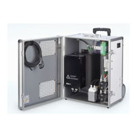
Portable Gas Conditioning Unit
Brand: M&C
|
Category: Industrial Equipment
|
Size: 2 MB
Table of Contents
Advertisement
M&C PSS Series Instruction Manual (48 pages)
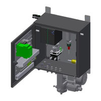
Gas Conditioning Unit
Brand: M&C
|
Category: Air Conditioner
|
Size: 3 MB
Table of Contents
M&C PSS Series Instruction Manual (43 pages)
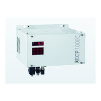
Gas Conditioning Unit
Brand: M&C
|
Category: Industrial Equipment
|
Size: 1 MB
Table of Contents
Advertisement
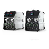
M&C PSS Series Instruction Manual (33 pages)
Portable Gas Conditioning Unit
Brand: M&C
|
Category: Industrial Equipment
|
Size: 0 MB
Table of Contents

M&C PSS Series Instruction Manual (26 pages)
Gas Conditioning Unit
Brand: M&C
|
Category: Test Equipment
|
Size: 0 MB
Table of Contents
M&C PSS Series Instruction Manual (25 pages)
Portable Gas Conditioning Unit
Brand: M&C
|
Category: Analytical Instruments
|
Size: 0 MB
Table of Contents
Advertisement