M&C PSS Series Instruction Manual
Gas conditioning unit
Hide thumbs
Also See for PSS Series:
- Instruction manual (48 pages) ,
- Instruction manual (43 pages) ,
- Instruction manual (26 pages)

Related Manuals for M&C PSS Series


Summary of Contents for M&C PSS Series
- Page 1 Gas Conditioning Unit Series PSS ® SS-M05 for Marine Application Instruction Manual Version 1.01.00...
- Page 2 Dear customer, Thank you for buying our product. In this manual you will find all necessary information about this M&C product. The information in the manual is fast and easy to find, so you can start using your M&C product right after you have read the manual.
-
Page 3: Table Of Contents
List of Contents General Information ........................5 Declaration of Conformity ......................5 Safety Instructions ........................6 Intended Use ........................6 Qualified Personnel ......................6 Electrical Voltage ......................... 7 Warranty ............................ 8 Used Terms and Signal Indications ..................9 Introduction ..........................11 Serial Numbers ........................ - Page 4 List of Figures Figure 1 Gas flow diagram ......................12 Figure 2 Dimensions and design SS-M05 ..................15 Figure 3 Sample gas line connection .................... 18 Figure 4 Media connections 2 to 5 ....................20 Figure 5 Media connection for downstream analyzer ..............21 Figure 6 Cable glands ........................
-
Page 5: General Information
HEAD OFFICE M&C TechGroup Germany GmbH Rehhecke 79 40885 Ratingen Germany Telephone: 02102 / 935 – 0 Fax: 02102 / 935 – 111 E - mail: info@mc-techgroup.com www.mc-techgroup.com GENERAL INFORMATION The product described in this instruction manual has been built and tested in our production facility. All M&C products are packed to be shipped safely. -
Page 6: Safety Instructions
SAFETY INSTRUCTIONS Follow these safety directions and instructions regarding installation, commissioning and operation of the equipment: Read this manual before commissioning and operating the product. Make sure to follow all safety instructions. Installation and commissioning of electrical devices must be carried out only by qualified skilled personnel in compliance with the current regulations. -
Page 7: Electrical Voltage
Qualified personnel in the sense of the safety instructions in this instruction manual or on the product itself are persons who as project personnel are familiar with the safety concepts of the gas treatment device, or • • as operating personnel are trained in the use of gas treatment devices and are familiar with the contents of this manual relating to its operation, or as maintenance and/or service personnel have been trained in the repair of such devices of •... -
Page 8: Warranty
WARRANTY In case of a device failure, please contact immediately M&C or your M&C authorized distributor. We have a warranty period of 12 months from the delivery date. The warranty covers only appropriately used products and does not cover the consumable parts. Please find the complete warranty conditions in our terms and conditions. -
Page 9: Used Terms And Signal Indications
USED TERMS AND SIGNAL INDICATIONS The ‘Danger’ warning sign indicates that death, serious injury and/or significant material damage will be the consequence, if the appropriate precautions should not be taken. D a n g e r The ‘Warning’ warning sign indicates that death, serious injury or damage to property may occur if the relevant precautionary measures are not observed. - Page 10 Wear safety glasses! Protect your eyes while working with chemicals or sharpe objects. Wear safety glasses to avoid getting something in your eyes. Wear protective clothes! Working with chemicals, sharpe objects or extremly high temperatures requires wearing protective clothes. SS-M05_Marine | 1.01.00 www.mc-techgroup.com...
-
Page 11: Introduction
INTRODUCTION The gas treatment device is used for gas preparation of continuous measurement of emissions in Marine applications. The system consists of a stainless steel housing which accommodates the main components such as cooler, peristaltic pump, bellow valve pump, flowmeter with sensor and components for auto calibration of the analyzer. -
Page 12: Application
APPLICATION The gas conditioning device is ideally suited for both intermittent and continuous operation. The components of the system SS-M05 are intended for "standard use." We also provide a wide range of additional equipment and other components if special measurements are required. Figure 1 Gas flow diagram The sample gas is fed to the gas treatment device via a heated sample gas probe –E2 (supplied by... - Page 13 In case of liquid alarm at B1, pump -M1 is automatically switched off to protect the downstream analyzer. The error messages can be routed to the signalling terminal block. Detailed technical information on the built-in analysis device, as the sample gas cooler, the pumps etc. can be found in the attached operating instructions.
-
Page 14: Technical Data
TECHNICAL DATA Gas Conditioning Type SS-M05 Marine Part-No 03G6000 Classification GL (Germanischer LLoyd ) DNVGL-CG-0339 Standortklassen Temperature Moisture Vibration Housing Sample outlet dew point Range of adjustment: +2 to +15 °C [35.6 to 59 °F], factory setting: +5 °C [41 °F] Sample outlet dew point stability At const. -
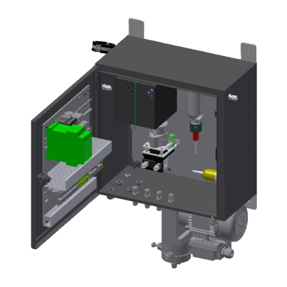
Page 15: Dimensions
DIMENSIONS Dimensions in mm Gas cooler Solenoid valve for test gas feeding Sample gas pump MP-F 05 with needle valve Filter FP-2T-D Filter porosity 2 μm with integrated liquid alarm sensor LA Flow meter FM40 with flow monitoring FA-20mo ... -
Page 16: Description
DESCRIPTION All components of the gas conditioning system are either housed in a compact stainless steel housing or attached to it. The sample gas line is connected directly to the heat exchanger inlet of the sample gas cooler. The sample gas cooler cools the sample gas down to 5 °C [41 °F]. The heat exchanger is placed inside a heat-insulated cooling block. -
Page 17: Receipt Of Goods And Storage
RECEIPT OF GOODS AND STORAGE Heavy device! Risk of injury when handling heavy equipment. Do not lift, move or carry the device without help. A second person is Warning required to lift, move or carry the device. The gas conditioning device SS-M05 is a completely pre-installed unit. •... -
Page 18: Connecting The Sample Gas Line
Do not use the gas conditioning device at temperatures other than those specified. This avoids false alarms and ensures the operational safety of the gas conditioning system and the additionally connected analyzer. Downstream analysers and the unheated Teflon tubing must always be operated at temperatures well above the specified gas output dew point of +5 °C. - Page 19 Connect the heated sample gas line as follows: 1. Connect heated sample line –E2 to the inlet of the heat exchanger “A1”. At least 60 mm unheated tube should be at the end of the heated line. 2. Check tightness! 3.
-
Page 20: Connecting The Tubing
CONNECTING THE TUBING Do not confuse tubing connections; connections are marked accordingly. Note After connecting all tubing, check for leaks. 12.1 MEDIA CONNECTIONS The condensate outlet of the heat exchanger is connected to the media connection 2. Media connection 3 is the condensate outlet of the peristaltic pump. The media connection 3 must be lead to a condensate collecting container supplied by the customer. -
Page 21: Figure 5 Media Connection For Downstream Analyzer
Media connection for downstream analyzer Figure 5 Media connection for downstream analyzer The sample gas inlet is a Ø 6 mm tube. All tubing connections are equipped with 4/6mm sealing ring threaded hose couplings made of PVDF, for gas input temperatures of up to a maximum of 80 °C. If heated sample lines are used, whereby the gas input temperatures are increased up to a maximum of 180 °C, additional bulkhead unions made of stainless steel are necessary. -
Page 22: Electrical Connections
Wear protective gloves and protective glasses! Wear proper protective clothing! 12.2 ELECTRICAL CONNECTIONS Wrong supply voltage can damage the equipment. When connecting the equipment, make sure the supply voltage is identical with the information provided on the model type plate! Warning For the erection of power installations with rated voltages up to 1000V, the requirements of VDE 0100 and relevant standards and... -
Page 23: Electrical Installation
Cable glands Cable gland for sample gas pump Figure 6 Cable glands 12.3 ELECTRICAL INSTALLATION Carry out the electrical installation (the electrical fuses of the gas conditioning device must be switched off): 1. Connect the mains power supply (see –X1 in circuit diagram). a. -
Page 24: Starting
Figure 7 Terminals X1, X2, X3 STARTING Observe the plant-specific and process-specific safety measures before commissioning. Before connecting the mains voltage, the circuit breakers must be set to OFF. Note The following steps must be carried out before initial commissioning: 1. -
Page 25: Function Sequence And Led Function Display
13.1 FUNCTION SEQUENCE AND LED FUNCTION DISPLAY Detailed technical information about the sample gas cooler can be found in the ECP1150M operating manual. Note The three indicator LED’s display the actual operating status during the commissioning of the gas cooler. The upper red LED indicates that the temperature set by the ECP 1150M electronic control unit has been exceeded or has not been reached. -
Page 26: Closing Down
CLOSING DOWN The area in which the equipment is situated when not in use must be kept free of frost at all times. Note There are no special regulations to be observed if the gas conditioning system is to be closed down for a short period of time. -
Page 27: Maintenance
MAINTENANCE Maintenance intervals in Maintenance work months Option Check, clean or replace of the filter -FI1 Check and replace of the filter -FI2 Check for condensate in the lines after the gas cooler Check the temperature of the Peltier sample gas cooler Replace hoses of the peristaltic pump Replace valve plate and O-rings of the bellow... -
Page 28: Maintenance Cooler
15.1 MAINTENANCE COOLER Detailed technical information about the sample gas cooler can be found in the ECP1150M operating manual. Note Observe the plant- and process-specific safety measures before carrying out maintenance work! Dangerous voltage. Disconnect the mains plug before opening the Warning cooler housing! The ECP 1150M coolers do not require special maintenance intervals. -
Page 29: Maintenance Peristaltic Pump
4. Lightly push the heat exchangers with rotation back into the push-in opening of the cooling block and press to the upper block; 5. Remove the adhesive tape and any surplus thermal conductivity paste; 6. Reconnect the tubing. Do not confuse tubing. The upper heat exchanger connection is the inlet, the side heat exchanger connection is the outlet and the lower heat exchanger connection is the condensate outlet. -
Page 30: Changing The Pump Tubing
Peristaltic pump is under pressure! Do not open housing! A peristaltic pump might be part of a system, which is under pressure. Check pressure before opening peristaltic pump, and adjust pressure to atmosheric pressure. Flexible tube, conveying belt, contact pulleys and contact springs are the only parts of the pump subject to wear. -
Page 31: Changing Contact Pulleys And Springs
7. Put the conveying belt with the new tubing into the dovetail guide of the pump body; 8. Press conveying belt at the recessed grips and simultaneously turn the S-bolt anticlockwise until it snaps; Switch on pump. Figure 9 Different pump tube sizes 15.2.2 CHANGING CONTACT PULLEYS AND SPRINGS... -
Page 32: Reassembly Of The Driver
5. The removal of the springs .4 pcs.) away from the driver is easily possible without the aid of any tools. For this take spring out of the groove near to the shaft bore. 6. Dismount roller axes and change contact pulleys. Take care that axes are not worn out by the springs and have damaged the dent at the axes front end. -
Page 33: Cleaning The Pump Head
15.2.4 CLEANING THE PUMP HEAD When changing flexible tube or other parts, inspect all parts for dirt before assembling the pump • head and clean them if necessary. • We recommend to clean the parts with a dry cloth. Solvent should not be used, because it can damage the plastics and synthetic rubber parts. -
Page 34: Maintenance Sample Gas Pump
15.3 MAINTENANCE SAMPLE GAS PUMP Detailed technical information on the sample gas pump can be found in the MP-F05 instruction manual. The instruction manual can be found at www.mc-techgroup.com Note It is necessary to schedule maintenance work at least twice a year. The intervals between servicing are dependent on the process and system conditions in your facility. -
Page 35: Replacing The Valve Plates
Inspect the following Action pump components Pump Check pump for external damages and any leakage in regular intervals, at least two times per year. Capacitor Check the conditions of the adhesive covers of the vents in regular intervals. Replace capacitor with damaged adhesive cover. Bellows and valve plates Replace at least when performance of the pump decreases. -
Page 36: Figure 12 Sectional Drawing Mp-F
To replace the valve plates, proceed as follows: 1. Unscrew the crankcase cover. To do this, loosen the 3 hexagon socket screws F (3 mm spanner). 2. Loosen the four hex socket screws G (3 mm spanner). 3. Remove pressure ring H. 4. -
Page 37: Replacing The Bellows
5. Then tighten the four hexagon socket screws alternately in the same sequence with a torque to a value of 5 Nm [≈ 3.69 ft/lbs]. 6. Screw the crankcase cover back on again. Tighten the three hexagon socket screws F (wrench 3 mm) by hand. -
Page 38: Cleaning Instructions
3. Install the upper pump head A and then the pressure ring H again. Align both so that the screws fit into the threads in the housing. 4. Check that the bellows are seated correctly. The bellows must be attached to the connecting rod. 5. -
Page 39: Trouble Shooting
TROUBLE SHOOTING Error messages: • Condensate alarm – B1 terminal -X2: 1/2 • Flow monitoring alarm – B2 terminal -X2: 4/5 The error messages can be retrieved potential-free at the terminal rail -X2. Maximum contact load 250 V AC/DC, AC=500 VA, DC=45 W, 2 A Note that the liquid alarm and the Peltier cooler alarm stops the bellow pump with needle valve! N o t e... -
Page 40: Disposal
Indication Problem Possible Cause Check/Solution Clean clogged line or replace; Gas flows? Cooler is overloaded momentarily due to excessive amount of condensate; WARNING! Aggressive condensate! Use Optional liquid alarm personal protective equipment! Check tubing sensor: for condensate removal; Alarm LED on Sensor turns the LA electro-... -
Page 41: Spare Parts List
SPARE PARTS LIST The replacement interval for spare parts and consumables depends on the specific operating condition of the probe. The quantities recommended in the following table are based on experience. Your replacement intervals will be based on your operating conditions. Portable Sampling System Versions SS-M05 (C) consumable parts, (R) recommended spare parts, (S) spare parts recommended quantity... - Page 42 Portable Sampling System Versions SS-M05 (C) consumable parts, (R) recommended spare parts, (S) spare parts recommended quantity SS-M05 being in operation [years] C/R/S 94F0015 Flowmeter glass for FM40 range 25-250 l/h air 94F0020 Flowmeter glass for FM40 range 50-500 l/h air 90A0018 Viton O-ring 9 for flowmeter glass FM40 Diverse:...
-
Page 43: Appendix
APPENDIX Wiring diagram part 1 • • Wiring diagram part 2 Type Approval Certificate DNV GL • Further product information is available on our home page: www.mc-techgroup.com Instruction manual electric gas cooler ECP1150M • • Universal-Filters FP, FT, FPK, FS, FSS : 7.1 Data sheet Instruction manual bellows pump with needle valve MP-F05... -
Page 44: Figure 13 Wiring Diagram Part 1
Figure 13 Wiring diagram part 1 SS-M05_Marine | 1.01.00 www.mc-techgroup.com... -
Page 45: Figure 14 Wiring Diagram Part 2
Figure 14 Wiring diagram part 2 www.mc-techgroup.com SS-M05_Marine | 1.01.00... - Page 46 SS-M05_Marine | 1.01.00 www.mc-techgroup.com...
- Page 47 www.mc-techgroup.com SS-M05_Marine | 1.01.00...
- Page 48 SS-M05_Marine | 1.01.00 www.mc-techgroup.com...
Need help?
Do you have a question about the PSS Series and is the answer not in the manual?
Questions and answers