M&C PSS Series Instruction Manual
Gas conditioning unit
Hide thumbs
Also See for PSS Series:
- Instruction manual (48 pages) ,
- Instruction manual (25 pages) ,
- Instruction manual (48 pages)

Related Manuals for M&C PSS Series


Summary of Contents for M&C PSS Series
- Page 1 Gas Conditioning Unit Series PSS ® SS5C, SS5C/2, SS5C/3 Instruction Manual Version 1.00.00...
- Page 2 Dear customer, Thank you for buying our product. In this manual you will find all necessary information about this M&C product. The information in the manual is fast and easy to find, so you can start using your M&C product right after you have read the manual.
-
Page 3: Table Of Contents
List of Contents General information............................5 Declaration of conformity ..........................5 Safety instructions ............................6 Warranty ................................. 6 Used terms and signal indications......................7 Type plate ..........................................8 Introduction ..............................9 Function of the M&C Jet-Stream heat exchanger ..................9 Application .............................. - Page 4 List of Figures Figure 1 Type plate ........................................8 Figure 2 Diagram of the heat exchanger function............................ 9 Figure 3 Gas flow diagram of the SS5C and SS5C/3 ..........................10 Figure 4 Gas flow diagram of the SS5C/2 ..............................11 Figure 5 Dimensions and design: SS5C and SS5C/3 ..........................
-
Page 5: General Information
HEAD OFFICE M&C TechGroup Germany GmbH Rehhecke 79 40885 Ratingen Germany Telephone: 02102 / 935 – 0 Fax: 02102 / 935 – 111 E - mail: info@mc-techgroup.com www.mc-techgroup.com GENERAL INFORMATION The product described in this instruction manual has been built and tested in our production facility. All M&C products are packed to be shipped safely. -
Page 6: Safety Instructions
SAFETY INSTRUCTIONS Follow these basic safety procedures when mounting, starting up or operating this equipment: Read this operating manual before starting up and use of the equipment. The information and warnings given in this operating manual must be heeded. Any work on electrical equipment is only to be carried out by trained specialists as per the regulations currently in force. -
Page 7: Used Terms And Signal Indications
USED TERMS AND SIGNAL INDICATIONS This means that death, severe physical injuries and/or important material damages will occur in case the respective safety measures are not fulfilled. Danger This means that death, severe physical injuries and/or important material damages may occur in case the respective safety measures are not fulfilled. Warning This means that minor physical injuries may occur in case the respective safety measures are not fulfilled. -
Page 8: Type Plate
Wear safety glasses! Protect your eyes while working with chemicals or sharp objects. Wear safety glasses to avoid getting something in your eyes. Wear protective clothes! Working with chemicals, sharp objects or extremely high temperatures requires wearing protective clothes. TYPE PLATE A type plate is located on the device. -
Page 9: Introduction
INTRODUCTION The unit, which is mounted on an aluminium plate, is a complete sample gas conditioning unit suitable for continuous use and can be easily integrated into analytical systems. This minimizes the effort for the procurement of individual components and small parts as well as the assembly of the individual parts. The compact design only requires a small amount of space. -
Page 10: Application
APPLICATION The gas conditioning units SS5C, SS5C/3 and SS5C/3 are ideally suited for both intermittent and continuous operation. The components of the systems SS5C, SS5C/3 and SS5C/3 are intended for "standard use." We also provide a wide range of additional equipment and other components if special measurements are required. Sample gas (4/6 mm) Condensate... -
Page 11: Figure 4 Gas Flow Diagram Of The Ss5C/2
Sample gas (4/6 mm) Condensate (2 x 4/6 mm) Gas cooler ECP2000C with two heat exchangers Fine filter FP-2T, filter element porosity 2 µm Sample gas pump N3 KPE, N5 KPE or N9 KPE Peristaltic pump SR25.2-W for continuous removal of condensate Figure 4 Gas flow diagram of the SS5C/2 www.mc-techgroup.com... -
Page 12: Technical Data
TECHNICAL DATA Gas Conditioning Type SS5C SS5C/2 SS5C/3 Part No. version 230 V/50 Hz 03G7000 03G7050 03G7500 Part No. version 115 V/60 Hz 03G7000a 03G7050a 03G7500a Sample gas outlet dew point Range of adjustment: 2 to 15 °C [35.6 to 59 °F], factory setting: +5 °C [41 °F] Sample gas outlet dew point stability At const. - Page 13 Optionen Artikel-Nr. mA output cooler 1 x mA output including plug and socket, mounting and 01K9200 calibration per channel included Liquid alarm sensor Liquid alarm sensor Type LA1S, LA sensor with cable break 01G9260 detection Temperature controller Range of control: 0 to 200 °C [32 to 392 °F] 01G9055(a) for a max.
-
Page 14: Description
DESCRIPTION Terminal mounting rail Cooler, sample gas OUT Cooler, sample gas IN Fine filter FP-2T Diaphragm sample gas pump Peristaltic pump SR25.2-W, condensate OUT (all connections DN 4/6) Figure 5 Dimensions and design: SS5C and SS5C/3 SS5C, SS5C/2, SS5C/3 | 1.00.00 www.mc-techgroup.com... -
Page 15: Figure 6 Dimensions And Design: Ss5C/2
Terminal mounting rail Cooler, sample gas OUT Cooler, sample gas IN Fine filter FP-2T Diaphragm sample gas pump Peristaltic pump SR25.2-W, condensate OUT (all connections DN 4/6) Figure 6 Dimensions and design: SS5C/2 All components of the gas conditioning system are mounted on an aluminium plate and are freely accessible. The gas cooler and an appropriate diaphragm gas pump are installed depending on the required maximum gas flow (for operating instructions for individual components, see Appendix). - Page 16 All gas coolers are equipped with a Duran glass heat exchanger. Heat exchangers of PVDF or stainless steel are also available. The pre-filter FP-2T (2 µm filter element porosity) installed upstream of the sample gas pump ensures the necessary separation of solids. To protect downstream analyzers, the overtemperature alarm contact (+8 °C [46.4 °F]) of the cooler automatically switches the sample gas pump on and off.
-
Page 17: Operating Instructions
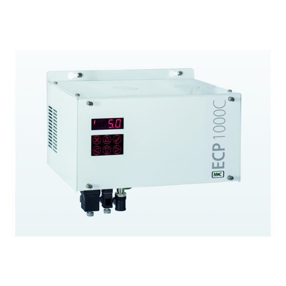
OPERATING INSTRUCTIONS The display and control panel of the ECPX000C are clearly visible on the front panel of the built-in cooler. The functions described here are excerpts from the operating instructions of the ECPX000C series. For the complete documentation, read the ECPX000C instruction manual. It can be downloaded from the M&C homepage. The complete instruction manual of the ECPX000C can be found at www.mc- techgroup.com. -
Page 18: Pin Entry
Tap on the -key, to go back to the cooling temperature. Note The cooling temperature is shown in the display as follows: The cooler temperature is shown on the display. The ambient temperature is indicated by a "°" sign on the left side of the displayed temperature. -
Page 19: Set Point Entry
After confirmation, immediately the display for the set point entry is shown. Press and hold the -key longer to access the parameter setting area. The PIN is valid for 15 minutes. If you exceed this time, the display field reappears with "0000" when you press and hold the -key. -
Page 20: Parameter Setting
PARAMETER SETTING If you tap the -key after entering the PIN (see chapter “11.2 PIN Entry”), the set point for the cooler temperature appears first. If the -key is pressed and held for a short moment, the display changes to code entry. Here you can enter the codes that belong to the respective parameter settings. -
Page 21: Setting Temperature Alarm Limits
12.1 SETTING TEMPERATURE ALARM LIMITS You use the temperature alarm limits to determine when the alarm is triggered. HIGH dT and LOW dT are independently adjustable from dT = 2 to 8 °C [dT = 3.6 to 14.4 °F]. In the following figure, the upper temperature alarm limit is set at 8 °C [46.4 °F] and the lower one at 3 °C [37.4 °F]. -
Page 22: Fan Speed Setting
12.2 FAN SPEED SETTING The ECPX000C is equipped with a large cooling fin block which is forced-ventilated by a fan. The minimum speed of the fan can be changed without affecting the final performance of the cooler. To change the fan speed setting: 1. -
Page 23: Option: Ma Output For The Temperature Measurement Inside The Cooling Block
OPTION: MA OUTPUT FOR THE TEMPERATURE MEASUREMENT INSIDE THE COOLING BLOCK The mA outputs built-in by M&C are factory calibrated and set to the range "4-20 mA". Later purchased mA outputs must be calibrated. 13.1 MA OUTPUT RANGE SELECTION The optional mA output can be changed from 4-20 mA to 0-20 mA. To select the mA range, proceed as follows: 1. - Page 24 If a calibration error occurs and the mA output has been calibrated, the limiting values also change! Note To calibrate an mA output, proceed as follows: 1. Enter the PIN (see chapter “11.2 PIN Entry”). 2. Tap and hold the -key for a short moment.
-
Page 25: Option: Liquid Alarm Sensor (La) Type La1S
OPTION: LIQUID ALARM SENSOR (LA) TYPE LA1S M&C installs the liquid alarm sensors type LA1S with cable break detection. They are factory calibrated to tap water and activated with cable break detection. Later purchased liquid alarm sensors must be activated and calibrated. 14.1 ACTIVATING THE LA A retrofit liquid alarm sensor LA1S must be activated. -
Page 26: La Sensitivity Adjustment
14.2 LA SENSITIVITY ADJUSTMENT The sensitivity can be changed by following these steps: 1. Enter the PIN (see chapter “11.2 PIN Entry”). 2. Tap and hold the -key for a short moment. 3. The display shows the code entry. Enter the code "011" to change the sensitivity of the liquid sensor. The default value is 2 and can be changed from 1 to 7. -
Page 27: Receipt Of Goods And Storage
14.3 LA CALIBRATION The liquid alarm sensors LA1S with cable break detection installed by M&C are factory activated and calibrated. If required, the basic accuracy of the liquid alarm sensors can be optimized by recalibration. Later-installed liquid sensors must be activated and calibrated. Make sure that the LA is activated. -
Page 28: Installation Instructions
INSTALLATION INSTRUCTIONS The equipment is to be used in a vertical position only. The perfect functioning of the separation and drainage procedures will only be guaranteed if the equipment is used in a vertical position. Note The gas conditioning system should be installed in an area well away from any heat emitting sources in order to prevent damage caused by an accumulation of heat. -
Page 29: Supply Connections
SUPPLY CONNECTIONS 17.1 HOSE CONNECTIONS Do not switch tube connections; connections are marked accordingly. After all lines have been connected, the tightness must be checked. Note All tube connections are equipped with 4/6 mm clamping ring tube fittings made of polyvinylidenfluoride (PVDF) for gas inlet temperatures of up to a maximum of 80 °C [176 °F] (see chapter “9 Technical data”). -
Page 30: Electrical Connections
17.2 ELECTRICAL CONNECTIONS Wrong supply voltage can damage the equipment. When connecting the equipment, make sure that the supply voltage is identical with the Warning information provided on the model type plate! For the erection of power installations with rated voltages up to 1000V, the requirements of VDE 0100 and relevant standards and specifications must be observed! Note... -
Page 31: Figure 12 Electrical Connections For 115 V
Figure 12 Electrical connections for 115 V Option “temperature controller for heated sample lines”: For the electrical supply and control of a heated sample line with PT-100 a 7-pin plug at the side of the unit is available. The connection power is max. 6 A, 1380 W for the 230 V version or 6 A, 690 W for the 115 V-version. The maximum length of the heated sample line which can be used is calculated as follows: Max. - Page 32 Option “heated sample line”: For the electrical supply of a heated line with PT-100 sensor a 7-pin connector is available. For the electrical supply of other heated components (e.g., heated sample gas probe or heated filter) a 4-pole round plug connector is available at the heated lines Part No 01B4050 or 01B4040. The maximum connected load is 6 A, 1380 W for the 230 V sample gas conditioning unit and 6 A, 690 W for the 115 V version.
-
Page 33: Commisioning
COMMISIONING Observe the facility and process-specific safety measures before commissioning. Carry out the following steps before initial commissioning: 1. Connect the cable to the terminal mounting rail. 2. Connect the heated sample line (optionally). Check the temperature at the temperature controller when operating the Warning sample gas conditioning unit with a heated sample gas line 3. -
Page 34: Closing Down
CLOSING DOWN The area where the gas conditioning unit is placed must remain frost-free even when the unit is switched off. Note No special measures are to be taken in the event of short-term shutdowns of the gas conditioning unit. In the case of long-term shutdowns, for example after a completed series of measurements, it is recommended to purge the gas conditioning unit with fresh air or inert gas. -
Page 35: Maintenance
MAINTENANCE Observe the facility- and process-specific safety measures before carrying out maintenance work! Dangerous voltage! Warning It is necessary to take the equipment off the mains before any assembly, maintenance or repair work is carried out. The frequency of the maintenance work depends on the operational process and can therefore only be determined in each individual case. - Page 36 Alarm and Error Messages The cooler of the sampling system has several monitoring functions. If an alarm limit is exceeded or not reached or if an error occurs during operation, the corresponding messages are shown on the display. These messages are displayed cyclically and alternate with the current cooler temperatures.
-
Page 37: Trouble Shooting
TROUBLE SHOOTING The following table aims to point out possible operational problems and offer solutions to such problems (not applicable during the starting procedure). Problem Display Possible Causes Check/Solution No display No voltage Check supply voltage with model type plate; Check if mains voltage is applied to X1/2 and X1/3;... -
Page 38: Proper Disposal Of The Device
Problem Display Possible causes Check/Solution Pump tube defect Replace pump tube (see manual peristaltic pump SR25.2- Cooler and sample gas Peristaltic pump SR25.2- Check peristaltic pump (see manual peristaltic pump pump are W does not work SR25.2-W); Current cooler running; temperature(s) Condensate in the sample gas... -
Page 39: Spare Parts List
SPARE PARTS LIST Wear, tear and replacement part requirements depend on specific operating conditions. The recommended quantities are based on experience and are not binding. For spare parts of components which are not presented in the following list please see the specific instruction manuals or leaflets added in the appendix. - Page 40 Sampling System Versions SS5C, SS5C/2 and SS5C/3 (C) consumable parts, (R) recommended spare parts, (S) spare parts Recommended quantity during operation [years] C/R/S Option flowmeter FM40: 90A0015 Flowmeter glass for FM40 range 7 to 70 l/h air 94F0010 Flowmeter glass for FM40 range 15 to 150 l/h air 94F0015 Flowmeter glass for FM40...
-
Page 41: Appendix
APPENDIX • Circuit diagram SS5C, SS5C/2 and SS5C/3 More product documentation is available in our Internet catalogue: www.mc-techgroup.com • Instruction manual: Electric gas cooler ECPX000C • Data sheet: Universal-Filters FP, FT, FPK, FS, FSS • Instruction manual: Diaphragm pump Series N •... -
Page 42: Figure 13 Circuit Diagram Ss5C
Figure 13 Circuit diagram SS5C, SS5C/2 and SS5C/3 SS5C, SS5C/2, SS5C/3 | 1.00.00 www.mc-techgroup.com... - Page 43 Table of Parameter Codes Description: Default: Range: Note: Software version Brightness setting of 0 - 9 Brightest display setting is 9 display LA on/off switching 0,1,2 0=off; 1= without cable break detection; 2= with cable break detection Sensitivity LA The higher the value is, the sooner the alarm is triggered. HIGH dT 2 - 8 [°C] Differential temperature between set point and upper...
Need help?
Do you have a question about the PSS Series and is the answer not in the manual?
Questions and answers