M&C PSS Series Instruction Manual
Portable gas conditioning unit
Hide thumbs
Also See for PSS Series:
- Instruction manual (48 pages) ,
- Instruction manual (26 pages) ,
- Instruction manual (33 pages)

Related Manuals for M&C PSS Series


Summary of Contents for M&C PSS Series
- Page 1 ® Portable Gas Conditioning Unit Series PSS PSS-10/1 Instruction Manual Version 1.00.02...
- Page 2 Dear customer, Thank you for buying our product. In this manual you will find all necessary information about this M&C product. The information in the manual is fast and easy to find, so you can start using your M&C product right after you have read the manual.
-
Page 3: Table Of Contents
Content General information ............................4 Declaration of conformity ..........................4 Safety instructions ............................5 Warranty ................................5 Used terms and signal indications ....................... 6 Introduction ..............................8 Application ................................ 8 Technical data ..............................9 Description ..............................10 Receipt of goods and storage ........................12 Installation instructions .......................... -
Page 4: General Information
HEAD OFFICE M&C TechGroup Germany GmbH Rehhecke 79 40885 Ratingen Germany Telephone: 02102 / 935 – 0 Fax: 02102 / 935 – 111 E - mail: info@mc-techgroup.com www.mc-techgroup.com GENERAL INFORMATION The product described in this instruction manual has been built and tested in our production facility. All M&C products are packed to be shipped safely. -
Page 5: Safety Instructions
SAFETY INSTRUCTIONS Please take care of the following basic safety procedures when mounting, starting up or operating this equipment: Read this operating manual before starting up and use of the equipment. The information and warnings given in this operating manual must be heeded. Any work on electrical equipment is only to be carried out by trained specialists as per the regulations currently in force. -
Page 6: Used Terms And Signal Indications
USED TERMS AND SIGNAL INDICATIONS This means that death, severe physical injuries and/or important material damages will occur in case the respective safety measures are not fulfilled. D A N G E R ! This means that death, severe physical injuries and/or important material damages may occur in case the respective safety measures are not fulfilled. - Page 7 Wear safety glasses! Protect your eyes while working with chemicals or sharp objects. Wear safety glasses to avoid getting something in your eyes. Wear protective clothes! Working with chemicals, sharp objects or extremely high temperatures requires wearing protective clothes. www.mc-techgroup.com PSS-10 | 1.00.02...
-
Page 8: Introduction
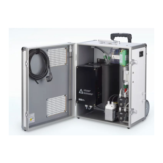
INTRODUCTION The portable gas conditioning and sampling system PSS-10/1 has been especially designed so that precise gas analyses can be carried out in any place and at any time. The entire gas conditioning system is housed in a compact and robust aluminium framed case which ensures that the components can be removed easily, and gas analysis carried out quickly, safely and with a minimum amount of maintenance. -
Page 9: Technical Data
TECHNICAL DATA Gas conditioning unit Version PSS-10/1 Sample outlet dew point Range of adjustment: +2 to +15 °C [35.6 to 59 °F], factory setting: +5 °C [41 °F] Dew point stability At const. conditions: < ±0.1°C [±0.18 °F] Sample inlet temperature **Max. -
Page 10: Description
DESCRIPTION Sample GL 18 Power Sample Condensate GL 25 Figure 2 Design of the portable conditioning and sampling system PSS-10/1 All the components of the gas conditioning system can be easily removed from the portable case. The door of the case can be opened by moving the toggle-type fasteners ... - Page 11 Options The gas conditioning and sampling system PSS-10/1 consists of standard one gas-measuring outlet terminal. An additional flow meter (DK800R), with needle valve, can be fitted to this terminal, whereby the adjustment of the terminals is carried out in accordance with the specified volume flow rate (see 3.). In order to protect additionally connected analysers against fluid irruption, and increase the operational safety of the entire system, we recommend that a fluid alarm sensor LA 1S be installed.
-
Page 12: Receipt Of Goods And Storage
RECEIPT OF GOODS AND STORAGE Heavy device! Risk of injury when handling heavy equipment. C A U T I O N ! Do not lift, move or carry the device without help. A second person is required to lift, move or carry the device. The portable gas conditioning and sampling system PSS-10/1 is a completely pre-fitted unit. -
Page 13: Installation Instructions
INSTALLATION INSTRUCTIONS Heavy device! Risk of injury when handling heavy equipment. C A U T I O N ! Do not lift, move or carry the device without help. A second person is required to lift, move or carry the device. When in use, the gas conditioning system case should be placed in an area well away from any heat emitting sources in order to prevent damage caused by an accumulation of heat. -
Page 14: Supply Connections
SUPPLY CONNECTIONS 12.1 TUBE CONNECTIONS Do not switch tube connections; connections are marked accordingly. After all lines have been connected, the tightness must be checked. N O T E ! Figure 3 shows the possible medium connections. These are located in the right-hand side of the gas conditioning case at the rear in a specially immersed assembly frame. - Page 15 Install the sample gas tubes and the condensate tube as follows: 1. Remove the union nut from the clamping ring tube fittings by turning it anti-clockwise. The nut should be removed from the thread with great care so as to ensure that the loose sealing ring in the nut is not lost. 2.
-
Page 16: Electrical Connections
12.2 ELECTRICAL CONNECTIONS Wrong supply voltage can damage the equipment. When connecting the equipment, make sure that the supply voltage is identical with the W A R N I N G ! information provided on the model type plate! For the erection of power installations with rated voltages up to 1000V, the requirements of VDE 0100 and relevant standards and specifications must be observed! N O T E ! -
Page 17: Commisioning
COMMISIONING Observe the facility and process-specific safety measures before commissioning. Carry out the following steps before initial commissioning: 1. Place the cold appliance plug, which is delivered with the mains supply cable, into the cold appliance plug socket. 2. Connect the heated sample line (option). Check the temperature at the temperature controller when operating the W A R N I N G ! sample gas conditioning unit with a heated sample gas line. -
Page 18: Closing Down
CLOSING DOWN The area where the gas conditioning unit is placed must remain frost- free even when the unit is switched off. N O T E ! No special measures are to be taken in the event of short-term shutdowns of the gas conditioning system. In the case of long-term shutdowns, for example after a completed series of measurements, it is recommended to purge the gas conditioning system with fresh air or inert gas. -
Page 19: Maintenance
MAINTENANCE Before the maintenance work is carried out, it is necessary that the specific safety procedures pertaining to the system and operational process be observed! Dangerous voltage! W A R N I N G ! It is necessary to take the equipment off the mains before any assembly, maintenance or repair work is carried out. -
Page 20: Trouble Shooting
TROUBLE SHOOTING The following table aims to point out possible operational problems and offer solutions to such problems (not applicable during the starting procedure). Indication Problem Possible Cause Check/Solution Interruption of No voltage; Check supply voltage with model type plate; gas flow;... -
Page 21: Proper Disposal Of The Device
Indication Problem Possible Cause Check/Solution Cooler and gas Middle LED on Pre-filter clogged up; Remove filter from condensate lead; pump in cooler is green; Pump delivering? operation; Change filter; condensate in Pump hose faulty; Pump not delivering? sample gas lead; Change pump hose (see manual SR25.1);... -
Page 22: Spare Parts List
SPARE PARTS LIST Wear, tear and replacement part requirements depend on specific operating conditions. The recommended quantities are based on experience and are not binding. For spare parts of components which are not presented in the following list please see the specific instruction manuals or leaflets mentioned in the appendix. -
Page 23: Appendix
Portable Sampling System Version PSS-10/1 (C) consumable parts, (R) recommended spare parts, (S) spare parts recommended quantity PSS-10/1 being in operation [years] C/R/S Diverse: 90G0006 Pre-filter PF 2 for condensate pump SR25.1 90G0030 Fine fuse 6.3 A slow-acting, 5 x 20 mm for PSS... 90G0020 Fine fuse 10 A slow-acting, 5 x 20 mm for PSS... -
Page 24: Figure 4 Connecting Heated Sample Line With Special Adapter (Option)
C o n n e c t i n g t h e h e a t e d s a m p l e l i n e w i t h s p e c i a l a d a p t e r Sample gas IN Heated sample line Union nut 10 mm Øi... -
Page 25: Figure 5 Circuit Diagram Pss-10/1, Shown Here: Circuit Diagram For 230 V
Figure 5 Circuit diagram PSS-10/1, shown here: circuit diagram for 230 V www.mc-techgroup.com PSS-10 | 1.00.02...
Need help?
Do you have a question about the PSS Series and is the answer not in the manual?
Questions and answers