Sign In
Upload
Manuals
Brands
Labconco Manuals
Laboratory Equipment
Logic+ A2
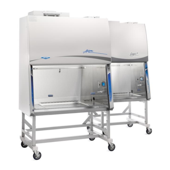
Labconco Logic+ A2 Biosafety Cabinet Manuals
Manuals and User Guides for Labconco Logic+ A2 Biosafety Cabinet. We have
2
Labconco Logic+ A2 Biosafety Cabinet manuals available for free PDF download: Technical Manual, User Manual
Labconco Logic+ A2 Technical Manual (201 pages)
Biosafety Cabinets, Procedure Stations
Brand:
Labconco
| Category:
Laboratory Equipment
| Size: 9 MB
Table of Contents
Table of Contents
4
1: Introduction
11
Contacting Labconco
11
About this Manual
12
Theory of Operation
12
Type A2
12
Type B2
13
Type C1 - a Mode
13
Type C1 - B Mode
14
2: Safety Precautions
15
Typographical Conventions
15
General Safety Precautions
17
Safety Precautions for this Product
19
3: Catalog Number Configurator
21
4: Serial Tag
22
Serial Tag Location
22
Serial Tag Information
23
Primary Serial Tag
23
Secondary Serial Tag
23
5: Factory Test Report
24
Test Report Location
24
Test Report Information
25
6: Additional Product Information
26
Data Plate Location
26
Data Plate Information
27
7: Exhaust System Connections
28
Exhaust Connection Best Practices
28
Air-Tight Damper
30
Exhaust System Requirements
31
Type A2 Models
31
Cell Logic+ Type A2 Models
32
Type B2 Models
32
Type C1 Models
33
8: Configuration
34
Current Configuration
34
Change Configuration
36
9: Calibration
40
Certifier Password
40
Adjusting Blower Speed
41
Adjusting the Internal Air Damper
43
Setting the Filter Life Gauge
45
Type A2 (8-Inch through 10-Inch Sash) and Type B2
45
Type A2 (12-Inch Sash) and Type C1
46
Airflow Sensor Calibration
47
Type A2 and Type C1
47
Type B2
48
Zero Point Calibration
50
Vacuum Start Switch Calibration (Type C1 Only)
51
10: Certification
53
Certifier Password
53
Type A2 HEPA Filter Leak Test Preparation
53
Theoretical Upstream Concentration
54
Upstream Concentration Sampling
54
Type A2 Supply HEPA Filter Leak Test
56
Acceptance Criteria
57
Type A2 Exhaust HEPA Filter Leak Test
58
Acceptance Criteria
59
Type B2 Supply HEPA Filter Leak Test Preparation
60
Theoretical Upstream Concentration
60
Upstream Concentration Sampling
60
Type B2 Supply HEPA Filter Leak Test
62
Acceptance Criteria
63
Type B2 Exhaust HEPA Filter Leak Test Preparation
64
Theoretical Upstream Concentration
64
Type B2 Exhaust HEPA Filter Leak Test
65
Acceptance Criteria
65
Type C1 Supply HEPA Filter Leak Test Preparation
66
Theoretical Upstream Concentration
66
Upstream Concentration Sampling
66
Type C1 Supply HEPA Filter Leak Test
68
Acceptance Criteria
69
Type C1 Exhaust HEPA Filter Leak Test Preparation
70
Theoretical Upstream Concentration
70
Type C1 Exhaust HEPA Filter Leak Test
72
Acceptance Criteria
73
Downflow Velocity
74
Acceptance Criteria
75
Inflow Velocity
76
Primary Method
76
Acceptance Criteria
78
Secondary Method
79
Acceptance Criteria
83
Work Area Air Cleanliness Test (Optional)
84
Acceptance Criteria
84
Lighting Test (Optional)
85
Acceptance Criteria
85
Noise Test (Optional)
86
Acceptance Criteria
86
Vibration Test (Optional)
86
UV Light Intensity Test (Optional)
87
Acceptance Criteria
87
Ground Fault Circuit Interrupter (GFCI) Test
88
Acceptance Criteria
88
11: Quickcharts
89
Quickchart - Type A2 3-Ft & 4-Ft
90
Quickchart - Type A2 5-Ft & 6-Ft
91
Type A2 Footnotes
92
Quickchart - Type B2
93
Type B2 Footnotes
94
Quickchart - Type C1
95
Type C1 Footnotes
96
12: Advanced Service Procedures
97
Tools
97
Required
97
Optional
97
Removal of External Dress Panels
98
Dress Panel
98
Side Panels
99
Front Sash
100
Sash Level Adjustment
100
Sash Sensor Adjustment or Replacement
101
HEPA Filter Replacement
104
Type A2 (8, 9, 10-Inch Sash)
104
Type A2 (12-Inch Sash)
107
Type B2
110
Type C1
114
Blower/Motor Replacement
117
Type A2 (8, 9, 10-Inch Sash) & B2
117
Type A2 (12-Inch Sash) & C1 Supply Blower/Motor
121
Type A2 (12-Inch Sash) & C1 Exhaust Blower/Motor
124
Changing the LED Lamps
129
LED Lamp Socket Cap Replacement
131
Changing the Optional UV Lamp
132
UV Lamp Socket Replacement
133
Type B2 Prefilter Replacement
134
Air-Tight Damper Adjustment
135
Preparing the Biosafety Cabinet for Gaseous Sterilization
136
Service Fixture Installation & Service Connection
137
13: Electrical Components
140
Electronics Module
140
Electronic Module Components
141
Resetting a Circuit Breaker
142
Power Supply Board
143
Display Board
144
Speaker
145
Blower Motor
146
Wiring Diagrams
148
100-115V
148
208-240V
149
14: Troubleshooting
150
Blower and Lights Not Working
150
Blower Only will Not Start
151
Lights Only will Not Illuminate
152
UV Light will Not Illuminate
153
Airflow Alert Activating
154
Filter Life Gauge Not at 100% When New
155
Contamination in the Work Area
156
15: Diagnostics
157
Sash Sensors
157
Keypad
158
Airflow Sensor (Optional)
159
Canopy (Optional)
160
16: Bms Data Output Connection
161
Connection Type
161
Data Output Format
162
Data Output Rate
162
Data Output String Definition
163
Data Output Software Requirements
164
17: Ventus Canopy Connection Kit
165
Kit Catalog Numbers
166
Installation Procedure
166
Exhaust Damper Installation Procedure
168
Canopy Switch Wiring Connection
168
Calibrate for Operation
169
18: Airflow Sensor Kit
171
Installation - Type A2 Without Ventus Canopy
171
Installation - Type A2 with Ventus Canopy
173
Connection to Electronics Module
175
Configuration (New Install Only)
176
Calibration
178
19: Uv Lamp Kit
181
Kit Catalog Numbers
181
Installation
181
Configuration
183
20: IV Bar Kit
185
Kit Catalog Numbers
185
Installation
185
21: Prefilter Kit
187
Kit Catalog Numbers (Type A2 and B2 Only)
187
Installation
187
Attach Prefilter(S) to Towel Catch - G4 Paper
188
Attach Prefilter(S) to Towel Catch - Aluminum Washable
189
22: en Alarm/Relay Contact Kit
190
Installation
190
Example 1 - Blower Relay Contact (Single Phase AC)
194
Example 2 - Blower Relay Contact (Three Phase AC)
195
23: Parts List
196
Type A2 Consumables
196
Type B2 Consumables
197
Type C1 Consumables
198
Advanced Service Components
199
Advertisement
Labconco Logic+ A2 User Manual (113 pages)
Biosafety Cabinets
Brand:
Labconco
| Category:
Laboratory Equipment
| Size: 7 MB
Table of Contents
Table of Contents
4
1: Introduction
9
About this Manual
9
Contents Included
9
2: before You Install
10
Location Requirements
10
Clearance Requirements
11
Electrical Requirements
11
Service Line Requirements
11
Exhaust Requirements
12
Air-Tight Damper
15
User-Supplied Microscope Requirements - Scope-Ready™ Package Only
15
User-Supplied Circulator Requirements - Temp-Zone™ Package Only
16
3: Safety Precautions
17
Typographical Conventions
17
General Safety Precautions
19
Safety Precautions for this Product
21
4: Installation
23
Unpacking
23
Electrical Connection
28
IEC Connector
28
Ethernet Connection
29
Connecting to Ethernet with a Standard Cell Logic Display
29
Connecting to Ethernet with a Remote Communications Board
30
Service Line Connection
31
Drain Valve Installation (Optional)
32
Exhaust Connection
33
Microscope Installation (Optional)
33
Circulator Installation (Optional)
35
Certification
37
5: Performance Features
38
Laminar Airflow
38
Directional Airflow
39
Cabinet Air Intake (Front Grille)
39
HEPA Filters
40
ULPA Filters
40
Motor/Blower
41
UV Lamp (Optional)
42
Scope-Ready TM Package (Optional)
42
Pure-Vu™ Seal
42
Stand-Still TM Isolation Platform
43
Temp-Zone TM Package (Optional)
43
6: Cell Logic Type A2 Operating System
44
Home Screen
44
Display Sleep Mode
45
Keypad
45
Navigating the Data Logs Menu
46
Navigating the Settings Menu
48
Configuration Submenu
48
Adjusting Sound
51
Selecting a Language
51
Setting the Clock
51
Selecting the Units of Measure
52
Activating the Security Lock
52
Setting the Data Acquisition Rate
52
Adjusting the Display
53
Utilizing Network Connection
53
Activating Email Alerts
54
Adjusting Maintenance Reminders
55
The Certification Submenu
56
Navigating the Help Menu
56
About
57
Software Update Via USB Thumbdrive
58
Software Update Via the Ethernet
58
Automatic Update Notification
58
Sensors
59
Diagnostics
60
Resources
60
Notifications
60
Timer Operation (Optional)
61
Airflow Alert
61
Resetting the Airflow Alert System
62
Alarms
62
Power Loss Alarm
63
Sash Height Alarm
63
Memory Failure
64
Blower Failure Alarm
64
Running Exhaust Alarm
65
7: Using Your Cell Logic Type A2
66
Feature Overview
66
System Reset Switch
67
Keypad
68
Sash Operation
69
Blower Operation
69
Light Operation
69
Outlet Operation
69
Vacu-Pass TM Cord & Cable Portal (Optional)
70
Working in the Cabinet
71
Planning
71
Cabinet Start-Up
71
Wipe down
72
Loading Materials and Equipment
72
Work Techniques
72
Final Purging
72
Unloading Materials and Equipment
72
Shutdown
73
8: Maintaining Your Cell Logic Type A2
74
Maintenance Safety Precautions
74
Recommended Maintenance Schedule
75
Service Operations
76
Resetting a Circuit Breaker
76
Cleaning Beneath Dished Work Surface (Temp-Zone™ Only)
77
Cleaning Beneath Dished Work Surface (Scope-Ready™ Only)
78
Front Grille Removal
79
Front Panel Removal
79
Changing the LED Lamps
80
Accessing Beneath the Exhaust Cover
82
Towel Catch Removal
83
Changing the Optional UV Lamp
85
Storage
85
9: Accessories
87
IV Bar
87
Ventus II Canopy
87
Electric Hydraulic Lift Base Stands (with Leveling Feet)
88
Electric Hydraulic Lift Base Stands (with Casters)
88
Solo TM Electric Hydraulic Lift Base Stands
89
Airflow Sensor
89
Telescoping Base Stands (Non-Welded)
90
Telescoping Base Stands (Welded)
90
Stand-Still TM Isolation Platform
91
Pure-VU TM Seals
91
10: Troubleshooting
92
Blower and Lights Not Working
92
Blower Only Will Not Start
93
Lights Only Will Not Illuminate
94
UV Light Will Not Illuminate
95
Airflow Alert Activating
96
Filter Life Gauge Not at 100% When New
97
Contamination in the Work Area
98
Appendix A: Parts List
99
Appendix B: Dimensions
101
Appendix C: Specifications
102
Power Data
102
Motor Specifications
102
Environmental Conditions
103
Appendix D: Quick Chart Reference
104
Appendix E: Installation Guide: Pure-Vu™ Seal and Stand-Still™ Isolation Platforms
105
Pure-Vu™ Template
112
Advertisement
Related Products
Labconco Purifier Axiom 30441 Series
Labconco Purifier Axiom 30461 Series
Labconco Purifier Axiom 30468 Series
Labconco Purifier Axiom 30448 Series
labconco Protector Airo 184 Series
labconco Protector Airo 184300000 Series
labconco Protector Airo 184310000 Series
labconco Protector Airo 184410000 Series
Labconco Logic+ B2
Labconco Logic Vue
Labconco Categories
Laboratory Equipment
Ventilation Hood
Dryer
Enclosure
Washer
More Labconco Manuals
Login
Sign In
OR
Sign in with Facebook
Sign in with Google
Upload manual
Upload from disk
Upload from URL