Table of Contents
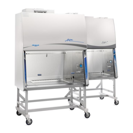
Advertisement
Quick Links
Please read user's manual before
operating equipment
Original Instructions
LABCONCO CORPORATION
8811 Prospect Avenue
Kansas City, MO 64132
(800) 821-5525 I +1 (816) 333-8811
labconco.com
Technical Manual
®
®
Logic+
and Cell Logic+
A2 | B2 Biosafety Cabinets
®
Axiom
C1 Biosafety Cabinets
®
PuriCare
Procedure Stations
Register this product
Advertisement
Table of Contents

Related Manuals for Labconco Logic+ A2


Summary of Contents for Labconco Logic+ A2
- Page 1 Please read user’s manual before operating equipment Original Instructions LABCONCO CORPORATION 8811 Prospect Avenue Kansas City, MO 64132 (800) 821-5525 I +1 (816) 333-8811 labconco.com Technical Manual ® ® Logic+ and Cell Logic+ A2 | B2 Biosafety Cabinets ® Axiom C1 Biosafety Cabinets ®...
- Page 2 +® Logic Type A2 Biosafety Cabinets 30231xxx1 30241xxx1 30251xxx1 30261xxx1 30238xxx1 30248xxx1 30258xxx1 30268xxx1 30242xxx1 30252xxx1 30262xxx1 PuriCare ® Procedure Stations 31241xxx1 31261xxx1 31242xxx1 31252xxx1 31262xxx1 Logic +® Type B2 Biosafety Cabinets 30348xxx1 30368xxx1 Cell Logic +® Type A2 Biosafety Cabinets 32239xxx1 33239xxx1 34239xxx1...
- Page 3 Warranty Labconco Corporation provides a warranty to the original buyer for the repair or replacement of parts and reasonable labor as a result of normal and proper use of the equipment with compatible chemicals. Broken glassware and maintenance items, such as filters, gaskets, light bulbs, finishes and lubrication are not warranted.
-
Page 4: Table Of Contents
Table of Contents 1: INTRODUCTION Contacting Labconco About This Manual Theory of Operation Type A2 Type B2 Type C1 – A mode Type C1 – B mode 2: SAFETY PRECAUTIONS Typographical Conventions General Safety Precautions Safety Precautions for this Product... - Page 5 Data Plate Information 7: EXHAUST SYSTEM CONNECTIONS Exhaust Connection Best Practices Air-Tight Damper Exhaust System Requirements Type A2 Models Cell Logic+ Type A2 Models Type B2 Models Type C1 Models 8: CONFIGURATION Current Configuration Change Configuration 9: CALIBRATION Certifier Password Adjusting Blower Speed Adjusting the Internal Air Damper Setting the Filter Life Gauge...
- Page 6 Type A2 Supply HEPA Filter Leak Test Acceptance Criteria Type A2 Exhaust HEPA Filter Leak Test Acceptance Criteria Type B2 Supply HEPA Filter Leak Test Preparation Theoretical Upstream Concentration Upstream Concentration Sampling Type B2 Supply HEPA Filter Leak Test Acceptance Criteria Type B2 Exhaust HEPA Filter Leak Test Preparation Theoretical Upstream Concentration Type B2 Exhaust HEPA Filter Leak Test...
- Page 7 UV Light Intensity Test (optional) Acceptance Criteria Ground Fault Circuit Interrupter (GFCI) Test Acceptance Criteria 11: QUICKCHARTS QuickChart – Type A2 3-ft & 4-ft QuickChart – Type A2 5-ft & 6-ft Type A2 Footnotes QuickChart – Type B2 Type B2 Footnotes QuickChart –...
- Page 8 UV Lamp Socket Replacement Type B2 Prefilter Replacement Air-Tight Damper Adjustment Preparing the Biosafety Cabinet for Gaseous Sterilization Service Fixture Installation & Service Connection 13: ELECTRICAL COMPONENTS Electronics Module Electronic Module Components Resetting a Circuit Breaker Power Supply Board Display Board Speaker Blower Motor Wiring Diagrams...
- Page 9 Airflow Sensor (optional) Canopy (optional) 16: BMS DATA OUTPUT CONNECTION Connection Type Data Output Format Data Output Rate Data Output String Definition Data Output Software Requirements 17: VENTUS CANOPY CONNECTION KIT Kit Catalog Numbers Installation Procedure Exhaust Damper Installation Procedure Canopy Switch Wiring Connection Calibrate for Operation 18: AIRFLOW SENSOR KIT...
- Page 10 20: IV BAR KIT Kit Catalog Numbers Installation 21: PREFILTER KIT Kit Catalog Numbers (Type A2 and B2 only) Installation Attach Prefilter(s) to Towel Catch – G4 Paper Attach Prefilter(s) to Towel Catch – Aluminum Washable 22: EN ALARM/RELAY CONTACT KIT Installation Example 1 –...
-
Page 11: 1: Introduction
Logic+, Cell Logic+ and Axiom biosafety cabinets, and Puricare procedure stations. As always, we at Labconco want to assist you in a better understanding of our products and their operation; if you have any questions, or need additional information, please contact us. -
Page 12: About This Manual
About This Manual This manual contains technical information for all types and models of Labconco biosafety cabinets and procedure stations. Type A2 biosafety cabinets with a 12 inch sash operating height, and C1 biosafety cabinets utilize two internal blowers, and Type A2 and B2 biosafety cabinets with sash operating heights of 8, 9, or 10 inch utilize one internal blower. -
Page 13: Type B2
Type B2 All Logic+ Type B2 biosafety Figure 1-2 cabinets meet the airflow requirements of ANSI/NSF Standard 49. All of the air in the cabinet is filtered and none is recirculated. All Type B2 Logic+ biosafety cabinets feature intrinsically safe designs, with all contaminated areas under negative pressure. -
Page 14: Type C1 - B Mode
Type C1 – B mode All Logic+ Type C1 biosafety Figure 1-4 cabinets meet the airflow requirements of ANSI/NSF Standard 49. The Chem-Zone (center work surface) air is filtered and exhausted via a remote building exhaust system, while the inflow and outer work surface air is filtered and recirculated. -
Page 15: 2: Safety Precautions
2: Safety Precautions Before unpacking, installing, operating, maintaining, or servicing this equipment, read the following safety warnings and precautions. Avant le déballage, l’installation, le fonctionnement, l’entretien ou la maintenance de cet équipement, lire les avertissements de sécurité et les précautions d’emploi. –... - Page 16 – Air or components that will be very hot. BURN RISK (HIGH TEMPERATURE) Take care not to touch these defined areas. Failure to avoid these areas may result in moderate to severe injury. – Air ambiant ou RISQUE DE BRÛLURE (TEMPÉRATURE ÉLEVÉE) composant devenant très chaud.
-
Page 17: General Safety Precautions
– Do not lift or move this equipment without assistance. LIFTING HAZARD – Ne pas soulever ou déplacer cet équipement sans DANGER DE LEVAGE assistance. – Magnets or magnetic field present. MAGNETIC FIELD IN USE – Présence d'aimants ou de champ CHAMP MAGNETIQUE UTILISE magnétique. - Page 18 Never contact moving parts with your person. Failure to avoid moving parts will result in moderate to serious injury, death, or damage to property. Ne jamais toucher les parties mobiles. Le non-respect de la consigne consistant à éviter les pièces mobiles peut entraîner des blessures graves, la mort ou des dommages matériels.
-
Page 19: Safety Precautions For This Product
If your application requires loading more than 150 lbs. (68 kg), contact Labconco’s Product Service Department at 800- 821-5525 or 816-333-8811 for assistance. - Page 20 HEPA filter during installation or normal operation. If you suspect that a HEPA filter has been damaged, DO NOT use the cabinet; contact a local certification agency or Labconco at 800-821-5525 or 816-333-8811 for re- certification information. The HEPA filters in the biosafety cabinet will gradually accumulate airborne particulate matter from the room and from work performed in the cabinet.
-
Page 21: 3: Catalog Number Configurator
3: Catalog Number Configurator Logic+ and Axiom biosafety cabinets and Puricare procedure stations utilize catalog numbers (also referred to as model numbers) where each digit of the catalog number provides key information about the model. Use the configurator below to identify specifics about your product. -
Page 22: 4: Serial Tag
4: Serial Tag If you need to contact Labconco regarding this product, it is required you provide the serial number. The serial number provides all product details, including the revision level under which the product was constructed. It is the single, most important piece of information when assistance is requested. -
Page 23: Serial Tag Information
Serial Tag Information The following information is located on the Serial Tags: Primary Serial Tag Figure 4-2 Serial Number Catalog (Model) Number Revision Electrical Requirements o Voltage o Frequency o Amperage o Phase Figure 4-3 Secondary Serial Tag ... -
Page 24: 5: Factory Test Report
5: Factory Test Report The factory test report is a valuable reference for the product’s airflows and blower setting(s), as well as information about the HEPA filters, and accessories that may be factory installed. Test Report Location The test report is located on the blower/plenum cover, which is behind the front dress panel. -
Page 25: Test Report Information
Test Report Information See Figure 5-2 for a typical test report. Review this carefully to identify where on the report specific information is located. Important information is highlighted below. Figure 5-2 Catalog Serial Blower Number Number Speed(s) Inflow (Avg. Velocity) Downflow (Avg. -
Page 26: 6: Additional Product Information
6: Additional Product Information All NSF-Listed biosafety cabinets are required by NSF49 regulations to display a Data Plate on the front of the product in a readily visible location. Data Plate Location See Figure 6-1 for the Data Plate location. Figure 6-1 Primary Serial Tag... -
Page 27: Data Plate Information
NSF49 standard revision under which the biosafety cabinet is listed Figure 6-2 shows a Type A2, 4-feet width Data Plate as an example to identify where the required information is located on the Data Plate. All Labconco Data Plates are in the same format. -
Page 28: 7: Exhaust System Connections
7: Exhaust System Connections Not all models of biosafety cabinets are connected to a remote or building exhaust system. Type A2 models may recirculate their exhaust back to the laboratory, or remove their exhaust air from the lab via a Ventus Canopy (also referred to as a Thimble Connection) connected to a remote (building) exhaust system. - Page 29 Figure 7-2 Avoid cabinet locations that require an elbow directly above the cabinet’s exhaust connection or an excessive number of elbows in the exhaust system. There should be a straight length 10 duct diameters long between the cabinet connection and any elbow, and between subsequent elbows.
-
Page 30: Air-Tight Damper
Air-Tight Damper On canopy-exhausted Type A2 and C1 (operating in B-mode) models, Labconco highly recommends installing an air-tight damper above each biosafety cabinet when connected to a building exhaust system. The air-tight damper allows for fine adjustment of the exhaust air volume provided, in order to correctly set the necessary exhaust airflow for each biosafety cabinet. -
Page 31: Exhaust System Requirements
Exhaust System Requirements The exhaust system must be capable of moving the following volumes of exhaust air at the negative pressures listed. The Airflow Volumes are the values recorded via direct measurement using a flow hood at the front opening of the cabinet. The Concurrent Balance Values are measured in the exhaust duct via traverse methodology, and will always be higher due to differences in volume measurement methodologies. -
Page 32: Cell Logic+ Type A2 Models
Cell Logic+ Type A2 Models Table 7-2 Concurrent Recommended Airflow Volume Balance Value Duct Vacuum Logic+ Type A2 Model /min /min 3-foot, 9" Sash 0.15 4-foot, 9" Sash 0.15 5-foot, 9" Sash 0.15 6-foot, 9" Sash 0.15 1: Unlike Type B biosafety cabinets, the recommended vacuum will remain constant throughout the life of the exhaust HEPA filter. -
Page 33: Type C1 Models
Type C1 Models Table 7-4 Concurrent Recommended Airflow Volume Balance Value Duct Vacuum Axiom Type C1 Model /min /min 4-foot, 8" Sash 0.30 4-foot, 10" Sash 0.30 6-foot, 8" Sash 0.30 6-foot, 10" Sash 1162 0.30 1: Unlike Type B biosafety cabinets, the recommended vacuum will remain constant throughout the life of the exhaust HEPA filter. -
Page 34: 8: Configuration
8: Configuration This section provides instructions to access and understand the current configuration of the biosafety cabinet, and make changes to the configuration. Keypad button presses are shown as [BLUE WITH BRACKETS]. Menu screen selections are shown as green italics. Current Configuration It is important to understand the current configuration of the biosafety cabinet for many reasons, some of which include:... - Page 35 2. The Info icon should be highlighted, if not select Info, press [OK/MUTE]. Sash Type Info Height C1 - A MODE [OK/MUTE] 10 INCH Option(s) UV LIGHT CANOPY Installed Software REV. D Version [UP] [DOWN] Only shown on two blower models (A2 12-inch and C1) Blower SUPPLY...
-
Page 36: Change Configuration
Change Configuration Changes to the biosafety cabinet configuration can be made in the field. This typically occurs after an accessory is field installed, or the user requests a change to the sash height (between 8 and 10 inches) on a Type C1 only. Never change the following configuration parameters: ... - Page 37 3. From the Warning Screen, press [OK/MUTE] to acknowledge the warning that the following screens are restricted. 4. On the Password Screen, enter the password: [LIGHT] [UV LIGHT] [TIMER] [TIMER] [OK/MUTE]. Password Entered CONFIGURATION PASSWORD CALIBRATION * * * * * Configuration should be highlighted, if not, select it, press [OK/MUTE].
- Page 38 6. On a Type A2 or C1 only, if field installing, or removing the Airflow Sensor, change the selection accordingly, press [OK/MUTE]. [OK/MUTE] UV LIGHT AIRFLOW SENSOR UV LIGHT AIRFLOW SENSOR 7. On all biosafety cabinet types, if field installing, or removing the UV Light, change the selection accordingly (screen shown above), press [OK/MUTE].
- Page 39 10. If a Type C1 model, and B-Mode operation was selected previously, the Active Protection Screen will appear. This allows the selection of the time for which the Type C1 will continue to operate (while sounding an alarm) when a remote (building) exhaust failure occurs.
-
Page 40: 9: Calibration
9: Calibration This section provides instructions to access and understand the procedures to calibrate the biosafety cabinet. Use this section in conjunction with Section 10: Certification when performing initial or annual certification. Never enter the password-protected area, or change settings of the biosafety cabinet if you are not a trained and qualified certifier or technician. -
Page 41: Adjusting Blower Speed
Adjusting Blower Speed During initial or annual certification of the biosafety cabinet, the blower speed may need to be adjusted. Blower speed must only be adjusted by a trained, qualified certifier. To adjust the blower speed, following these instructions. 1. From the Main Menu, press [MENU], using [UP] [DOWN] select the... - Page 42 4. On the Password Screen, enter the password: is [LIGHT] [UV LIGHT] [TIMER] [TIMER] [OK/MUTE]. If also installing a new airflow sensor, see Certifier Password earlier in this section to enter the correct password to allow for zero- point calibration of the airflow sensor. Password Entered CONFIGURATION...
-
Page 43: Adjusting The Internal Air Damper
Adjusting the Internal Air Damper On Type A2 8-inch through 10-inch sash heights and all Type B2 (single blower) models, during the certification of the biosafety cabinet, it may be necessary to adjust the split of air between downflow and exhaust. This is an important part of balancing the biosafety cabinet and hitting the specified average downflow and inflow values specified for each model and size cabinet. - Page 44 2. Locate the exhaust damper adjustment bolt (reference Figure 9-2). The adjustment bolt is in the center of a flexible, orange cup seal. Use a 7/16-inch nut driver or socket and ratchet to turn the bolt. The bolt has 16 turns from fully open to fully closed.
-
Page 45: Setting The Filter Life Gauge
Setting the Filter Life Gauge During initial or annual certification of the biosafety cabinet, and after the HEPA filters are changed, the Filter Life Gauge may need to be reset. There are three options to choose from when resetting the Filter Life Gauge. Below are the three options, and an explanation on which to select. -
Page 46: Type A2 (12-Inch Sash) And Type C1
Type A2 (12-inch sash) and Type C1 1. On the Supply Blower Speed screen, press [OK/MUTE]. SUPPLY [OK/MUTE] SUPPLY NEW FILTER CURRENT RPM = 1217 SAME FILTER AVERAGE RPM = 1219 SET FILTER LIFE ‘OK’ TO CONTINUE ‘OK’ displayed when blower speed stabilizes 2. -
Page 47: Airflow Sensor Calibration
Airflow Sensor Calibration All Type B2 biosafety cabinets have an airflow sensor to sense the exhaust air pulled from the cabinet by the remote (building) exhaust system. Type A2 and C1 biosafety cabinets may have an airflow sensor as an optional accessory. Unless installing or replacing the airflow sensor, the zero point should be correctly set from the factory (see Zero Point Calibration later in this section). -
Page 48: Type B2
3. Using the average downflow velocity measured during airflow certification, use [UP] [DOWN] to adjust the Nominal Downflow Value to match this measured velocity. The Nominal Downflow Value will flash, and it will be displayed in feet per minute (FPM) or meters per second (M/S) based on the desired units selected in the Settings submenu. - Page 49 3. The nominal set point for Inflow has been set in the previous step. Now the alarm set point must be established. The screen below is displayed. While on this screen, reduce the remote or building exhaust system until the TOTAL volume of air drawn by the remote exhaust system is reduced to 90% of nominal.
-
Page 50: Zero Point Calibration
Zero Point Calibration If a new airflow sensor is being calibrated (field installation or replacement), a zero point calibration will be performed. To gain access to the Zero Point Calibration screens, a different password must be entered on the Password Screen. -
Page 51: Vacuum Start Switch Calibration (Type C1 Only)
Vacuum Start Switch Calibration (Type C1 only) A Type C1 biosafety cabinet operating in B-mode must sense sufficient remote exhaust volume before starting the internal blowers. This is accomplished with the Vacuum Start Switch (VSS) located in the exhaust housing of the biosafety cabinet. After setting the Filter Life Gauge, or calibrating the Airflow Sensor (if present), a Type C1 biosafety cabinet will ask if the VSS needs to be calibrated. - Page 52 1. After selecting on the screen to the left below and pressing [OK/MUTE], watch the Inlet Relief Valve and slowly reduce the remote exhaust system flow until the Inlet Relief Valve begins to flutter, but is not completely closed. Hold the remote exhaust system flow at this point.
-
Page 53: 10: Certification
10: Certification This section provides instructions to certify the biosafety cabinet. Use this section in conjunction with Section 9: Calibration when performing initial or annual certification. Never enter the password-protected area, or change settings of the biosafety cabinet if you are not a trained and qualified certifier or technician. Changing parameters in the password-protected area may impair the product’s performance and result in loss of protection and/or harm or death to personnel in the laboratory. -
Page 54: Theoretical Upstream Concentration
If the biosafety cabinet has been used with biohazards, toxic chemicals, or radioisotopes, the Upstream Sample Tube cannot be used (Figure 10-1). Testing at Labconco has shown the actual concentration varies from the theoretical value. Table 10-1 shows the actual vs. calculated concentrations for Type A2 models. Establish the 100% and 0% concentration levels for the photometer using the actual values provided in Table 10-1 for the model being tested. - Page 55 Table 10-1 Actual Sash Laskin Calculated Type A2 Concentration Height Displacement Nozzles Concentration Cabinet Width (ug/L) (inches) (CFM) Required (ug/L) 3-foot 4-foot 5-foot 1000 1130 1100 1140 6-foot 1200 1350 The calculated concentration was established using the formula: Concentration (ug/l) = (# Laskin nozzles @ 23 PSIG x 13,500) / Volume of air displaced Based on Mineral oil...
-
Page 56: Type A2 Supply Hepa Filter Leak Test
Type A2 Supply HEPA Filter Leak Test During this test the supply HEPA filter will be challenged and scanned to check for leaks. This section describes how to access and test the supply HEPA filter on a Type A2 biosafety cabinet. The aerosol generator and photometer should be prepared at this point as described in the preparation steps listed in the previous section. -
Page 57: Acceptance Criteria
5. Open the correct number of Laskin Nozzles on the aerosol generator (refer to Table 10-1). 6. Scan the downstream side of the supply HEPA filter by passing the sampling nozzle in slightly overlapping strokes over the entire surface of the filter. The sampling nozzle must be no more than 1 inch from the surface of the filter media. -
Page 58: Type A2 Exhaust Hepa Filter Leak Test
Type A2 Exhaust HEPA Filter Leak Test During this test the exhaust HEPA filter will be challenged and scanned to check for leaks. This section describes how to access and test the exhaust HEPA filter on a Type A2 biosafety cabinet. The aerosol generator and photometer should be prepared at this point as described in the preparation steps listed in the previous section. -
Page 59: Acceptance Criteria
Note: When scanning the edges of the exhaust HEPA filter, photometer operation may become erratic due to the aspiration of room air into the exhaust air stream. This problem can be minimized or eliminated by placing the edge of a sheet of rigid plastic or metal just outside the edge of the HEPA filter when scanning the filter edges. -
Page 60: Type B2 Supply Hepa Filter Leak Test Preparation
If you do not wish to connect the Upstream Sampling Tube to the photometer to establish the actual 100% concentration value, the theoretical value will need to be used instead. Testing at Labconco has shown the actual concentration varies from the theoretical value. Table 10-2 shows the actual vs. calculated concentrations for Type B2 models. - Page 61 Place aerosol generator here Figure 10-9 Figure 10-10 Pre-Filter Thumbnuts (2) Table 10-2 Actual Sash Supply Air Laskin Calculated Type B2 Concentration Height Displacement Nozzles Concentration Cabinet Width (ug/L) (inches) (CFM) Required (ug/L) 4-foot 6-foot The calculated concentration was established using the formula: Concentration (ug/l) = (# Laskin nozzles @ 23 PSIG x 13,500) / Volume of air displaced Based on Mineral oil...
-
Page 62: Type B2 Supply Hepa Filter Leak Test
Type B2 Supply HEPA Filter Leak Test During this test the supply HEPA filter will be challenged and scanned to check for leaks. This section describes how to access and test the supply HEPA filter on a Type B2 biosafety cabinet. The aerosol generator and photometer should be prepared at this point as described in the preparation steps listed in the previous section. -
Page 63: Acceptance Criteria
5. Open the correct number of Laskin Nozzles on the aerosol generator (refer to Table 10-2). 6. Scan the downstream side of the supply HEPA filter by passing the sampling nozzle in slightly overlapping strokes over the entire surface of the filter. The sampling nozzle must be no more than 1 inch from the surface of the filter media. -
Page 64: Type B2 Exhaust Hepa Filter Leak Test Preparation
Theoretical Upstream Concentration Actual upstream sampling is not possible on a Type B2 exhaust filter, so the theoretical concentration will be used. Testing at Labconco has shown the actual concentration varies from the theoretical value. Table 10-3 shows the actual vs. calculated concentrations for Type B2 models. -
Page 65: Type B2 Exhaust Hepa Filter Leak Test
Table 10-3 Actual Sash Exhaust Air Laskin Calculated Type B2 Concentration Height Displacement Nozzles Concentration Cabinet Width (ug/L) (inches) (CFM) Required (ug/L) 4-foot 6-foot 1083 The calculated concentration was established using the formula: Concentration (ug/l) = (# Laskin nozzles @ 23 PSIG x 13,500) / Volume of air displaced Based on Mineral oil Type B2 Exhaust HEPA Filter Leak Test During this test the exhaust HEPA filter will be challenged and a downstream average... -
Page 66: Type C1 Supply Hepa Filter Leak Test Preparation
If you do not wish to connect the Upstream Sampling Tube to the photometer to establish the actual 100% concentration value, the theoretical value will need to be used instead. Testing at Labconco has shown the actual concentration varies from the theoretical value. Table 10-4 shows the actual vs. calculated concentrations for Type C1 models. - Page 67 Sampling Tube and sample the upstream concentration to establish the 100% concentration level. 4. Establish the 0% concentration level according to your photometer’s instructions. Extension Tube Figure 10-16 Figure 10-17 Center Drip Tray Table 10-4 Actual Sash Supply Air Laskin Calculated Type C1 Concentration...
-
Page 68: Type C1 Supply Hepa Filter Leak Test
Type C1 Supply HEPA Filter Leak Test During this test the supply HEPA filter will be challenged and scanned to check for leaks. This section describes how to access and test the supply HEPA filter on a Type C1 biosafety cabinet. The aerosol generator and photometer should be prepared at this point as described in the preparation steps listed in the previous section. -
Page 69: Acceptance Criteria
5. Open the correct number of Laskin Nozzles on the aerosol generator (refer to Table 10-4). 6. Scan the downstream side of the supply HEPA filter by passing the sampling nozzle in slightly overlapping strokes over the entire surface of the filter. The sampling nozzle must be no more than 1 inch from the surface of the filter media. -
Page 70: Type C1 Exhaust Hepa Filter Leak Test Preparation
Theoretical Upstream Concentration Actual upstream sampling is not possible on a Type C1 exhaust filter, so the theoretical concentration will be used. Testing at Labconco has shown the actual concentration varies from the theoretical value. Table 10-5 shows the actual vs. calculated concentrations for Type C1 models. - Page 71 Figure 10-22 Table 10-5 Actual Sash Exhaust Air Laskin Calculated Type C1 Concentration Height Displacement Nozzles Concentration Cabinet Width (ug/L) (inches) (CFM) Required (ug/L) 4-foot 6-foot The calculated concentration was established using the formula: Concentration (ug/l) = (# Laskin nozzles @ 23 PSIG x 13,500) / Volume of air displaced Based on Mineral oil...
-
Page 72: Type C1 Exhaust Hepa Filter Leak Test
Type C1 Exhaust HEPA Filter Leak Test During this test the exhaust HEPA filter will be challenged and a downstream average utilized to check for leaks. This section describes how to test the exhaust HEPA filter on a Type C1 biosafety cabinet. The aerosol generator and photometer should be prepared at this point as described in the preparation steps listed in the previous section. -
Page 73: Acceptance Criteria
5. Observe the average concentration of aerosol downstream. Acceptance Criteria Aerosol penetration shall not exceed 0.01%. Reinstall the exhaust housing front plate, unsecure temporary Inlet Relief Valve hold open, reinstall the work surface pieces. -
Page 74: Downflow Velocity
Downflow Velocity All models of Labconco biosafety cabinets are classified as uniform downflow, as tested per the current NSF Standard 49. This section describes how to prepare and test the downflow velocity on all Types of biosafety cabinets. Before setting up the downflow velocity test, if any accessories are installed inside the biosafety cabinet (UV lamp, IV Bar, etc.), remove them for this test. -
Page 75: Acceptance Criteria
Table 10-6 Type Sash Downflow Distance Test Grid Height Average in inches (cm) A2 & B2 Cabinet Total Test Rows x From Back Between Between Width inches FPM (m/s) Points Columns & Sides Rows Columns 8, 9 55 (.28) 3 x 7 6.0 (15) 5.75 (14.6) 4.08 (10.4) -
Page 76: Inflow Velocity
Thumbnuts 1. Start the blower(s), ensure the sash is at the correct operating height. 2. Attach the Labconco Holder Bracket Assembly to the front grille centered left-to- right on the biosafety cabinet. Loosen the two Thumbnuts to create a gap between the two plates. - Page 77 4. Lower the sash until the skirt frame rests on the inside of the glass and remains in place. A tall stand may be used to support the opposite end of the DIM if desired. 5. If a sash alarm occurs, press [OK/MUTE]. 6.
-
Page 78: Acceptance Criteria
Table 10-7 Type Sash Inflow Inflow Sash Open Area Inflow Volume Range A2 & B2 Height Average Volume Cabinet Width inches FPM (m/s) 2.03 0.19 203-223 345-379 3-foot 2.28 0.21 228-251 387-426 2.53 0.24 253-278 430-472 2.69 0.25 269-296 457-503 3.03 0.28 303-333... -
Page 79: Secondary Method
‘+’ engraved under the width number. For example, if a 4-ft model is under test, select the two Sash Stops engraved with a ‘4 +’. 2. Place the thermal anemometer probe into the Labconco Holder Bracket Assembly. For convenience, the 6-ft Sash Stops have two lines to position the tip of the thermal anemometer correctly in the Holder. - Page 80 3. Insert the appropriate left and right stop into the recess in each corner post, as shown in Figure 10-31. Lower the sash until it contacts the Sash Stops. Figure 10-31 Sash Stop (Same opposite end) Row of Holes 4. Locate the single row of holes at the front-most edge of the grille, see Figure 10- 5.
- Page 81 7. Place the thermal anemometer, now secured to the Labconco Holder, onto the grille. The two pins in the Holder will drop into two holes on the grille. The thermal anemometer probe should line up with the test point mark made earlier.
- Page 82 15. Average all the readings. Apply the wind tunnel correction and local condition corrections factors to the average velocity reading. 16. Multiply the average inflow velocity by the column “Correction Factor” based on Type and model in Table 10-8. Table 10-8 Sash Type Sash...
-
Page 83: Acceptance Criteria
17. Compare the inflow volume in CFM calculated in step #15 with the value in column “Corrected Inflow Volume Range” based on Type and model shown in Table 10-8. 18. If the Inflow Volume is not within the acceptance criteria range, adjust the biosafety cabinet according to Adjusting the Blower Speed and/or Adjusting the Internal Damper found in Section 9:... -
Page 84: Work Area Air Cleanliness Test (Optional)
Work Area Air Cleanliness Test (optional) Air cleanliness is a measurement of all particles (greater than or equal to 0.5 micron in size) in the air. This is not an NSF Standard 49 test. However, if the end user would like to verify air cleanliness in the work area, follow these instructions: 1. -
Page 85: Lighting Test (Optional)
Lighting Test (optional) The light intensity should be measured as described in the current NSF/ANSI Standard 49 Annex F. To test the light intensity at the biosafety cabinet’s work surface, follow these instructions: Note: A light meter that is color- and cosign-corrected must be used for accurate results. -
Page 86: Noise Test (Optional)
Noise Test (optional) The noise (sound pressure) should be measured as described in the current NSF/ANSI Standard 49 Annex F. To test the biosafety cabinet’s noise level, follow these instructions: 1. Establish the sound meter location, as follows: a. On the left-to-right centerline of the biosafety cabinet b. -
Page 87: Uv Light Intensity Test (Optional)
UV Light Intensity Test (optional) To test the biosafety cabinet’s UV light intensity level at the work surface, follow these instructions: Note: The UV radiometer must measure light at a wavelength of 254 nm to proceed with this test. 1. Mark the geometric center of the work surface. 2. -
Page 88: Ground Fault Circuit Interrupter (Gfci) Test
Ground Fault Circuit Interrupter (GFCI) Test To test the biosafety cabinet’s internal GFCI outlets, follow these instructions: This test may only be applied on 100-115v models. 208-230v models do not contain GFCI outlets internal to the biosafety cabinet. Note: The GFCI tester must be capable of simulating a fault of 3mA. 1. -
Page 89: 11: Quickcharts
11: QuickCharts The QuickCharts section provides a central location for all critical data and specifications of all biosafety cabinet types and models. The data included on these charts includes: downflow, inflow, building exhaust system requirements, HEPA filter specifications and leak test parameters. The charts are provided in imperial (English) units only. -
Page 90: Quickchart - Type A2 3-Ft & 4-Ft
1200 1850 1850 1850 1850 Glass Type Frosted Frosted Frosted Frosted Frosted Frosted Frosted Ventus Canopy Data Labconco Canopy P/N 3889200 3889200 3889200 3889201 3889201 3889201 3889201 Canopy Slot Area (ft Nominal Canopy Inflow (CFM) 240-260 240-260 240-260 240-260 240-260... -
Page 91: Quickchart - Type A2 5-Ft & 6-Ft
3200 3200 Glass Type Frosted Frosted Frosted Frosted Frosted Frosted Frosted Frosted Ventus Canopy Data Labconco Canopy P/N 3889202 3889202 3889202 3889202 3889203 3889203 3889203 3889203 Canopy Slot Area (ft Nominal Canopy Inflow (CFM) Nominal Canopy Slot Velocity (FPM) 240-260... -
Page 92: Type A2 Footnotes
Without gasket Motor / Blower Specifications Each motor must be programmed by Labconco for the appropriate width cabinet. The PWM setting will fluctuate depending on local temperature and pressure. LED Lamp Specifications THIS PRODUCT USES DIRECT DRIVE T8 LED LAMPS INSTEAD OF FLUORESCENT LAMPS. THERE IS NO BALLAST;... -
Page 93: Quickchart - Type B2
(Avg. velocity x CF) Supply HEPA Filter Leak Test Data Air Displacement (CFM) Laskin Nozzles needed Theoretical aerosol conc. (ug/l) Actual aerosol conc. (ug/l) Supply HEPA Data Labconco P/N 3838401 3838403 Width x Depth x Height (in.) 48x18x3.06 72x18x3.06 Performance (CFM) Pressure Drop (in. -
Page 94: Type B2 Footnotes
Without gasket Motor / Blower Specifications Each motor must be programmed by Labconco for the appropriate width cabinet. The PWM setting will fluctuate depending on local temperature and pressure. LED Lamp Specifications THIS PRODUCT USES DIRECT DRIVE T8 LED LAMPS INSTEAD OF FLUORESCENT LAMPS. THERE IS NO BALLAST;... -
Page 95: Quickchart - Type C1
(Avg. velocity x CF) Supply HEPA Filter Leak Test Data Air Displacement (CFM) Laskin Nozzles needed Theoretical aerosol conc. (ug/l) Actual aerosol conc. (ug/l) Supply HEPA Data Labconco P/N 3838401 3838401 3838403 3838403 Width x Depth x Height (in.) 48x18x3.06 48x18x3.06... -
Page 96: Type C1 Footnotes
Without gasket Motor / Blower Specifications Each motor must be programmed by Labconco for the appropriate width cabinet. The PWM setting will fluctuate depending on local temperature and pressure. LED Lamp Specifications THIS PRODUCT USES DIRECT DRIVE T8 LED LAMPS INSTEAD OF FLUORESCENT LAMPS. THERE IS NO BALLAST;... -
Page 97: 12: Advanced Service Procedures
12: Advanced Service Procedures This section provides instructions to perform advanced service procedures on the biosafety cabinet. Such procedures include changing HEPA filters, adjusting the sash or sash position sensors, replacing LED or UV lamps, and more. Tools Required #2 Phillips screwdriver or #2 Phillips bit (4 inches long minimum) ... -
Page 98: Removal Of External Dress Panels
Removal of External Dress Panels To access the HEPA filters, LED lamps, sash sensors, the LCD display, and other service areas, the front panel and side panels will be removed. This section describes removal of the external dress panels. Dress Panel 1. -
Page 99: Side Panels
Side Panels 1. Locate and remove the two Phillips screws along the front edge of each side panel. Figure 12-2 Left Product illustration Side may not accurately Screw Location represent all models Panel Right Side Panel Screw Location 2. The side panels will hinge open once the screws are removed. 3. -
Page 100: Front Sash
Front Sash The glass sash utilizes a cable and pulley system with counter weights located in the right and left end service compartments. This section describes adjustments or repairs to the sash or sash sensors. Sash Level Adjustment The sash and its two counter weights are joined together with two sash cables, one per counter weight. -
Page 101: Sash Sensor Adjustment Or Replacement
Sash Sensor Adjustment or Replacement The biosafety cabinet senses the sash’s vertical position with mechanical switches located on the counterweight channel in the right end service compartment. The switches activate off of the counterweight as it travels in the channel. These switches are reliable and do not require calibration. - Page 102 3. If the blower is on, turn it off, and turn off other noise producing equipment nearby. This step involves listening for a click from each switch. Check each switch function by slowly raising and lowering the sash. Check each switch to see if an audible click is heard when the sash is at key positions: a.
- Page 103 4. If operation is not as described in Step 3, repeat Step 3, positioning yourself to view the silver, formed tabs on each sash switch. Watch as the counterweight approaches each switch. Here is the expected behavior: a. CLOSED and ALMOST CLOSED (if present) switches – The silver tab should engage and rotate away from the sash counterweight, with the click occurring as soon as the point of the V-shaped silver tab reaches the top of the counterweight.
-
Page 104: Hepa Filter Replacement
HEPA Filter Replacement The HEPA filters load with particulate as the biosafety cabinet operates. Eventually, the filters will need to be replaced. Only replace a HEPA filter if you are a qualified and trained certifier or technician. The HEPA filters on a biosafety cabinet will be contaminated with biohazardous material. - Page 105 5. Remove the last two screws. The blower/plenum cover will rest on the center sash support (Figure 12-8) after the final screws are removed. Gently break the gasket seal on the cover by starting in one corner. Use a flat screwdriver if necessary, taking care not to damage the gasket or panel by prying too hard in one area.
- Page 106 7. Slide the exhaust HEPA filter straight out of the biosafety cabinet. 8. To remove the supply HEPA filter, the exhaust HEPA filter must be removed first. Using a 1/2-inch socket, tighten the 3 plenum lift bolts (turning each bolt clockwise will raise the plenum) until the plenum raises 1/2-inch (13 mm).
-
Page 107: Type A2 (12-Inch Sash)
Type A2 (12-inch sash) Follow these instructions carefully, and in the order documented. HEPA filters can be awkward to handle, and quite heavy for larger models. Use safe lifting techniques when removing and replacing the filters. Always use two persons to remove and replace each HEPA filter. - Page 108 6. To remove the exhaust HEPA filter, use a 1/2-inch socket to loosen the 4 bolts on top of the cabinet liner (Figure 12-13) until filter drops 1/2 inch to 3/4 inch (19 mm). Do not remove these 4 bolts, just loosen them to lower the exhaust filter. Top of cabinet Figure 12-13 Exhaust Filter Bolts...
- Page 109 9. Remove the 3 supply HEPA filter retainer brackets (see Figure 12-15). Figure 12-15 Filter Retainer Bracket 10. Lift up on one corner of the supply HEPA filter to break the seal between the filter gasket and the filter shelf. Once the filter is free, slide it straight out. Reinstallation Notes: 1.
-
Page 110: Type B2
Type B2 Follow these instructions carefully, and in the order documented. HEPA filters can be awkward to handle, and quite heavy for larger models. Use safe lifting techniques when removing and replacing the filters. Always use two persons to remove and replace each HEPA filter. 1. - Page 111 Figure 12-17 Exhaust Filter Bolts 6. To remove the supply HEPA filter, loosen all of the Phillips screws around the perimeter of the blower/plenum cover. Remove all screws except two along the top edge of the cover. This will support the cover. The sash stop bracket is held in place by two of the blower/plenum cover screws.
- Page 112 8. Use a 1/2-inch socket on the right end lift bolt and a 7/16-inch socket on the left end lift bolt, tighten the 2 plenum lift bolts (turning each bolt clockwise will raise the plenum) until the plenum raises 1/2-inch (13 mm). See Figure 12-19 for reference.
- Page 113 Reinstallation Notes: 1. When reinstalling the supply HEPA filter, to lower the plenum onto the supply HEPA, turn the 2 plenum lift bolts counter-clockwise. Turn each bolt part way, working back and forth between the 2 bolts to lower the plenum evenly. 2.
-
Page 114: Type C1
Type C1 Follow these instructions carefully, and in the order documented. HEPA filters can be awkward to handle, and quite heavy for larger models. Use safe lifting techniques when removing and replacing the filters. Always use two persons to remove and replace each HEPA filter. 1. - Page 115 Figure 12-22 Exhaust Filter Bolts 6. To remove the supply HEPA filter, loosen all of the Phillips screws around the perimeter of the blower/plenum cover. Remove all screws except two along the top edge of the cover. This will support the cover. The sash stop bracket is held in place by two of the blower/plenum cover screws.
- Page 116 9. To remove the supply HEPA filter, use a 1/2-inch socket to tighten the 3 plenum lift bolts (turning each bolt clockwise will raise the plenum) until the plenum raises 1/2-inch (13 mm). See Figure 12-24 for reference. Figure 12-24 Blower Lift Bolts, Left Lift Bolt, Right...
-
Page 117: Blower/Motor Replacement
Type A2 (8, 9, 10-inch sash) & B2 If replacing a blower/motor assembly, the motor must be programmed at Labconco. The blower/motor assembly must also be balanced by Labconco, and therefore it is strongly recommended to replace the blower/motor assembly, never the motor or blower individually. - Page 118 A2 ONLY - Figure 12-27 A2 ONLY - Figure 12-26 5. Remove the last two screws. The blower/plenum cover will rest on the center sash support (Figure 12-28) after the final screws are removed. Gently break the gasket seal on the cover by starting in one corner. Use a flat screwdriver if necessary, taking care not to damage the gasket or panel by prying too hard in one area.
- Page 119 7. Double check all power has been removed from the biosafety cabinet. 8. Disconnect the two (2) wire harness connections from the motor. The 5-pin connector, located closest to the blower, is released by depressing the locking tabs on either side of the connector. The 16-pin data connector is released by depressing the single locking tab in the center of the connector, on the side of the connector closest to the blower.
- Page 120 10. Grasp the motor and pull the assembly straight out of the biosafety cabinet. See Figure 12-31. Figure 12-31 Reinstallation Notes: 1. During reinstallation of the blower/motor assembly, angle the rear blower bracket into the plenum opening. Make sure this rear blower bracket is INSIDE the plenum opening.
-
Page 121: Type A2 (12-Inch Sash) & C1 Supply Blower/Motor
If replacing a blower/motor assembly, the motor must be programmed at Labconco. The blower/motor assembly must also be balanced by Labconco, and therefore it is strongly recommended to replace the blower/motor assembly, never the motor or blower individually. - Page 122 Figure 12-32 Blower Plenum Cover Center Sash Support 5. Locate the supply blower/motor assembly, it will be on the right side of the compartment, and resting atop the large, metal plenum. 6. Double check all power has been removed from the biosafety cabinet. 7.
- Page 123 8. Using a Phillips screwdriver, remove the two sealing plate screws and remove the sealing plate. See Figure 12-34. 9. Using a 1/2-inch socket or wrench, remove the two upper and one lower mounting bolts. See Figure 12-34. Figure 12-34 Upper Mounting Bolts...
-
Page 124: Type A2 (12-Inch Sash) & C1 Exhaust Blower/Motor
If replacing a blower/motor assembly, the motor must be programmed at Labconco. The blower/motor assembly must also be balanced by Labconco, and therefore it is strongly recommended to replace the blower/motor assembly, never the motor or blower individually. - Page 125 C1 – ONLY Figure 12-36 Exhaust Filter Cover Blower Plenum Cover 4. Using a 1/2-inch socket, loosen the 4 bolts on top of the cabinet liner (Figure 12- 37), until filter drops 1/2 inch to 3/4 inch (19 mm). Do not remove these 4 bolts, just loosen them to lower the exhaust filter.
- Page 126 6. Double check all power has been removed from the biosafety cabinet. 7. Disconnect the two (2) wire harness connections from the motor. The 5-pin connector, located closest to the blower, is released by depressing the locking tabs on either side of the connector. The 16-pin data connector is released by depressing the single locking tab in the center of the connector, on the side of the connector closest to the blower.
- Page 127 8. Loosen the four filter exhaust filter bolts until the exhaust plenum is free of the four bolts. See Figure 12-40. Top of cabinet Figure 12-40 Exhaust Filter Bolts Exhaust Filter Bolts It is recommended to have two persons perform Steps 8 and 9. When the exhaust filter bolts are freed from the exhaust plenum, it will fall without support.
- Page 128 10. The exhaust blower/motor assembly may be removed from the exhaust plenum at this point by removing the several thread-cutting, hex head screws located on the motor side of the exhaust plenum. Use a 5/16-inch socket or nut driver to remove these screws.
-
Page 129: Changing The Led Lamps
Changing the LED Lamps Before proceeding, make sure all electrical power has been removed from the cabinet by disconnecting the main electrical connection, which is the power cord. This product uses only LED direct drive lighting. Do NOT install fluorescent bulbs. 1. - Page 130 Figure 12-43 Spring Clip (2 per end) Note Dead Band (on LED Lamp) Socket Caps (2) 4. Pull each LED Lamp straight toward you to release the lamp from the two Spring Clips holding it in place (Figure 12-43). Note the rotational position of the old LED lamps (there is a dead band stripe that will need to be oriented the same when reinstalling the new LED Lamps).
-
Page 131: Led Lamp Socket Cap Replacement
LED Lamp Socket Cap Replacement If a lamp socket cap for the LED lamps is damaged and needs to be replaced, follow these instructions. 1. Unplug the cabinet from all electrical power. 2. Remove the front dress panel as described earlier in Removal of External Dress Panels. -
Page 132: Changing The Optional Uv Lamp
Changing the Optional UV Lamp The UV Lamp is an optional feature and may not be found on all models. THE UV LAMP IN THIS PRODUCT CONTAINS MERCURY Manage in accordance with local disposal laws. DO NOT place lamps in trash. Dispose as a hazardous waste. -
Page 133: Uv Lamp Socket Replacement
UV Lamp Socket Replacement If a lamp socket for the UV lamp is damaged and needs to be replaced, follow these instructions. 1. Start the cabinet blower and let it operate for 5 minutes. 2. Raise the sash to its full open position. 3. -
Page 134: Type B2 Prefilter Replacement
Type B2 Prefilter Replacement A Type B2 biosafety cabinet has a prefilter on top of the cabinet, to the left of the electronics module. This prefilter removes large particulate from the room air drawn into the biosafety cabinet by the supply blower. When this prefilter becomes loaded with particulate, replace it as follows. -
Page 135: Air-Tight Damper Adjustment
A remote exhaust connected Type A2 will require the Ventus Canopy Connection Kit installed for the air-tight damper to be installed above it. To adjust airflow on a Labconco air-tight damper follow these instructions. 1. Locate the damper adjustment blade (see Figure 12-47) on the air-tight damper. -
Page 136: Preparing The Biosafety Cabinet For Gaseous Sterilization
Preparing the Biosafety Cabinet for Gaseous Sterilization Note: This section only reviews the steps required for preparing the biosafety cabinet for gas sterilization. Thoroughly understand the sterilization procedures and protocols supplied by the manufacturer of the sterilizing system before attempting this operation. 1. -
Page 137: Service Fixture Installation & Service Connection
Tighten fully, taking care to position the compression end of the 90 degree fitting in the proper position to accept the customer-supplied tubing. Note: if a gas solenoid valve is ordered, the tubing between the 90 degree fitting and the solenoid is Labconco supplied. - Page 138 8. Close the petcock valve and leak check all connections with an inert gas and appropriate detector. If a leak is found, tighten the appropriate fitting connection further. Figure 12-48 Petcock Valve Coupling 90 Deg Fitting Solenoid Valve Solenoid Valve Tubing (optional) Coupling Nut...
- Page 139 12. Push the tube into the fitting until it is properly seated. The tube will go approximately ¾ inch (19 mm) into the fitting when properly seated. 13. Tighten the 90 degree fitting compression nut hand-tight and then, using a 7/16- inch wrench, tighten it at least ¾...
-
Page 140: 13: Electrical Components
13: Electrical Components This section details the electrical components found on the biosafety cabinet. Electronics Module The electronics module is located on the top, right side of the biosafety cabinet. To access the module, follow these instructions. 1. Remove all power from the biosafety cabinet by unplugging the power cord. 2. -
Page 141: Electronic Module Components
Electronic Module Components The electronics module contains the circuit breakers, AC relays, power supply board, transition I/O board, EN Alarm/Dry Relay Contact (optional), and UV lamp ballast (optional). These components are identified in Figure 13-1. Figure 13-1 Outlet Circuit Breaker(s) Cabinet Circuit Breaker(s) UV Lamp... -
Page 142: Resetting A Circuit Breaker
Resetting a Circuit Breaker Should an over current situation arise during normal operation, the circuit breakers located on the left side of the electronics module will trip, protecting the cabinet from damage. The biosafety cabinet offers internal outlets to power small devices inside the cabinet. The internal outlets are protected by one circuit breaker (two circuit breakers on 230v models), and the cabinet electronics are protected by a different circuit breaker (two different circuit breakers on 230v models). -
Page 143: Power Supply Board
Power Supply Board The power supply board converts the AC voltage supplied through the power cord to DC voltage to power the relays and microprocessor. It is an open-frame, dual output (5VDC and 12VDC) voltage power supply. If the power supply board is not operational or defective, the LCD Display will not power on, and the biosafety cabinet will not function. -
Page 144: Display Board
Display Board The LCD display and circuit board assembly contain the microprocessor which controls all functions of the biosafety cabinet. The data ribbon cable, keypad cable, and speaker cable all connect to the display board. To replace the display board, follow these instructions. -
Page 145: Speaker
Figure 13-5 Ribbon Cable Speaker Connector Connector Keypad Connector Speaker The speaker produces all audible alarms and tones. It connects to the display board. To replace the speaker, follow these instructions. 1. Disconnect the speaker wire connector from the display board. See Figure 13-4. 2. -
Page 146: Blower Motor
DC inside the motor. The motor is an ECM (electronically commutated motor), which is a brushless DC motor. The electronics head is programmed by Labconco for each particular model to operate in constant volume to deliver correct airflows even as the HEPA filter loads with particulate. If troubleshooting a non- responsive blower motor, use the following information. - Page 147 2. To verify the PWM measured in step 1 c (above) is correct, access the Tools submenu from the display. Follow the steps in Figure 13-8 to identify the PWM signal the microprocessor is sending to the blower motor. Figure 13-8 Info C1 - A MODE 10 INCH...
-
Page 148: Wiring Diagrams
Wiring Diagrams The wiring diagram is also located on the blower/plenum cover behind the dress panel. 100-115V... -
Page 149: 208-240V
208-240V... -
Page 150: 14: Troubleshooting
14: Troubleshooting This section details common troubleshooting for the biosafety cabinet. Blower and Lights not working... -
Page 151: Blower Only Will Not Start
Blower only will not start... -
Page 152: Lights Only Will Not Illuminate
Lights only will not illuminate... -
Page 153: Uv Light Will Not Illuminate
UV Light will not illuminate... -
Page 154: Airflow Alert Activating
Airflow Alert activating... -
Page 155: Filter Life Gauge Not At 100% When New
Filter Life Gauge not at 100% when new... -
Page 156: Contamination In The Work Area
Contamination in the work area... -
Page 157: 15: Diagnostics
15: Diagnostics This section details diagnostic functions available through the software of the biosafety cabinet. Sash Sensors 1. From the Home Screen, press [MENU]. 2. Press [UP] to select the Tools option. 3. Press [OK/MUTE] to enter the submenu. 4. Press [DOWN] until the Diagnostics... -
Page 158: Keypad
Keypad 1. From the Home Screen, press [MENU]. 2. Press [UP] to select the Tools option. 3. Press [OK/MUTE] to enter the submenu. 4. Press [DOWN] until the Diagnostics option is highlighted, then [OK/MUTE] to select the submenu. 5. Press [DOWN] to select the Keypad... -
Page 159: Airflow Sensor (Optional)
Airflow Sensor (optional) 1. From the Home Screen, press [MENU]. 2. Press [UP] to select the Tools option. 3. Press [OK/MUTE] to enter the submenu. 4. Press [DOWN] until the Diagnostics option is highlighted, then [OK/MUTE] to enter the submenu. 5. -
Page 160: Canopy (Optional)
Canopy (optional) 1. From the Home Screen, press [MENU]. 2. Press [DOWN] to select the Tools option. 3. Press [OK/MUTE] to enter the submenu. 4. Press [DOWN] until the Diagnostics option is highlighted, then [OK/MUTE] to enter the submenu. 5. Press [DOWN] until the Canopy... -
Page 161: 16: Bms Data Output Connection
16: BMS Data Output Connection The operation of the Logic+ Biosafety Cabinet can be monitored using a computer connected to the mini USB port on the side of the electronics module on top of the cabinet (see Figure 16-1). The remotely connected computer can monitor the cabinet, but not control the cabinet. -
Page 162: Data Output Format
Data Output Format To correctly receive data output from the Logic+ cabinet, set the following communication configurations on the receiving computer: 1. Data Rate = 9600 Baud 2. Word Length = 8-Bit 3. 1 Start Bit, 1 Stop Bit 4. No parity is transmitted 5. -
Page 163: Data Output String Definition
Data Output String Definition The data string is limited to 80 characters, including spaces and commas. Use Figure 16-4 to understand the character signficance. Figure 16-4 See Figure 16-5 on the following page for each character field’s value range. -
Page 164: Data Output Software Requirements
Figure 16-5 Data Output Software Requirements There are several commercially available software packages, which can read RS232- type data and enter the data into a computer program such as a word processor (to create a text file) or spreadsheet (to tabulate and plot the data). Consult your laboratory supply dealer regarding the latest software available. -
Page 165: 17: Ventus Canopy Connection Kit
17: Ventus Canopy Connection Kit To remote exhaust connect any Type A2 biosafety cabinet, the Ventus canopy connection kit must be utilized. The Ventus canopy system consists of a high efficiency, low profile canopy that interfaces directly with the Logic+’s control board. Ventus offers several features that are a distinct improvement over prior canopy designs: ... -
Page 166: Kit Catalog Numbers
Kit Catalog Numbers Table 17-1 Cabinet Catalog Width (Feet) Number 3-ft 3889200 4-ft 3889201 5-ft 3889202 6-ft 3889203 Installation Procedure NOTE: Before beginning this installation, Turn the unit on, press the [MENU] button, select Tools option, then Information. This will bring up the current settings screen. Record the motor(s) average RPMs once the unit operation stabilizes. - Page 167 4. Install the replacement brackets as shown, with the lockwashers, and tighten the acorn nuts. Reference Figure 17-4. 5. Carefully place the canopy between the brackets. Ensure the canopy fits on the inside of the two mounting brackets as shown. Line up the holes in the canopy connection with the threaded holes in the mounting bracket flanges.
-
Page 168: Exhaust Damper Installation Procedure
The air-tight damper shown is not supplied with the canopy kit. Proper installation of the canopy’s damper is crucial for correct alarm system operation. If you have questions, please call Labconco’s Product Service Department. Labconco offers an optional gas- tight exhaust damper (Catalog Number 3776800). An equivalent 10-inch OD damper can be used if desired. -
Page 169: Calibrate For Operation
Calibrate for Operation After canopy installation, you MUST reconfigure the biosafety cabinet to have a canopy. 1. From the Home Screen, press the [MENU] button. 2. Press the [DOWN] button until the Tools option is highlighted. 3. Press [OK/MUTE] to enter the menu screen. 4. - Page 170 8. This screen allows you to set the Type of cabinet. Leave this setting alone, and press [OK/MUTE]. TYPE C1 9. This screen allows you to configure the cabinet for an airflow sensor or not. If you are not changing the selection, press [OK/MUTE].
-
Page 171: 18: Airflow Sensor Kit
18: Airflow Sensor Kit To add an airflow sensor (Catalog Number 3405500) to a Type A2 or C1 biosafety cabinet, follow these instructions. If replacing an airflow sensor, it is not necessary to configure the airflow sensor, as the biosafety cabinet will already have this feature enabled. - Page 172 4. On the new airflow sensor, remove the two screws holding the sensor into its body. See Figure 18-2. Do NOT pull the sensor out of the body. Figure 18-2 Sensor Body Phillips screws 5. Position the sensor on the underneath side of the exhaust cover so that the screen end of the sensor body is oriented towards the front of the biosafety cabinet.
-
Page 173: Installation - Type A2 With Ventus Canopy
Installation – Type A2 with Ventus Canopy 1. On the new airflow sensor, remove the two screws holding the sensor into its body. See Figure 18-4. Do NOT pull the sensor out of the body. Figure 18-4 Sensor Body Phillips screws 2. - Page 174 3. New installation only – Gently remove the cable sealing grommet, located on the top of the canopy (Type A2) or exhaust housing (Type C1). Remove the square solid plug from inside the sealing grommet. Locate the replacement plug in the airflow sensor kit.
-
Page 175: Connection To Electronics Module
5. Run the cable and its connector through the sheetmetal hole for the sealing grommet. Make any final adjustments to the location of the sealing grommet and replacement plug on the airflow sensor cable. Press the sealing grommet into the sheetmetal hole from the top of the canopy or exhaust housing. Connection to Electronics Module After installation, follow these steps to connect the airflow sensor to the biosafety cabinet’s electronics module. -
Page 176: Configuration (New Install Only)
Configuration (new install only) After airflow sensor installation, you MUST reconfigure the biosafety cabinet to enable the airflow sensor. 1. From the Home Screen, press the [MENU] button. 2. Press the [DOWN] button until the Tools option is highlighted. 3. Press [OK/MUTE] to enter the menu screen. - Page 177 8. This screen allows you to set the Type of cabinet. Leave this setting alone, and press [OK/MUTE]. If a Type C1, an additional screen will display to select A-mode or B-mode, leave this selection unchanged, TYPE C1 and press [OK/MUTE].
-
Page 178: Calibration
Calibration After airflow sensor installation, you MUST calibrate the new sensor. Follow these steps to calibrate the new sensor. Note: To properly calibrate the airflow sensor, a qualified certifier must verify the inflow and downflow values. 1. From the Home Screen, press [MENU]. 2. - Page 179 7. If the password is entered correctly, you will be allowed to select between altering the cabinet’s configuration, or calibration. Press the [DOWN] button until the Calibration option is highlighted, then press [OK/MUTE] to start the calibration procedure. IF THE UNIT IS CONNECTED TO AN EXHAUST SYSTEM, YOU MUST STOP ALL AIRFLOW OVER THE SENSOR DURING THE INITIAL ZEROING OF THE SENSOR - DO THIS BY SHUTTING OFF THE...
- Page 180 11. When the cabinet blower speed stabilizes, it may be changed if needed to rebalance the unit. When the ‘OK’ TO CONTINUE blower speed stabilizes, will appear, when any adjustment to the blower speed is complete, press [OK/MUTE]. 12. If this is an initial certification, or a recertification after HEPA filter replacement, select Filter.
-
Page 181: 19: Uv Lamp Kit
19: UV Lamp Kit All biosafety cabinets are pre-wired for installation of the UV Lamp Kit. The kit consists of the UV Ballast, UV Lamp, Relay, and installation hardware. Kit Catalog Numbers Table 19-1 Cabinet Catalog Voltage Number 100 V 3858501 115 V 3858500... - Page 182 4. Install the UV ballast with the hardware (two screws, washers and nuts) provided in the kit. See Figure 19-1 for reference. 5. Install the relay as shown in Figure 19-1, and secure it with the hardware provided in the kit. 6.
-
Page 183: Configuration
Configuration After UV Lamp components are installed, you MUST reconfigure the biosafety cabinet to enable the UV lamp. 1. From the Home Screen, press the [MENU] button. 2. Press the [DOWN] button until the Tools option is highlighted. 3. Press [OK/MUTE] to enter the menu screen. - Page 184 8. This screen allows you to set the Type of cabinet. Leave this setting alone, and press [OK/MUTE]. If a Type C1, an additional screen will display to select A-mode or B-mode, leave this selection unchanged, TYPE C1 and press [OK/MUTE].
-
Page 185: 20: Iv Bar Kit
20: IV Bar Kit All biosafety cabinets are prepared with the necessary mating hardware to accept an IV Bar Kit. To install the IV Bar, follow these instructions. Kit Catalog Numbers Table 20-1 Cabinet Catalog width (feet) Number 3-ft 3858600 4-ft 3858601 5-ft... - Page 186 4. For the 5-ft and 6-ft IV Bars only, insert the center support brace on the IV Bar. Position the center support as shown in Figure 20-2 while completing Step 5. Figure 20-2 Center Support 5. Slide the other bracket onto the IV bar, and fasten it to the opposite sidewall as done in Step 3.
-
Page 187: 21: Prefilter Kit
21: Prefilter Kit All Type A2 and B2 biosafety cabinets are prepared with the necessary mating components to accept a Prefilter Kit. To install the Prefilter Kit, follow these instructions. Kit Catalog Numbers (Type A2 and B2 only) Table 21-1 Catalog Number Cabinet width (feet) -
Page 188: Attach Prefilter(S) To Towel Catch - G4 Paper
Figure 21-1 Work Surface Knob Work Surface Towel Catch Work Surface Support Attach Prefilter(s) to Towel Catch – G4 Paper 1. Set the prefilter(s) (item 1 in Figure 21-2) into the towel catch so they are located between the top and bottom long flanges on the towel catch. See Figure 21-2. Figure 21-2... -
Page 189: Attach Prefilter(S) To Towel Catch - Aluminum Washable
2. Install two spring clips (item 2 in Figure 21-2) per prefilter. Install the spring clips from the back (opposite side from the prefilter) side of the towel catch. Position the spring clips with the long flange (see Figure 21-2) around the bottom of the towel catch. -
Page 190: 22: En Alarm/Relay Contact Kit
22: EN Alarm/Relay Contact Kit All biosafety cabinets are prepared with the necessary wiring/mating components to accept a EN Alarm/Relay Contact Kit (Catalog Number 3858320). This kit provides two funtions: 1. An audible alarm upon power loss per EN12469:2000 for microbiological safety cabinets (primarily required in Europe). - Page 191 Figure 22-2 Knock-out 5. Locate the gray rectangle connector labeled as J2 (see Figure 22-3) on the Alarm/Relay Contact board supplied with the kit. This connector shows through the knock-out opening previously removed on the electronics control module. Note the location of the connector J1 (Figure 22-4) on the opposite side of the board for use later.
- Page 192 7. Locate the wire harness included in the kit. Connect it between the Alarm/Relay Contact circuit board’s J1 connector and the I/O Transition board’s J6 connector. See Figure 22-5 for reference. Figure 22-5 Alarm/Relay Wire Board Harness Transition Board 8. Re-secure the electronics module to the top of the biosafety cabinet. If not utilizing the Relay Contacts, stop here.
- Page 193 9. Connect user-supplied wires to the appropriate contacts as desired. Use 22-24 AWG wires ONLY. Strip insulation back from wire end 0.25 inches (6 mm). 10. Using a small jeweler’s flat blade screwdriver or similar instrument, push the screwdriver into the release opening (see Figure 22-6), and rotate the screwdriver up (away from the wiring connection) slightly.
-
Page 194: Example 1 - Blower Relay Contact (Single Phase Ac)
Never run high current or AC voltage through the cabinet’s provided contacts! The relay in the example below is: Hasco HAT903ASDC12 (Labconco P/N 1289200), the 12V coil draws only .08Amps (the provided +12VDC is fused at 0.5 Amps total, so choose a relay with an amp draw for the actuator coil less than 0.5 A) If using two or three of the provided... -
Page 195: Example 2 - Blower Relay Contact (Three Phase Ac)
Example 2 – Blower Relay Contact (Three Phase AC) The Blower set of contacts (Relay 1, pins 2 & 3) will indicate when the cabinet’s blower is on. On an A2 cabinet, this contact will close once the blower key is pressed on the cabinet’s keypad, and remain closed while the blower is at Normal Speed. -
Page 196: 23: Parts List
23: Parts List Type A2 Consumables Table 23-1 Quantity Item Catalog Number Description Required 3838500 Exhaust HEPA Filter 3 Foot Model 3838501 Exhaust HEPA Filter 4 Foot Model 3838502 Exhaust HEPA Filter 5 Foot Model 3838503 Exhaust HEPA Filter 6 Foot Model 3838400 Supply HEPA Filter 3 Foot Model 3838401... -
Page 197: Type B2 Consumables
Type B2 Consumables Table 23-2 Quantity Item Catalog Number Description Required 3438501 Exhaust HEPA Filter 4 Foot B2 Model 3438503 Exhaust HEPA Filter 6 Foot B2 Model 3838401 Supply HEPA Filter 4 Foot Model 3838403 Supply HEPA Filter 6 Foot Model 1297504 Lamp, LED, 4 Foot Model 1297506... -
Page 198: Type C1 Consumables
Type C1 Consumables Table 23-3 Quantity Item Required Catalog Number Description 3838501 Exhaust HEPA Filter 4 Foot Model 3838503 Exhaust HEPA Filter 6 Foot Model 3838401 Supply HEPA Filter 4 Foot Model 3838403 Supply HEPA Filter 6 Foot Model 1297504 Lamp, LED, 4 Foot Model 1297506 Lamp, LED, 6 Foot Model... -
Page 199: Advanced Service Components
Advanced Service Components Table 23-4 Shown on Item Catalog Number Description Figure 3332400 Keypad 3832400 Sash Sensor Switch 3322900P Work Surface, 3ft 3322901P Work Surface, 4ft 3322902P Work Surface, 5ft 3322903P Work Surface, 6ft 3436800 Air Foil Grille, 3ft 3436811 Air Foil Grille, 4ft 3436812 Air Foil Grille, 5ft... - Page 200 Figure 23-4...
- Page 201 Figure 23-5 ***END OF 3849920***...
Need help?
Do you have a question about the Logic+ A2 and is the answer not in the manual?
Questions and answers