Sign In
Upload
Manuals
Brands
Kollmorgen Manuals
Amplifier
SERVOSTAR 300
Kollmorgen SERVOSTAR 300 Manuals
Manuals and User Guides for Kollmorgen SERVOSTAR 300. We have
4
Kollmorgen SERVOSTAR 300 manuals available for free PDF download: Safety Manual, Instruction Manual, Manual
Kollmorgen SERVOSTAR 300 Safety Manual (154 pages)
Brand:
Kollmorgen
| Category:
Servo Drives
| Size: 4 MB
Table of Contents
Deutsch
3
Table of Contents
3
Allgemeines
4
Hinweise für die Gedruckte Ausgabe (Papierversion)
4
Hinweise für die Online-Ausgabe (PDF-Format)
5
Verwendete Symbole
5
Verwendete Abkürzungen
6
Sicherheit
7
Das Sollten Sie Beachten
7
Bestimmungsgemäße Verwendung
9
Nicht Bestimmungsgemäße Verwendung
9
Transport
10
Verpackung
10
Lagerung
10
Wartung und Reinigung
10
Demontage
11
Reparatur und Entsorgung
11
Technische Beschreibung und Daten
12
Die Digitalen Servoverstärker der Familie SERVOSTAR
12
Antriebssystem mit SERVOSTAR
13
Lieferumfang
14
Umgebungsbedingungen, Belüftung und Einbaulage
14
Technische Daten 110 / 230 V
15
Technische Daten 230V
16
Sicherungen
17
Empfohlene Anzugsmomente
17
Safe Torque off (STO)
18
Mechanische Installation
20
Wichtige Hinweise
20
Anleitung für die Mechanische Installation
20
Elektrische Installation
21
Wichtige Hinweise
21
Anleitung für die Elektrische Installation
22
Inbetriebnahme
23
Wichtige Hinweise
23
Tastenbedienung / LED-Display
24
Basis Test
25
Fehlerbehebung
29
English
31
General
32
Notes for the Printed Edition (Paper Version)
32
Using the PDF Format
33
Symbols Used
33
Abbreviations Used
34
Safety
35
You Should Pay Attention to this
35
Use as Directed
37
Prohibited Use
37
Transport
38
Packaging
38
Storage
38
Maintenance and Cleaning
38
Disassembling
39
Repair and Disposal
39
Technical Description and Data
40
The SERVOSTAR 300 Family of Digital Servo Amplifiers
40
Motion System with SERVOSTAR
41
Package Supplied
42
Ambient Conditions, Ventilation, and Mounting Position
42
Technical Data 110 / 230 V
43
Technical Data 230V
44
Fusing
45
Recommended Tightening Torques
45
Safe Torque off (STO)
46
Mechanical Installation
48
Important Notes
48
Guide to Mechanical Installation
48
Electrical Installation
49
Important Notes
49
Guide to Electrical Installation
50
Setup
51
Important Notes
51
Key Operation / LED Display
52
Initial Drive Test
53
Trouble Shooting
57
Français
59
Généralités
60
Remarques Sur la Version Imprimée (Version Papier)
60
Utilisation du Format PDF
61
Symboles Utilisés
61
Abréviations
62
Sécurité
63
Vous Devriez Faire Attention À Ce Chapitre
63
Utilisation Conforme
65
Utilisation Non Conforme
65
Transport
66
Emballage
66
Stockage
66
Maintenance Et Nettoyage
67
Désinstallation
67
Réparation Et Mise Au Rebut
67
Déscription Technique Et Donnée Techniques
68
Les Variateurs Numériques de la Famille SERVOSTAR
68
Système D'entraînement Avec SERVOSTAR
69
Etendue de la Livraison
70
Conditions Ambiantes, Aération, Position de Montage
70
Donnée Techniques 110 / 230 V
71
Donnée Techniques 230V
72
Protection
73
Couples de Serrage Recommendée
73
Fonction de Suppression Sûre du Couple (STO)
74
Installation Mécanique
75
Remarques Importantes
76
Guide D'installation Mécanique
76
Installation Électrique
77
Remarques Importantes
77
Guide D'installation Électrique
78
Mise en Service
79
Remarques Importantes
79
Utilisation des Touches / Affichage del
80
Test Rapides
81
Elimination des Défauts
85
Italiano
87
Indicazioni Generali
88
Note Per la Versione Stampata (Versione Cartacea)
88
Uso del Formato PDF
89
Simboli Usati
89
Abbreviazioni Utilizzate
90
Sicurezza
91
Attenersi a Queste Indicazioni
91
Uso Conforme
93
Uso Vietato
93
Trasporto
94
Imballaggio
94
Conservazione
94
Manutenzione E Pulizia
94
Smontaggio
95
Riparazione E Smaltimento
95
Descrizione E Dati Tecnici
96
Servoamplificatori Digitali Della Famiglia SERVOSTAR
96
Sistema DI Azionamento con SERVOSTAR
97
Dotazione
98
Condizioni Ambientali, Aerazione, Posizione DI Montaggio
98
Dati Tecnici 110 / 230 V
99
Dati Tecnici 230V
100
Protezione
101
Coppie DI Serraggio Consigliate
101
Funzione STO (Safe Torque Off)
102
Installazione Meccanica
104
Indicazioni Importanti
104
Guida All'installazione Meccanica
104
Installazione Elettrica
105
Indicazioni Importanti
105
Guida All'installazione Elettrica
106
Messa in Funzione
107
Indicazioni Importanti
107
Comando a Tasti / Display a LED
108
Avvio Immediato, Test Rapido
109
Eliminazione Dei Guasti
113
Русский
115
О Данном Руководстве
116
Примечания К Изданию В Печатной Версии
116
Использование PDF-Документа
117
Используемые Символы
117
Используемые Сокращения
118
Безопасность
119
Примите К Сведению Следующую Информацию
119
Применение По Назначению
121
Применение Не По Назначению
122
Tранспортировка
123
Упаковка
123
Хранение На Складе
123
Техническое Обслуживание / Чистка
123
Демонтаж
124
Ремонт И Утилизация
124
Техническое Описание И Данные
125
Цифровые Сервоусилители Серии SERVOSTAR
125
Приводная Система С SERVOSTAR
126
Комплект Поставки
127
Условия Окружающей Среды, Вентиляция, Монтажное Положение
127
Технические Данные 110 / 230 V
128
Технические Данные 230V
129
Предохранители
130
Рекомендованные Значения Момента Затяжки
130
Функция Безопасности (STO)
131
Механический Монтаж
133
Важные Указания
133
Руководство По Механическому Монтажу
133
Электрический Монтаж
134
Важные Указания
134
Руководство По Электрическому Монтажу
135
Ввод В Эксплуатацию
136
Wichtige Hinweise
136
Кнопочное Управление / Светодиодный Дисплей
137
Быстрый Запуск, Быстрое Тестирование Привода
138
Устранение Ошибок
142
6 Appendix Dimensions and Mounting
144
Dimensions SERVOSTAR
144
Mounting SERVOSTAR
145
Connections
146
Connector Assignment SERVOSTAR
146
Connection Overview SERVOSTAR
147
Fault and Warning Messages
148
Error Messages
148
Warning Messages
149
Approvals
150
Conformance with Ul/Cul
150
Conformance with CE
151
Conformance with EAC
151
Conformance with REACH
151
Conformance with Rohs
152
Referred Standards
152
Advertisement
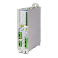
Kollmorgen SERVOSTAR 300 Instruction Manual (142 pages)
Digital Servo Amplifier
Brand:
Kollmorgen
| Category:
Servo Drives
| Size: 19 MB
Table of Contents
Table of Contents
3
1 Table of Contents
9
2 General
9
Using the PDF Format
9
Symbols Used
10
Abbreviations Used
11
3 Safety
12
You Should Pay Attention to this
12
Warning Notes Placed on the Product
14
Use as Directed
15
Prohibited Use
15
4 Product Life Cycle Handling
16
Transport
16
Packaging
16
Storage
16
Installation, Setup and Normal Operation
16
Decommissioning
17
Maintenance and Cleaning
17
Disassembly
17
System Repair
18
Disposal
18
5 Approvals
19
Conformance with Ul/Cul
19
Conformance with CE
20
European Directives and Standards for the Machine Builder
20
Functional Safety Conformance (STO) According to EC Machinery Directive
21
Conformance with Rohs
21
Conformance with REACH
21
Conformance with EAC
21
6 Package
22
Package Supplied
22
Nameplate
22
Part Number Scheme
23
7 Technical Description
24
The SERVOSTAR 300 Family of Digital Servo Amplifiers
24
Technical Data
26
Technical Data 110 / 230 V (Types S3
26
Technical Data 230V
27
Inputs / Outputs, Auxiliary Voltage
28
Connectors
28
Recommended Tightening Torques
28
Fusing
28
Ambient Conditions, Ventilation and Mounting Position
29
Conductor Cross-Sections
29
Motor Holding Brake
30
LED Display
31
Grounding System
31
Dynamic Braking (Brake Circuit)
31
Switch-On and Switch-Off Behavior
33
Behavior in Standard Operation
34
Behavior in the Event of an Error (with Standard Setting)
35
Stop-, Emergency Stop-, Emergency off Function to IEC 60204
36
Stop
36
Emergency Stop
37
Emergency off
37
Safe Torque off (STO)
38
Safety Characteristic Data
38
Safety Notes
39
Use as Directed
40
Prohibited Use STO
40
Technical Data and Pinning
40
Enclosure
40
Wiring
40
Functional Description
41
Safe Operation Sequence
41
Control Circuit
42
Functional Test
43
Mains Supply Circuit
43
Shock-Hazard Protection
44
Leakage Current
44
Residual Current Protective Device (RCD)
44
Isolating Transformers
44
8 Mechanical Installation
45
Important Notes
45
Guide to Mechanical Installation
45
Mounting
46
Dimensions
47
9 Electrical Installation
48
Important Notes
48
Guide to Electrical Installation
49
Wiring
50
Shielding Connection to the Front Panel
51
Technical Data for Cables
52
Components of a Servo System
53
Block Diagram
54
Connector Assignment
55
Connection Overview
56
Voltage Supply
58
Connection to Various Mains Supply Networks
58
Auxiliary Supply (X4)
59
Mains Supply Connection (X0), Three Phase
59
Mains Supply Connection (X0), Two Phase Without Neutral
59
Mains Supply Connection (X0), Single Phase with Neutral
60
DC Bus Link (X8)
61
External Brake Resistor (X8)
61
Capacitor Module KCM (X8)
62
Motor Power and Motor Holding Brake Connection (X9)
64
Feedback Systems
65
Primary and Secondary Feedback Types
66
SFD3 (X1), Single Cable Connection
67
HIPERFACE DSL (X1), Single Cable Connection
68
Resolver (X2)
69
Sine Encoder with Biss Analog (X1)
70
Encoder with Biss Digital (X1)
71
Sine Encoder with Endat 2.1 (X1)
72
Encoder with Endat 2.2 (X1)
73
Sine Encoder with HIPERFACE (X1)
74
Sine Encoder with SSI (X5, X1)
75
Sine Encoder Without Data Channel (X1)
76
Sine Encoder with Hall (X1)
77
ROD (Aquadb) 5V, 1.5Mhz (X1)
78
ROD (Aquadb) 5V, 350Khz (X1)
79
ROD (Aquadb) 5V, 350Khz with Hall (X1)
80
ROD (Aquadb) 5V (X5, X1)
81
ROD (Aquadb) 5V with Hall (X5, X1)
82
ROD (Aquadb) 24V (X3)
83
ROD (Aquadb) 24V with Hall (X3, X1)
84
SSI Encoder (X5, X1)
85
Hall Sensors (X1)
86
Electronic Gearing, Master-Slave Operation
87
Encoder Control Types
87
Connection to Stepper Motor Controllers (Step and Direction)
88
Step / Direction with 5 V Signal Level (X1)
88
Step / Direction with 24 V Signal Level (X3)
88
Step / Direction with 5 V Signal Level (X5)
89
Anschluss für Master-Slave Betrieb
89
Master-Slave 5V (X1)
89
Master-Slave 5V (X5)
89
Encoder Emulation, Position Output
90
Incremental Encoder Output (Aquadb) (X5)
90
SSI Encoder Output (X5)
91
Digital and Analog Inputs and Outputs
92
Analog Inputs (X3)
92
Digital Inputs (X3/X4)
93
Digital Outputs (X3)
94
RS232 Interface, PC Connection (X6)
95
CAN-Bus Interface (X6)
96
10 Setup
97
Important Notes
97
Setup Software
98
Use as Directed
98
Software Description
98
Hardware Requirements, Operating Systems
99
Installation under WINDOWS
99
Quickstart, Initial Drive Test
100
Preparation
100
Connect
102
Important Screen Elements
103
Setup Wizard
104
Basic Setup
104
Units/Mechanical
105
Motor (Rotary) and Feedback
106
Motor (Linear) / Feedback (Encoder)
106
Save Parameters and Restart
107
Motion Service (Jog Mode)
107
More Setup Screens
108
Multi Axis System
109
Keypad Operation and LED Display
109
Operation
110
Status Display
110
Standard Menu Structure
110
Advanced Menu Structure
111
Error Messages
112
Warning Messages
113
Trouble Shooting
114
11 Expansions
115
Guide to Installation of Expansion Cards
115
Expansion Card -I/O-14/08
116
Technical Data
116
Leds
116
Entering a Motion Block Number (Example)
116
Connector Assignments
117
Connection Diagram (Default)
118
Expansion Card -PROFIBUS
119
Connection Technology
119
Connection Diagram
119
Expansion Card -SERCOS
120
Leds
120
Connection Technology
120
Connection Diagram
121
Setup
121
Expansion Card - DEVICENET
122
Connection Technology
122
Connection Diagram
122
Combined Module Status and Network Status LED
123
Setup
123
Bus Cable
124
Expansion Card -SYNQNET
125
NODE ID Switch
125
NODE LED Table
125
Synqnet Connection, Connector X21B / X21C (RJ-45)
125
Digital Inputs and Outputs, Connector X21A (Subd 15-Pin, Socket)
126
Connection Diagram Digital Inputs and Outputs, Connector X21A
126
Expansion Card - FB-2To1
127
Pinout
127
Wiring Example with Biss Digital (Primary) and Sincos (Secondary)
128
Expansion Card -PROFINET
129
Device Master File
129
Led
129
Connection Technology
129
Connection Examples
130
Expansion Module -2CAN
131
Installation
131
Connection Technology
131
Connector Assignments
132
Setup of Station Address and Baud Rate
132
Option "Ethercat
133
NODE LED Table
133
Connection Diagram
133
Option "FAN", Ventilator Control
134
12 Appendix
135
Glossary
135
Kollmorgen SERVOSTAR 300 Instruction Manual (138 pages)
Digital Servo Amplifier
Brand:
Kollmorgen
| Category:
Amplifier
| Size: 4 MB
Table of Contents
Table of Contents
3
1 General
7
About this Manual
7
Notes for the Online Edition (PDF Format)
7
Symboles Used
8
Standards Used
8
Abbreviations Used
9
2 Safety
10
You Should Pay Attention to this
10
Use as Directed
12
Prohibited Use
13
Warning Notes Placed on the Product
13
3 Handling
14
Transport
14
Packaging
14
Storage
14
Handling 3.1 Transport
14
Decommissioning
15
Maintenance and Cleaning
15
Disassemble
15
Repair
16
Disposal
16
4 Approvals
17
Conformance with UL and Cul
17
EC Conformance
18
European Directives and Standards for the Machine Builder
18
Safety Conformance (STO) According to Machine Directive
19
EAC Conformance
19
5 Package
21
Package Supplied
21
Nameplate
21
Package 5.1 Package Supplied
21
Part Number Scheme
22
6 Technical Description
23
The S300 Family of Digital Servo Amplifiers
23
Technical Data
25
Technical Data for 110/230 V (Types S3
25
Technical Data for 400/480 V (Types S3
26
Inputs / Outputs, Auxiliary Voltage
27
Connectors
27
Recommended Tightening Torques
27
Fusing
27
Ambient Conditions, Ventilation, Mounting Position
28
Conductor Cross-Sections
28
Motor Holding Brake
29
LED Display
30
Grounding System
30
Dynamic Braking (Brake Circuit)
30
Switch-On and Switch-Off Behavior
32
Behavior in Standard Operation
33
Behavior in the Event of an Error (with Standard Setting)
34
Stop-, Emergency Stop-, Emergency off Function to IEC 60204
35
Stop
35
Emergency Stop
36
Emergency off
36
Safety Function STO
37
Safety Characteristic Data
37
Safety Notes
38
Use as Directed
39
Prohibited Use
39
Technical Data and Pinning
39
Enclosure
39
Wiring
39
Functional Description
40
Control Circuit
42
Shock-Hazard Protection
44
Leakage Current
44
Residual Current Protective Device (RCD)
44
Isolating Transformers
44
7 Mechanical Installation
45
Important Notes
45
Guide to Mechanical Installation
45
Assembly
46
Dimensions
47
8 Electrical Installation
49
Important Notes
49
Guide to Electrical Installation
50
Wiring
51
Shielding Connection to the Front Panel
52
Technical Data for Connecting Cables
53
Components of a Servo System
54
Block Diagram
55
Connector Assignments
56
Connection Diagram (Overview)
57
Electrical Supply
58
Connection to Various Mains Supply Networks
58
Auxiliary Supply (X4)
59
Mains Supply Connection (X0), Three Phase
59
Mains Supply Connection (X0), Two Phase Without Neutral
59
Mains Supply Connection (X0), Single Phase with Neutral
60
DC Bus Link (X8)
61
External Brake Resistor (X8)
61
Capacitor Modules KCM (X8)
62
Motor Connection with Brake (X9)
64
Feedback Systems
65
Primary and Secondary Feedback Types
66
SFD3 (X1), Single Cable Connection
67
HIPERFACE DSL (X1), Single Cable Connection
68
Resolver (X2)
69
Sine Encoder with Biss Analog (X1)
70
Sine Encoder with Biss Digital (X1)
71
Sine Encoder with Endat 2.1 (X1)
72
Sine Encoder with Endat 2.2 (X1)
73
Sine Encoder with HIPERFACE (X1)
74
Sine Encoder with SSI (X5, X1)
75
Sine Encoder Without Data Channel (X1)
76
Sine Encoder with Hall (X1)
77
ROD (Aquadb) 5V, 1.5 Mhz (X1)
78
ROD (Aquadb) 5V, 350 Khz (X1)
79
ROD (Aquadb) 5V with Hall (X1)
80
ROD (Aquadb) 5V (X5)
81
ROD (Aquadb) 5V with Hall (X5, X1)
82
ROD (Aquadb) 24V (X3)
83
ROD (Aquadb) 24V with Hall (X3, X1)
84
SSI Encoder (X5, X1)
85
Hall Sensors (X1)
86
Electronic Gearing, Master-Slave Operation
87
Signal Source
87
Connection to Stepper Motor Controllers (Step and Direction)
88
Master-Slave Connection
89
Encoder Emulation
90
Incremental Encoder Output - a Quad B (X5)
90
SSI Encoder Output (X5)
91
Digital and Analog Inputs and Outputs
92
Analog Inputs (X3)
92
Digital Inputs (X3/X4)
93
Digital Outputs (X3)
94
RS232 Interface, PC Connection (X6)
95
Canopen Interface (X6)
96
9 Setup
97
Important Notes
97
Setup Software
98
Use as Directed
98
Software Description
98
Hardware Requirements
99
Operating Systems
99
Installation under WINDOWS
99
Quickstart
100
Preparation
100
Connect
102
Important Screen Elements
103
Setup Wizard
104
Motion Service (Jog Mode)
107
More Setup Screens
108
Multi-Axis System
109
Station Address for CAN-Bus
109
Baud Rate for CAN-Bus
109
Keypad Operation / LED Display
109
Keypad Operation
110
Status Display
110
Standard Menu
110
Advanced Menu
111
Error Messages
112
Warning Messages
113
Trouble Shooting
114
10 Expansions Cards
115
Guide to Installation of Expansion Cards
115
Expansion Card -I/O-14/08
116
Technical Data
116
Leds
116
Entering a Motion Block Number (Example)
116
Connector Assignments
117
Connection Diagram (Default)
118
Expansion Card -PROFIBUS
119
Connection Technology
119
Connection Diagram
119
Expansion Card -SERCOS
120
Leds
120
Connection Technology
120
Connection Diagram
121
Modifying the Station Address
121
Modifying the Baud Rate and Optical Power
121
Expansion Card -DEVICENET
122
Connection Technology
122
Connection Diagram
122
Combined Module/Network Status-LED
123
Setting the Station Address (Device Address)
123
Setting the Transmission Speed
123
Bus Cable
124
Expansion Card -SYNQNET
125
NODE ID Switch
125
Node LED Table
125
Synqnet Connection, Connector X21B/C (RJ-45)
125
Digital Inputs/Outputs, Connector X21A (Subd 15-Pin, Socket)
126
Connection Diagram Digital Inputs/Outputs, Connector X21A
126
Expansion Card - FB-2To1
127
Pinout
127
Wiring Example with Biss Digital (Primary) and Sincos (Secondary)
128
Expansion Module -2CAN
129
Installation
129
Connection Technology
129
Connector Assignments
130
Connection Diagram
130
Option "Ethercat
131
Node LED Table
131
Connection Diagram
131
Option "FAN", Ventilator Control
132
11 Appendix
133
Glossary
133
Order Codes
135
Index
136
Advertisement
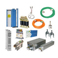
Kollmorgen SERVOSTAR 300 Manual (88 pages)
Brand:
Kollmorgen
| Category:
Amplifier
| Size: 5 MB
Table of Contents
1 Table of Contents
3
2 General
7
About this Manual
7
Hints for the Online Edition (PDF Format)
7
Safety Notes
8
Symbols Used
8
You Should Pay Attention to this
9
3 Digital Drive Systems
10
Drive System with S300
10
Drive System with S400
11
Drive System with S601
12
Drive System with S640
13
Drive System with S701
14
Drive System with S748/772
15
Drive System with AKD-X00306
16
Drive System with AKD-X00307
17
Drive System with AKD-X04807
18
Decentralized Drive System with AKD-C and AKD-N
19
4 Mechanical Accessories
20
Mounting Kit for AKMH Motors
20
Suspension Unit for AKM Motors
20
Fan Kit for AKM7 Motors
21
Mechanical Accessories for AKD-N and AKD-C
22
Heat Sink for AKD-N
22
Mounting Clamps for AKD-N
22
Sealing Plugs for AKD-N Connectors
23
Connector Kit for AKD-C
23
Cabinet Connector Coupling for AKD-C/N
23
5 Shield Clamps
24
Auxiliary Terminals on the Servo Amplifier
24
External Shielding Busbar
25
6 Mains Chokes
26
General
26
Important Notes
26
Type Assignment and Order Codes
26
Mains Choke 3L
27
7 Mains Filters
28
General
28
Important Notes
28
Type Assignment and Order Codes
28
Mains Filters 1NF-10
29
Mains Filters 1NF-20B, 1NF-25
30
Mains Filters 3NF-07
30
Mains Filters 3EF-42
32
8 Brake Resistors
33
General
33
Important Notes
33
Type Assignment and Order Codes
34
External Brake Resistor BAFP(U)
35
External Brake Resistor BAR(U)
36
External Brake Resistor BAS(U)
37
9 Capacitor Modules
38
General
38
Important Notes
38
Type Assignment and Order Codes
39
Example Installation with AKD-P, KCM-P and KCM-E
39
KCM Module
40
10 Motor Chokes
41
General
41
Important Notes
42
Type Assignment and Order Codes
42
Motor Choke 3YL-24
43
Motor Choke 3YLN-XX
44
11 Cables
45
Technical Data for Cables
45
Tools
45
PC Connection
46
Akd
46
S300, S400, S600, S700
46
Power Voltage Supply, External Brake Resistor, DC Bus Link
48
Mating Connector (Part of Delivery)
48
Mating Connector (Optional)
48
Recommended Cable Type
49
Preparing Cables for AKD/S300/S400/S601
49
Preparing Cables for S640/670 and S748/772
51
Auxiliary Voltage Supply
52
Mating Connector (Part of Delivery)
52
Recommended Cable Type
52
Preparing Cables
53
Digital/Analog Inputs/Outputs
54
Digital In/Outputs for AKD-C
54
Digital In/Outputs for AKD-N
54
Digital/Analog I/O for S300/S400/S600/S700 and AKD-B/P/T/M
55
Preparing Cables
56
Encoder Emulation, Stepper Motor Control, Master-Slave
57
Mating Connector, Cable Type
57
Connection
57
Termination Resistors
57
Preparing Cables
58
Kollmorgen | December
58
Ethernet Cable
59
Order Codes Ethernet Cable, Configured
59
CAN Bus Cable
60
CAN Bus Cable AKD
60
Can Bus Cable for S300/S400/S600/S700
60
Hybrid Cables
62
AKD to AKM1 Motor (I-Tec Connector)
62
AKD to AKM2-6 (IP65 Connector)
63
AKD-C to AKD-N in the Decentralized Drive System
65
AKD-N to AKD-N in the Decentralized Drive System
65
Motor Cables
66
General
66
Motor Cables, Configured
66
Order Codes Motor Cables for S300
67
Order Codes Motor Cables for S400
67
Order Codes Motor Cables for S601
68
Order Codes Motor Cables for S701-712
69
Order Codes Motor Cables for S724
70
Order Codes Motor Cables for S748, S640/670
70
Order Codes Motor Cables for AKD-B/P/T/M
72
Order Codes Motor Cables for AKD-N
74
Preparing Motor Cables (Motor End)
75
Motor Series AKM2
75
Motor Series AKM8, DBL7/8
75
Preparing Motor Cables (Servo Amplifier End)
77
Preparing Cables for S300/S400
77
Preparing Cables for S601
78
Preparing Cables for S701
79
Preparing Cables for AKD-X00306/X00606
79
Preparing Cables for AKD-X01206/X02406/X0Xx07
80
Preparing Cables for S640/670 and S748/772
80
Feedback Cables
82
Resolver Cables
82
Resolver Cables for S300/S400/S600/S700
82
Resolver Cable for AKD
83
SFD Cables for AKD
83
Encoder Cables
84
Encoder Cables for S300/S400/S600/S700
84
Encoder Cables for AKD
85
Comcoder Cables
86
Comcoder Cables for S300/S400/S600/S700
86
Comcoder Cables for AKD
87
Advertisement
Related Products
Kollmorgen SERVOSTAR 303
Kollmorgen SERVOSTAR 306
Kollmorgen SERVOSTAR 310
Kollmorgen SERVOSTAR 341
Kollmorgen SERVOSTAR 343
Kollmorgen SERVOSTAR 346
Kollmorgen SERVOSTAR 670
Kollmorgen SERVOSTAR 640
Kollmorgen SERVOSTAR 601
Kollmorgen SERVOSTAR 620
Kollmorgen Categories
Servo Drives
Amplifier
Touch terminals
DC Drives
Engine
More Kollmorgen Manuals
Login
Sign In
OR
Sign in with Facebook
Sign in with Google
Upload manual
Upload from disk
Upload from URL