Kollmorgen SERVOSTAR 300 Instruction Manual
Digital servo amplifier
Hide thumbs
Also See for SERVOSTAR 300:
- Manual (88 pages) ,
- Instruction manual (138 pages) ,
- Safety manual (154 pages)
Table of Contents

Related Manuals for Kollmorgen SERVOSTAR 300


Summary of Contents for Kollmorgen SERVOSTAR 300
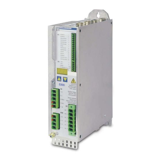
- Page 1 SERVOSTAR 300 Digital Servo Amplifier S300 Instructions Manual Edition: May 2020 Translation of the original instructions. Valid for Hardware Revision 04.20 For safe and proper use, follow these instructions. Keep them for future reference.
- Page 2 Technical changes which improve the performance of the device may be made without prior notice! This document is the intellectual property of Kollmorgen. All rights reserved. No part of this work may be reproduced in any form (by photocopying, microfilm or any other method) or stored, processed, copied or distributed by electronic means without the written permission of Kollmorgen.
-
Page 3: Table Of Contents
6.2 Nameplate 6.3 Part Number Scheme 7 Technical description 7.1 The SERVOSTAR 300 family of digital servo amplifiers 7.2 Technical Data 7.2.1 Technical Data 110 / 230 V (Types S3_ _6_) 7.2.2 Technical Data 230V ... 480 V (types S3_ _0_) 7.2.3 Inputs / outputs, Auxiliary voltage... - Page 4 9.12 Primary and secondary feedback types 9.12.1 SFD3 (X1), single cable connection 9.12.2 HIPERFACE DSL (X1), single cable connection 9.12.3 Resolver (X2) 9.12.4 Sine Encoder with BiSS analog (X1) 9.12.5 Encoder with BiSS digital (X1) Kollmorgen | kdn.kollmorgen.com | May 2020...
- Page 5 10.3.4.3 Motor (rotary) and Feedback 10.3.4.4 Motor (linear) / Feedback (Encoder) 10.3.4.5 Save Parameters and Restart 10.3.5 Motion Service (Jog Mode) 10.3.6 More Setup Screens 10.4 Multi axis system 10.5 Keypad operation and LED display Kollmorgen | kdn.kollmorgen.com | May 2020...
- Page 6 11.9.1 Installation 11.9.2 Connection technology 11.9.3 Connector assignments 11.9.4 Setup of Station Address and Baud Rate 11.10 Option "EtherCAT" 11.10.1 NODE LED table 11.10.2 Connection diagram 11.11 Option "FAN", ventilator control 12 Appendix 12.1 Glossary Kollmorgen | kdn.kollmorgen.com | May 2020...
- Page 7 S300 Instructions Manual | Table of Contents 12.2 Order codes 13 Index 14 Record of document revisions Kollmorgen | kdn.kollmorgen.com | May 2020...
- Page 8 S300 Instructions Manual | --- / --- Kollmorgen | kdn.kollmorgen.com | May 2020...
-
Page 9: Table Of Contents
S300 Instructions Manual | 2 General 2 General 2.1 General This manual describes the digital servo amplifiers of the SERVOSTAR 300 (S300, standard version, 1.5 to 10 A nominal current). A more detailed description of the expansion cards that are currently available and the digital... -
Page 10: Symbols Used
Warning of danger from suspended loads. Warning of danger from automatic start. Drawing symbols Symbol Description Symbol Description Signal ground Diode Chassis ground Relay Protective earth Relay switch off delayed Resistor Normally open contact Fuse Normally closed contact Kollmorgen | kdn.kollmorgen.com | May 2020... -
Page 11: Abbreviations Used
Internal brake resistor Resolver A quad B encoder Safety Integrity Level SIL CL Safety Integrity Level Claim Limit SRAM Static RAM Synchronous serial interface Safe Torque Off V AC AC voltage V DC DC voltage Kollmorgen | kdn.kollmorgen.com | May 2020... -
Page 12: Safety
The manufacturer of the machine must generate a risk assessment for the machine, and take appropriate measures to ensure that unforeseen movements cannot cause injury or damage to any person or property. Additional requirements on specialist staff may also result from the risk assessment. Kollmorgen | kdn.kollmorgen.com | May 2020... - Page 13 Thermal sensors, motor holding brakes and feedback systems built into the connected motor must have reinforced insulation (according to IEC61800-5-1) against system components with power voltage, according to the required application test voltage. All Kollmorgen com- ponents meet these requirements.
-
Page 14: Warning Notes Placed On The Product
S300 Instructions Manual | 3 Safety 3.2 Warning notes placed on the product Residual Voltage. Wait 5 minutes after removing power. If these signs are damaged, they must be replaced immediately. Kollmorgen | kdn.kollmorgen.com | May 2020... -
Page 15: Use As Directed
2000V. Motors The SERVOSTAR 300 family of servo amplifiers is only intended to drive specific brush- less synchronous servomotors, with closed-loop control of torque, speed and/or position. The rated voltage of the motors must be at least as high as the DC bus link voltage of the servo amplifier. -
Page 16: Product Life Cycle Handling
S300 Instructions Manual | 4 Product life cycle handling 4 Product life cycle handling 4.1 Transport Transport the SERVOSTAR 300 in accordance with IEC 61800-2 as follows: Only by qualified personnel in the manufacturer’s original recyclable packaging Avoid shocks Temperature: –25 to +70°C, max. 20K/hr rate of change, class 2K3 acc. -
Page 17: Decommissioning
80 °C (176 °F). Before touching the device, check the temperature and wait until it has cooled below 40 °C (104 °F). 3. Remove the connectors. Disconnect the potential earth connection last. 4. Demount: loosen the fastening screws. Remove the device. Kollmorgen | kdn.kollmorgen.com | May 2020... -
Page 18: System Repair
In accordance with the WEEE-2012/19/EU guideline and similar, the manufacturer accepts returns of old devices and accessories for professional disposal. Transport costs are the responsibility of the sender. Contact Kollmorgen and clarify the logistics. Kollmorgen | kdn.kollmorgen.com | May 2020... -
Page 19: Approvals
AC input side based on the max. peuvent être groupés d'entrée AC basé sur input fuse (e.g. 3xS346 with one com- le max. fusible d’entrée (par exemple mon 6A fuse in line). 3xS346 avec un fusible de 6A commune). Kollmorgen | kdn.kollmorgen.com | May 2020... -
Page 20: Conformance With Ce
Kollmorgen declares the conformity of the products SERVOSTAR 300 (S300) with the fol- lowing directives EC Machinery Directive 2006/42/EU... -
Page 21: Functional Safety Conformance (Sto) According To Ec Machinery Directive
Customs Union (Russia, Belarus, Kazakhstan) similar to the European CE mark. Kollmorgen declares, that the device has passed all required conformity procedures in a mem- ber state of the Eurasian Customs Union, and that the device meets all technical require-... -
Page 22: Package
S300 Instructions Manual | 6 Package 6 Package 6.1 Package Supplied When you order a SERVOSTAR 300 series amplifier (Order codes (➜ # 137)), you will receive: S3xx Mating connectors X0, X3, X4, X8 Mating Connector X9 (with SERVOSTAR 303-310 only ) (S3xx6) -
Page 23: Part Number Scheme
Expansions and device options cannot be combined. Comparison device name -> part number Device Name Part Number SERVOSTAR 303 S30361-NA SERVOSTAR 306 S30661-NA SERVOSTAR 310 S31061-NA SERVOSTAR 341 S30101-NA SERVOSTAR 343 S30301-NA SERVOSTAR 346 S30601-NA Kollmorgen | kdn.kollmorgen.com | May 2020... -
Page 24: Technical Description
S300 Instructions Manual | 7 Technical description 7 Technical description 7.1 The SERVOSTAR 300 family of digital servo amplifiers Standard version Two voltage classes with large nominal voltage range +10% 1 x 110 V … 3 x 230 V (SERVOSTAR 303-310, S3xx6) - Page 25 FB-2to1 expansion card,, (➜ # 127) PROFINET expansion card, (➜ # 129) -2CAN- expansion module, separated connectors for CAN-bus and RS232, (➜ # 131) Several third-party expansion cards (ModBus, LightBus, FIP-IO etc. please contact the manufacturer for further information) Kollmorgen | kdn.kollmorgen.com | May 2020...
-
Page 26: Technical Data
Height without connectors Width Depth without/with connectors 171 / <200 *in single-phase applications nom./peak current is limited to value below nominal value. This depends on motor constant Kt and motor speed (➜ # 60). Kollmorgen | kdn.kollmorgen.com | May 2020... -
Page 27: Technical Data 230V
Residual voltage drop at rated current Quiescent dissipation, output stage disabled Dissipation at rated current (incl. power supply losses, without brake dissipation) Noise emission max. dB(A) Mechanical Weight Height without connectors Width Depth without/with connectors 171 / <230 Kollmorgen | kdn.kollmorgen.com | May 2020... -
Page 28: Inputs / Outputs, Auxiliary Voltage
24V supply F max. 8 A H1/2/3 Brake resistor F 6 A* 6 A* B1/2 European fuses: gRL or gL 400V/500V, T means time-delay, US fuses: class RK5/CC/J/T, 600VAC 200kA, time-delay * for example Bussmann FWP-xx Kollmorgen | kdn.kollmorgen.com | May 2020... -
Page 29: Ambient Conditions, Ventilation And Mounting Position
For multi-axis systems, observe the specific operating conditions for your system. To reach the max. permitted cable length, observe cable requirements (➜ # 52). * Kollmorgen North America supplies cables up to 39 meters, Europe up to max. length Kollmorgen | kdn.kollmorgen.com | May 2020... -
Page 30: Motor Holding Brake
(see motor manual), the matching data are loaded from the motor database when the motor is selected. A description of the interface can be found on page (➜ # 64). Kollmorgen | kdn.kollmorgen.com | May 2020... -
Page 31: Led Display
1. (above) for the amplifier that has the low- est switch-off threshold (resulting from tolerances). Technical data of the brake circuits dependent on the amplifiers type and the mains voltage situation see table on the next page. Kollmorgen | kdn.kollmorgen.com | May 2020... - Page 32 Max. brake power (average for 1s) 0,91 0,86 0,85 Pulse brake power External brake resistor (RBext), optional Continuous power for external resistor (RBext) Suitable external brake resistors can be found in our accessories manual. Kollmorgen | kdn.kollmorgen.com | May 2020...
-
Page 33: Switch-On And Switch-Off Behavior
The chapter “Safety function STO” describes how to use the STO function. See (➜ # 38) onwards. Kollmorgen | kdn.kollmorgen.com | May 2020... -
Page 34: Behavior In Standard Operation
(➜ # 30). The built-in safety function STO can be used to switch off the drive, so that functional safety is ensured at the drive shaft (➜ # 38) . Kollmorgen | kdn.kollmorgen.com | May 2020... -
Page 35: Behavior In The Event Of An Error (With Standard Setting)
Even if there is no intervention from an external control system (in the example, the ENABLE signal remains active), the motor is immediately braked using the emergency stop ramp if the error is detected and assuming that no changes have been made to the factory setting (ACTFAULT=1). Kollmorgen | kdn.kollmorgen.com | May 2020... -
Page 36: Stop-, Emergency Stop-, Emergency Off Function To Iec 60204
If applicable, the Stop function must signal its status to the control logic. A reset of the Stop function must not create a hazardous situation. Examples for implementation can be found in the KDN on page Stop and Emergency Stop Function. Kollmorgen | kdn.kollmorgen.com | May 2020... -
Page 37: Emergency Stop
This results in a category 0 stop. If this stop category is not possible in the applic- ation, then the Emergency Off function must be replaced by other measures (for example by protection against direct touching). Kollmorgen | kdn.kollmorgen.com | May 2020... -
Page 38: Safe Torque Off (Sto)
The subsystems (servo amplifiers) are totally described for safety technics with the char- acteristic data SIL CL, PFHD and TM. Device Operation Mode EN 13849-1 EN 62061 [Years] [1/h] STO-Enable single channel PL d, Cat. 3 SIL CL 2 1,50E-07 Kollmorgen | kdn.kollmorgen.com | May 2020... -
Page 39: Safety Notes
1. Brake the drive in a controlled manner (velocity setpoint = 0V) 2. When speed = 0 rpm, disable the servo amplifier (enable = 0V) 3. If there is a suspended load, block the drive mechanically 4. Activate STO. Kollmorgen | kdn.kollmorgen.com | May 2020... -
Page 40: Use As Directed
(firmly), protected from outside damage (e.g. laying in a cable duct), in different sheathed cables or protected individually by grounding connection. Wiring remaining within the demanded enclosure must meet the requirements of the standard IEC 60204-1. Kollmorgen | kdn.kollmorgen.com | May 2020... -
Page 41: Functional Description
3. If there is a suspended load, block the drive mechanically 4. Activate STO (STO-Enable = 0V) The diagram shows how STO should be used to ensure a safe stop of the drive and error free operation of the servo amplifier. Kollmorgen | kdn.kollmorgen.com | May 2020... -
Page 42: Control Circuit
Pilz. The use of safety switch gears of other manufacturers is possible, if these also fulfill the SIL CL 2 according to IEC 62061 and PL d according to ISO 13849-1. Consider the wiring instructions (➜ # 40). Kollmorgen | kdn.kollmorgen.com | May 2020... -
Page 43: Functional Test
1. Stop all drives, with setpoint 0V, disable servo amplifier (Enable=0V). 2. Activate STO e.g. by opening protective screen (voltage at X4/5 = 0V). Correct behavior: the servo amplifier displays -S-. 7.9.8.4 Mains supply circuit Kollmorgen | kdn.kollmorgen.com | May 2020... -
Page 44: Shock-Hazard Protection
50 to 300 mA Protection against "indirect contact" for stationary equipment Recommendation: In order to protect against direct contact (with motor cables shorter than 5 m) Kollmorgen recommends that each drive be protected individually using a 30 mA RCD which is sensitive to all currents. -
Page 45: Mechanical Installation
Grounding EMC-compliant (EMI) shielding and grounding see (➜ # 56). Shielding Earth (ground) the mounting plate, motor housing and CNC-GND of the con- trols. Notes for wiring technology (➜ # 51) Kollmorgen | kdn.kollmorgen.com | May 2020... -
Page 46: Mounting
S300 Instructions Manual | 8 Mechanical Installation 8.3 Mounting Material: 3 hexagon socket screws to EN 4762, M5 Tool required: 4 mm Allen key Kollmorgen | kdn.kollmorgen.com | May 2020... -
Page 47: Dimensions
S300 Instructions Manual | 8 Mechanical Installation 8.4 Dimensions Kollmorgen | kdn.kollmorgen.com | May 2020... -
Page 48: Electrical Installation
The servo amplifier's status must be monitored by the PLC to acknowledge critical situ- ations. Wire the BTB/RTO contact in series into the emergency off circuit of the installation. The emergency off circuit must operate the supply contactor. Kollmorgen | kdn.kollmorgen.com | May 2020... -
Page 49: Guide To Electrical Installation
Connect main power supply (for max. permissible voltage values (➜ # 29)) Connect PC (➜ # 95). Final check Final check of the implementation of the wiring, according to the wiring dia- grams which have been used. Kollmorgen | kdn.kollmorgen.com | May 2020... -
Page 50: Wiring
(➜ # 116) PROFIBUS: (➜ # 119) sercos® II: (➜ # 120) DeviceNet: (➜ # 122) SynqNet: (➜ # 125) FB-2to1: (➜ # 127) -2CAN-: (➜ # 131) Options: EtherCAT (➜ # 133) (➜ # 134) Kollmorgen | kdn.kollmorgen.com | May 2020... -
Page 51: Shielding Connection To The Front Panel
Use the shield clamp that is delivered with the motor cable for the shield connection of the motor cable. The clamp must be hooked in the lower shroud and guar- antees optimal contact between shield and shroud. Kollmorgen | kdn.kollmorgen.com | May 2020... -
Page 52: Technical Data For Cables
Feedback cable less than 120 pF/m Example Motor cable: Technical data For a detailed description of Kollmorgen cable types and how to assemble them, please refer to the accessories manual. Chokes Motor cables longer than 25m require the use of a motor choke 3YL or 3YLN. -
Page 53: Components Of A Servo System
Cables drawn bold are shielded. Electrical ground is drawn with dash-dotted lines. Optional devices are connected with dashed lines to the servo amplifier. The required accessories are described in our accessories manual. STO function is deactivated in the example. Kollmorgen | kdn.kollmorgen.com | May 2020... -
Page 54: Block Diagram
S300 Instructions Manual | 9 Electrical Installation 9.5 Block diagram The block diagram below just provides an overview. Kollmorgen | kdn.kollmorgen.com | May 2020... -
Page 55: Connector Assignment
S300 Instructions Manual | 9 Electrical Installation 9.6 Connector assignment Kollmorgen | kdn.kollmorgen.com | May 2020... -
Page 56: Connection Overview
S300 Instructions Manual | 9 Electrical Installation 9.7 Connection overview Refer to the Safety Instructions (➜ # 12) and Use as Directed (➜ # 15) ! "Single Cable" Kollmorgen | kdn.kollmorgen.com | May 2020... - Page 57 S300 Instructions Manual | 9 Electrical Installation "Dual Cable" Kollmorgen | kdn.kollmorgen.com | May 2020...
-
Page 58: Voltage Supply
9.8.1 Connection to various mains supply networks An isolating transformer is required for 400V to 480V networks that are asymmetrically grounded or not grounded as shown below. * Order code reference see (➜ # 137) Kollmorgen | kdn.kollmorgen.com | May 2020... -
Page 59: Auxiliary Supply (X4)
9.8.3 Mains supply connection (X0), three phase Directly to 3-phase supply network, filter is integrated Fusing (e.g. fusible cut-outs) to be provided by the user (➜ # 28) 9.8.4 Mains supply connection (X0), two phase without neutral Kollmorgen | kdn.kollmorgen.com | May 2020... -
Page 60: Mains Supply Connection (X0), Single Phase With Neutral
Speed can be limited with the ASCII parameter VLIM to reach the necessary current for the required torque. With a special motor type (kT = constant depending on the motor type) the possible output current depending on speed is similar to the diagram below: Kollmorgen | kdn.kollmorgen.com | May 2020... -
Page 61: Dc Bus Link (X8)
Fusing information are explained in detail in the KDN on page "DC Bus link in parallel". 9.9.1 External brake resistor (X8) Remove the plug-in link between the terminals X8/5 (-RB) and X8/4 (+Rbint). Fusing (➜ # 28). Kollmorgen | kdn.kollmorgen.com | May 2020... -
Page 62: Capacitor Module Kcm (X8)
S300 Instructions Manual | 9 Electrical Installation 9.9.2 Capacitor Module KCM (X8) The KCM modules (KOLLMORGEN Capacitor Module) absorb energy generated by the motor when it is operating in generator mode. Normally, this energy is dissipated as waste via brake resistors. KCM modules, however, feed the energy they have stored back into the DC Bus link as and when it is required. - Page 63 (this only applies to the power supply voltage; battery-back the 24 V supply separately). Kollmorgen | kdn.kollmorgen.com | May 2020...
-
Page 64: Motor Power And Motor Holding Brake Connection (X9)
With long motor cables leakage currents endanger the output stage of the servo amplifier. For cable lengths above 25m up to max. 50m, the motor choke 3YL or 3YLN (see accessor- ies manual) must be wired into the motor cable, close to the amplifier. Kollmorgen | kdn.kollmorgen.com | May 2020... -
Page 65: Feedback Systems
GEARMODE Screen page ELECTRONIC GEARING, encoder control (➜ # 87) in the setup software. Scaling and other settings must always be made here. For a detailed description of the ASCII parameters, please refer to the DRIVEGUI.EXE Online-Help. Some possible configurations Kollmorgen | kdn.kollmorgen.com | May 2020... -
Page 66: Primary And Secondary Feedback Types
* * ROD is an abbreviation for “incremental encoder”. 1) Switch on the encoder supply voltage on X1: set ENCVON to 1 2) BiSS C support for Renishaw encoders, Hengstler encoders are not supported. Kollmorgen | kdn.kollmorgen.com | May 2020... -
Page 67: Sfd3 (X1), Single Cable Connection
S300 Instructions Manual | 9 Electrical Installation 9.12.1 SFD3 (X1), single cable connection Connection of the Kollmorgen feedback system SFD3 (primary, (➜ # 65)). SFD3 can be used only with the special Kollmorgen hybrid cable (CCJ9 or WCJ9 type, see Accessories Manual) (on request). -
Page 68: Hiperface Dsl (X1), Single Cable Connection
9.12.2 HIPERFACE DSL (X1), single cable connection Connection of HIPERFACE DSL feedback (primary, (➜ # 65)). HIPERFACE DSL can be used only with the special Kollmorgen hybrid cable (CCJ9 or WCJ9 type, see Accessories Manual) (on request). Maximum cable length 25 m. -
Page 69: Resolver (X2)
X2 and evaluated there. If cable lengths of more than 100 m are planned, please consult our customer service. FBTYPE: 0 The pin assignment shown on the motor side relates to the AKM motors (connector code D). Kollmorgen | kdn.kollmorgen.com | May 2020... -
Page 70: Sine Encoder With Biss Analog (X1)
Frequency limit (sin, cos): 350 kHz Type FBTYPE EXTPOS GEARMODE 5V analog (BiSS B) 5V +/-5% 12V analog (BiSS B) 7.5...11V The pin assignment shown on the motor side relates to the AKM motors. Kollmorgen | kdn.kollmorgen.com | May 2020... -
Page 71: Encoder With Biss Digital (X1)
FBTYPE EXTPOS GEARMODE 5V digital (BiSS B) 5V +/-5% 12V digital (BiSS B) 7,5...11V 5V digital (BiSS C, Renishaw) 5V +/-5% The pin assignment shown on the motor side relates to the AKM motors. Kollmorgen | kdn.kollmorgen.com | May 2020... -
Page 72: Sine Encoder With Endat 2.1 (X1)
50 m are planned, please consult our customer service. Frequency limit (sin, cos): 350 kHz Type FBTYPE EXTPOS GEARMODE ENDAT 2.1 ENDAT 2.1 + Wake&Shake The pin assignment shown on the motor side relates to the AKM motors. Kollmorgen | kdn.kollmorgen.com | May 2020... -
Page 73: Encoder With Endat 2.2 (X1)
If cable lengths of more than 50 m are planned, please consult our customer service. Frequency limit: 1,5MHz Type FBTYPE EXTPOS GEARMODE 5V ENDAT 2.2 5V +/-5% 12V ENDAT 2.2 7,5...11V The pin assignment shown on the motor side relates to the AKM motors. Kollmorgen | kdn.kollmorgen.com | May 2020... -
Page 74: Sine Encoder With Hiperface (X1)
If cable lengths of more than 50 m are planned, please consult our customer service. Frequency limit (sin, cos): 350 kHz Type FBTYPE EXTPOS GEARMODE HIPERFACE The pin assignment shown on the motor side relates to the AKM motors. Kollmorgen | kdn.kollmorgen.com | May 2020... -
Page 75: Sine Encoder With Ssi (X5, X1)
50m are planned, please consult our customer service. Frequency limit (sin, cos): 350 kHz Type FBTYPE EXTPOS GEARMODE SinCos SSI 5V linear Switch on supply voltage for the encoder at X1: set ENCVON to 1 Kollmorgen | kdn.kollmorgen.com | May 2020... -
Page 76: Sine Encoder Without Data Channel (X1)
350 kHz Type FBTYPE EXTPOS GEARMODE Remarks SinCos 5V 5V +/-5% MPHASE from EEPROM SinCos 12V 7.5...11V MPHASE from EEPROM SinCos 5V 5V +/-5% MPHASE wake & shake SinCos 12V 7.5...11V MPHASE wake & shake Kollmorgen | kdn.kollmorgen.com | May 2020... -
Page 77: Sine Encoder With Hall (X1)
All signals are connected to X1 and evaluated there. If cable lengths of more than 25 m are planned, please consult our customer service. Frequency limit (sin, cos): 350 kHz Type FBTYPE EXTPOS GEARMODE SinCos 5V mit Hall 5V +/-5% SinCos 12V mit Hall 7.5...11V Kollmorgen | kdn.kollmorgen.com | May 2020... -
Page 78: Rod (Aquadb) 5V, 1.5Mhz (X1)
If cable lengths of more than 50 m are planned, please consult our customer service. Frequency limit (A, B): 1,5MHz Type FBTYPE EXTPOS GEARMODE Remarks AquadB 5V MPHASE from EEPROM AquadB 5V MPHASE with wake & shake Kollmorgen | kdn.kollmorgen.com | May 2020... -
Page 79: Rod (Aquadb) 5V, 350Khz (X1)
Frequency limit (A, B): 350 kHz Type FBTYPE EXTPOS GEARMODE Remarks AquadB 5V MPHASE from EEPROM AquadB 5V MPHASE with wake & shake The pin assignment shown on the motor side relates to the AKM motors. Kollmorgen | kdn.kollmorgen.com | May 2020... -
Page 80: Rod (Aquadb) 5V, 350Khz With Hall (X1)
(➜ # 77), but the amplifier's pinout is identical to the wiring diagram shown below. Frequency limit (A,B): 350 kHz Type FBTYPE EXTPOS GEARMODE AquadB 5V + Hall The pin assignment shown on the motor side relates to the AKM motors. Kollmorgen | kdn.kollmorgen.com | May 2020... -
Page 81: Rod (Aquadb) 5V (X5, X1)
Frequency limit (A, B, N): 1.5 MHz Type FBTYPE EXTPOS/Gearmode ENCMODE Remarks AquadB 5V MPHASE EEPROM AquadB 5V MPHASE wake&shake Switch on supply voltage for the encoder at X1: set ENCVON to 1. Kollmorgen | kdn.kollmorgen.com | May 2020... -
Page 82: Rod (Aquadb) 5V With Hall (X5, X1)
Voltage supply and the thermal control in the motor is connected to X1. If cable lengths of more than 25 m are planned, please consult our customer service. Frequency limit X5: 1.5 MHz, X1: 350 kHz Type FBTYPE EXTPOS GEARMODE AquadB 5V with Hall Kollmorgen | kdn.kollmorgen.com | May 2020... -
Page 83: Rod (Aquadb) 24V (X3)
The thermal control in the motor is connected to X1 or X2. If cable lengths of more than 25 m are planned, please consult our customer service. Frequency limit: 100 kHz, transition time tv ≤ 0.1μs Type FBTYPE EXTPOS GEARMODE Remarks AquadB 24V MPHASE from EEPROM AquadB 24V MPHASE with wake & shake Kollmorgen | kdn.kollmorgen.com | May 2020... -
Page 84: Rod (Aquadb) 24V With Hall (X3, X1)
The thermal control in the motor is connected to X1 and evaluated there. If cable lengths of more than 25 m are planned, please consult our customer service. Frequency limit X3: 100 kHz, X1: 350 kHz Type FBTYPE EXTPOS GEARMODE AquadB 24V + Hall Kollmorgen | kdn.kollmorgen.com | May 2020... -
Page 85: Ssi Encoder (X5, X1)
The thermal control in the motor is connected to X1 and evaluated there. If cable lengths of more than 50m are planned, please consult our customer service. Frequency limit:: 1.5MHz Type FBTYPE EXTPOS GEARMODE Switch on supply voltage for the encoder at X1: set ENCVON to 1. Kollmorgen | kdn.kollmorgen.com | May 2020... -
Page 86: Hall Sensors (X1)
The thermal control in the motor is connected to X1 and evaluated there. If cable lengths of more than 25 m are planned, please consult our customer service. Frequency limit: 350 kHz Type FBTYPE EXTPOS GEARMODE Hall Kollmorgen | kdn.kollmorgen.com | May 2020... -
Page 87: Electronic Gearing, Master-Slave Operation
(➜ # 83) SSI 5V 1,5 MHz X5, X1 (➜ # 85) Step/direction 5V 1,5 MHz (➜ # 88) Step/direction 5V 1,5 MHz X5, X1 (➜ # 88) Step/direction 24V 100 kHz (➜ # 88) Kollmorgen | kdn.kollmorgen.com | May 2020... -
Page 88: Connection To Stepper Motor Controllers (Step And Direction)
Wiring of the servo amplifier to a stepper-motor controller with a 24 V signal level. The digital inputs DIGITAL-IN 1 and 2 on connector X3 are used. Frequency limit: 100 kHz Control GEARMODE Step/direction 24V Kollmorgen | kdn.kollmorgen.com | May 2020... -
Page 89: Step / Direction With 5 V Signal Level (X5)
Master: position output to X5 (screen page "Encoder emulation") Slave: screen page "Electronic gearing" (GEARMODE) Frequency limit X5: 1,5 MHz Example for Master-Slave operation with two S300 amplifiers (ROD emulation): Slave GEARMODE: 3 Master ENCMODE:1 Kollmorgen | kdn.kollmorgen.com | May 2020... -
Page 90: Encoder Emulation, Position Output
The drivers operate off an internal supply voltage. The maximum permissible cable length is 100 meters. Connections and signals for the incremental encoder interface : Default count direction: UP when motor shaft is rotating clockwise (looking at shaft's end) Kollmorgen | kdn.kollmorgen.com | May 2020... -
Page 91: Ssi Encoder Output (X5)
SSI-evaluation with the setup soft- ware. The drivers operate off an internal supply voltage. Connection and signals for the SSI interface : Default count direction: UP when motor shaft is rotating clockwise (looking at shaft's end) Kollmorgen | kdn.kollmorgen.com | May 2020... -
Page 92: Digital And Analog Inputs And Outputs
Positive voltage between terminal X3/5 (+ ) and terminal X3/6 ( - ) To reverse the direction of rotation, swap the connections to terminals X3/3-4 or X3/5-6 respectively, or change the ROTATION DIRECTION parameter in the “Speed controller” screen page. Kollmorgen | kdn.kollmorgen.com | May 2020... -
Page 93: Digital Inputs (X3/X4)
If an input was freshly assigned to a pre-programmed function, then the data set must be saved in the EEPROM of the servo amplifier and a reset has to be carried out (with the amp- lifier setup software for example). Kollmorgen | kdn.kollmorgen.com | May 2020... -
Page 94: Digital Outputs (X3)
If an output is to be freshly assigned to a pre-programmed function, then the parameter set must be saved in the EEPROM of the servo amplifier and a reset has to be carried out (with the amplifier setup software for example). Kollmorgen | kdn.kollmorgen.com | May 2020... -
Page 95: Rs232 Interface, Pc Connection (X6)
X6, are separated onto two connectors (➜ # 131). Interface cable between the PC and servo amplifiers of the S300 series: (View : looking at the solder side of the SubD sockets on the cable) Kollmorgen | kdn.kollmorgen.com | May 2020... -
Page 96: Can-Bus Interface (X6)
(Characteristic impedance 150 ± 5Ω => terminating resistor 150 ± 5Ω). For EMC reasons, the SubD connector housing must fulfill the following requirements: metal or metalized housing provision for cable shielding connection on the housing, large-area connection Kollmorgen | kdn.kollmorgen.com | May 2020... -
Page 97: Setup
The setting up of any expansion card that may be fitted is described in the corresponding manual on the CD-ROM. We can provide further know-how through training courses (on request). Kollmorgen | kdn.kollmorgen.com | May 2020... -
Page 98: Setup Software
In most applications you will be able to use these default values to get your drive running without any problems. An extensive Online Help with integrated description of all variables and functions supports you in each situation. Kollmorgen | kdn.kollmorgen.com | May 2020... -
Page 99: Hardware Requirements, Operating Systems
Connection to the serial interface of the PC: Connect the interface cable to a serial interface on your PC (COM1 to COM10) and to the serial interface of the servo amplifier S300 (➜ # 95). Kollmorgen | kdn.kollmorgen.com | May 2020... -
Page 100: Quickstart, Initial Drive Test
PROFINET Fieldbus Interface Manual DeviceNet Fieldbus Interface Manual sercos® Fieldbus Interface Manual EtherCAT Fieldbus Interface Manual You need Acrobat Reader to read the PDFs, an installation link is on every screen of the product CD-ROM. Kollmorgen | kdn.kollmorgen.com | May 2020... - Page 101 S300 Instructions Manual | 10 Setup Minimum Wiring for Drive Test This wiring does not fulfill any requirements to safety or functionality of your application, it just shows the required wiring for drive testing without load. Kollmorgen | kdn.kollmorgen.com | May 2020...
-
Page 102: Connect
Quit the error message. The software starts in the offline mode now, that requires the manual selection of the amplifier's type. Quit this selection by closing the window. Fix the com- munication problem. Restart the software in Online mode. Kollmorgen | kdn.kollmorgen.com | May 2020... -
Page 103: Important Screen Elements
Save to EEPROM, required if you changed parameters. Reset, required if you changed configuration parameters. Operation Mode, use "0: Digital Velocity" mode for drive testing. Status Bar The status bar shows a green Online symbol, indicating that the communication works. Kollmorgen | kdn.kollmorgen.com | May 2020... -
Page 104: Setup Wizard
Name: You can enter a name for the servo amplifier (up to 8 characters). This simplifies the drive identification in the system. Set Software Enable on Bootup: Do not select this option for the quick test. Click NEXT. Kollmorgen | kdn.kollmorgen.com | May 2020... -
Page 105: Units/Mechanical
Set the mechanical data for you application now. If a gearhead is flange-mounted on the motor, you must also enter the gearhead data (either the number of teeth or the ratio of the revolutions). Then click the “Calculate conversion factors and return” button. Click NEXT. Kollmorgen | kdn.kollmorgen.com | May 2020... -
Page 106: Motor (Rotary) And Feedback
Brake: If the amplifier shall control a brake, change the Brake parameter to "With" Calculated quick tuning: If you know the Load-to-motor inertia ratio, enter the number here and select the desired servo performance. Otherwise select "Do not tune". Click FINISH. Kollmorgen | kdn.kollmorgen.com | May 2020... -
Page 107: Save Parameters And Restart
Actual errors and warnings are listed on the screen "Status". A description of errors and warn- ings can be found in the Online-Help or on page (➜ # 112) ff. Now you have setup and tested the basic functions of the drive successfully. Kollmorgen | kdn.kollmorgen.com | May 2020... -
Page 108: More Setup Screens
Oscilloscope: 4 channel oscilloscope with multiple functionality Bode Plot: Tool for optimizing the drive Terminal: Setup the servo amplifier with ASCII commands Expansion Card: Depending on the built-in expansion card a menu appears Autotuning: Fast tuning of the velocity controller Kollmorgen | kdn.kollmorgen.com | May 2020... -
Page 109: Multi Axis System
Normally, the S300 only presents the standard menu for your use. If you want to oper- ate the amplifier via the detailed menu, you must keep the right key pressed while switching on the 24V supply. Kollmorgen | kdn.kollmorgen.com | May 2020... -
Page 110: Operation
: decrease number by ten press and hold right key, then press left key as well : enter a number, return function name 10.5.2 Status display 10.5.3 Standard menu structure Kollmorgen | kdn.kollmorgen.com | May 2020... -
Page 111: Advanced Menu Structure
S300 Instructions Manual | 10 Setup 10.5.4 Advanced menu structure To operate the amplifier via the detailed menu, you must keep the right key pressed while switching on the 24 V supply. Kollmorgen | kdn.kollmorgen.com | May 2020... -
Page 112: Error Messages
Fieldbus Error Fieldbus error, see ASCII object reference, ERRCODE* F29* Fieldbus Error Communication disturbed, see ASCII object reference, ERRCODE* Emergency Timeout Timeout emergency stop Reserved Reserved F32* System Error System software not responding correctly Kollmorgen | kdn.kollmorgen.com | May 2020... -
Page 113: Warning Messages
Firmware is an unreleased beta version More information to the messages can be found in the ASCII Object Reference (online help ), see parameter STATCODE. Hints for removal can be found in section "Trouble-Shooting" of the online help. Kollmorgen | kdn.kollmorgen.com | May 2020... -
Page 114: Trouble Shooting
ARLP2 too low increase ARLP2 Axis drifts at offset not correctly adjusted for analog adjust setpoint-offset (analog I/O) setpoint = 0V setpoint provision AGND not joined to the CNC-GND of join AGND and CNC-GND the controls Kollmorgen | kdn.kollmorgen.com | May 2020... -
Page 115: Expansions
Push the expansion card carefully into the provided guide rails of the main slot, without twist- ing it. Press the expansion card firmly into the slot. Screw the screws on the front cover into the threads in the fixing lugs. This ensures that the connectors make good contact. Kollmorgen | kdn.kollmorgen.com | May 2020... -
Page 116: Expansion Card -I/O-14/08
24V auxiliary supply is available for the expansion card. The red LED signals faults in the outputs from the expansion card (overload of switching components, short-circuit). 11.2.3 Entering a motion block number (example) Motion block number binary 1010 1110 decimal 174 Kollmorgen | kdn.kollmorgen.com | May 2020... -
Page 117: Connector Assignments
Can only be adjusted by ASCII commands PosReg4 Can only be adjusted by ASCII commands PosReg5 Can only be adjusted by ASCII commands 24V DC Supply voltage for output signals. I/O-GND Digital GND for the control system. Kollmorgen | kdn.kollmorgen.com | May 2020... -
Page 118: Connection Diagram (Default)
S300 Instructions Manual | 11 Expansions 11.2.5 Connection diagram (default) Kollmorgen | kdn.kollmorgen.com | May 2020... -
Page 119: Expansion Card -Profibus
The supply voltage for the expansion card is provided by the servo amplifier. 11.3.1 Connection technology Cable selection, cable routing, shielding, bus connector, bus termination and transmission times are all described in the “Installation Guidelines for PROFIBUS-DP/FMS” from PNO, the PROFIBUS User Organization. 11.3.2 Connection diagram Kollmorgen | kdn.kollmorgen.com | May 2020... -
Page 120: Expansion Card -Sercos
The fiber optic cable carrying receive data for the drive in the ring structure is connected to X13 with an F-SMA connector. Transmit data Connect the fiber optic cable for the data output to X14 by F-SMA connector. Kollmorgen | kdn.kollmorgen.com | May 2020... -
Page 121: Connection Diagram
The parameters can be modified in the setup software, “SERCOS” screen (please refer to the setup software the Online Help). Alternatively, the commands SBAUD # and SLEN # can be entered in the “Terminal” screen. Kollmorgen | kdn.kollmorgen.com | May 2020... -
Page 122: Expansion Card - Devicenet
“DeviceNet Communication Profile”. 11.5.1 Connection technology Cable selection, cable routing, shielding, bus connector, bus termination and transmission times are all described in the “DeviceNet Specification, Volume I, II”, published by ODVA. 11.5.2 Connection diagram Kollmorgen | kdn.kollmorgen.com | May 2020... -
Page 123: Combined Module Status And Network Status Led
0 and 2. This is normally carried out with the help of a DeviceNet soft- ware setup tool. You must save the parameters in non-volatile memory (Class 0x25, Attribute 0x65) and then restart the drive after altering the baud rate. Kollmorgen | kdn.kollmorgen.com | May 2020... -
Page 124: Bus Cable
Termination resistors: DeviceNet requires a termination at each end of the connecting cable. These resistors must meet the following requirements: 120 Ω, 1% metal-film, ¼ W Kollmorgen | kdn.kollmorgen.com | May 2020... -
Page 125: Expansion Card -Synqnet
BLINK = repeater on, network not cyclic OFF = repeater off, power off, or reset 11.6.3 SynqNet Connection, Connector X21B / X21C (RJ-45) Connection to the SynqNet network via RJ-45 connectors (IN and OUT ports) with integrated LEDs. Kollmorgen | kdn.kollmorgen.com | May 2020... -
Page 126: Digital Inputs And Outputs, Connector X21A (Subd 15-Pin, Socket)
OUT_00 digital output OUT_02 digital output IN_02 digital input IN_03 digital input NEGLIM limit switch, negative direction NODEDISABLE disables Node 11.6.5 Connection diagram digital inputs and outputs, connector X21A Kollmorgen | kdn.kollmorgen.com | May 2020... -
Page 127: Expansion Card - Fb-2To1
B- (cosine) n.c. SENSE+ A- (sine) n.c. n.c. +5V DC +5V DC (300mA) DATA B+ (cosine) n.c. SENSE- Temperature Sensor Motor A+ (sine) CLOCK n.c. Sense 0V n.c. Sense +5V DATA Temperature Sensor Motor CLOCK Kollmorgen | kdn.kollmorgen.com | May 2020... -
Page 128: Wiring Example With Biss Digital (Primary) And Sincos (Secondary)
S300 Instructions Manual | 11 Expansions 11.7.2 Wiring example with BiSS digital (primary) and SinCos (secondary) Kollmorgen | kdn.kollmorgen.com | May 2020... -
Page 129: Expansion Card -Profinet
RT / IRT Mixed operation is possible. LLDP I&M 0 I&M 1-4 11.8.1 Device master file The GSDML device master file can be found on the supplied CDROM or on the Kollmorgen website. 11.8.2 LED Name Color Function On = Bus error... -
Page 130: Connection Examples
S300 Instructions Manual | 11 Expansions 11.8.4 Connection examples Connection example for RT Network Connection example for RT / IRT Network Connection example for RT / IRT Network with Switch Kollmorgen | kdn.kollmorgen.com | May 2020... -
Page 131: Expansion Module -2Can
If the servo amplifier is the last device on the CAN bus, then the switch for the bus ter- mination must be set to ON. Otherwise, the switch must be set to OFF (condition as delivered). Kollmorgen | kdn.kollmorgen.com | May 2020... -
Page 132: Connector Assignments
ADDR nn => SAVE => COLDSTART (with nn = address) CBAUD bb => SAVE => COLDSTART (with bb = baud rate in kBaud) Coding of the Baud rate in LED display: Coding Baud rate in kBit/s Coding Baud rate in kBit/s 1000 Kollmorgen | kdn.kollmorgen.com | May 2020... -
Page 133: Option "Ethercat
OFF = not valid, power off, or reset ON = repeater on, network cyclic LED4 REPEATER BLINK = repeater on, network not cyclic OFF = repeater off, power off, or reset 11.10.2 Connection diagram Kollmorgen | kdn.kollmorgen.com | May 2020... -
Page 134: Option "Fan", Ventilator Control
The fan is switched on and off depending on measured temperature values and brake power. That reduces the average noise emission. Switching temperature Monitoring Fan off Fan on Internal temperature < 55°C > 58°C Heat sink temperature < 60°C > 65°C Brake resistor (internal) < 20W > 30W Kollmorgen | kdn.kollmorgen.com | May 2020... -
Page 135: Appendix
Data packet with all the position control parameters which are required for a motion task Multi-axis system Machine with several independently driven axes Natural convection Free movement of air for cooling Optocoupler Optical connection between two electrically independent systems Kollmorgen | kdn.kollmorgen.com | May 2020... - Page 136 Thermal control Temperature-sensitive device built into the motor wind- ing (usually PTC) Tn, I-integration time Integral component of a control loop Zero pulse Output once per turn from incremental encoder, used to zero the machine Kollmorgen | kdn.kollmorgen.com | May 2020...
- Page 137 Mating connector X0 (110...230V) DE-105856 CON-S3X0L Mating connector X8 (110...230V) DE-107556 CON-S3X8L Mating connector X9 (110...230V) DE-107631 CON-S3X9L Mating connector X0 (208...480V) DE-107557 CON-S3X0H Mating connector X8 (208...480V) DE-107558 CON-S3X8H Mating connector X9 (208...480V) DE-107467 CON-S3X9LH Kollmorgen | kdn.kollmorgen.com | May 2020...
- Page 138 S300 Instructions Manual | 12 Appendix --- / --- Kollmorgen | kdn.kollmorgen.com | May 2020...
- Page 139 Inputs Connectors Analog-In 1/2 Inputs / outputs Installation Electrical Expansion cards DC bus link, interface Mechanical Decommission Software Devicenet bus cable Installation, Setup, Normal Operation Dimensions Isolating transformers Standard Width Disassemble Disposal DSL, interface Kollmorgen | kdn.kollmorgen.com | May 2020...
- Page 140 Repair Residual current protective device Resolver, interface ROD (AquadB) 24V with Hall, X3/X1 Warning messages ROD (AquadB) 24V, X3 Wiring ROD (AquadB) 5V with Hall, X1 ROD (AquadB) 5V, 1.5MHz avec Hall, X5/X1 82 Kollmorgen | kdn.kollmorgen.com | May 2020...
- Page 141 11/2018 Layout of the warning notes updated, user expertise updated, new readers note on cover page 05/2020 Layout updated, chapter "Used Standards" removed, motor temperatur sensor generalized, chapter normal operation added, RoHS, REACH, EAC, PROFINET expansion card Kollmorgen | kdn.kollmorgen.com | May 2020...
- Page 142 If you are unaware of your local sales representative, please contact the Customer Support. Join the Kollmorgen Developer Network for product support. Ask the community questions, search the knowledge base for answers, get downloads, and suggest improvements.
Need help?
Do you have a question about the SERVOSTAR 300 and is the answer not in the manual?
Questions and answers