Sign In
Upload
Manuals
Brands
Kollmorgen Manuals
Amplifier
SERVOSTAR 601
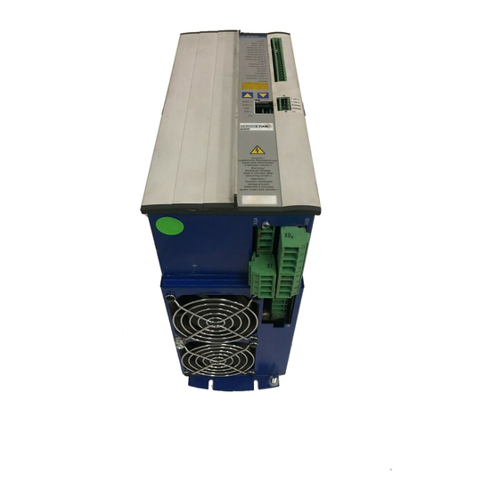
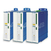
Kollmorgen SERVOSTAR 601 Servo Amplifier Manuals
Manuals and User Guides for Kollmorgen SERVOSTAR 601 Servo Amplifier. We have
2
Kollmorgen SERVOSTAR 601 Servo Amplifier manuals available for free PDF download: Instruction Manual, Assembly And Installation Manual
Kollmorgen SERVOSTAR 601 Instruction Manual (122 pages)
Digital Servo Amplifier
Brand:
Kollmorgen
| Category:
Amplifier
| Size: 5 MB
Table of Contents
Table of Contents
4
General
8
About this Manual
8
Target Group
8
Hints for the Online Edition (PDF Format)
8
Symbols Used
9
Standards Used
9
Abbreviations Used
10
Safety Instructions
12
Use as Directed
13
Prohibited Use
13
Approvals
14
Conformance with UL and Cul
14
EC Conformance
14
EC Declaration of Conformity
15
European Directives and Standards for the Machine Builder
16
GOST-R Conformance
17
Handling
18
Transport
18
Packaging
18
Storage
18
Maintenance
18
Disassembling
19
Repair
19
Disposal
19
Package Supplied
20
Nameplate
20
Part Number Scheme
21
Technical Description
22
The SERVOSTAR 600 Family of Digital Servo Amplifiers
22
Technical Data
24
Recommended Torque
25
Fusing
25
Ambient Conditions, Ventilation, Mounting Position
25
Conductor Cross-Sections
26
LED Display
26
Control for Motor Holding Brake
27
Grounding System
28
Electrical Brake Circuit
28
Switch-On and Switch-Off Behavior
30
Behavior in Standard Operation
31
Behavior in the Event of an Error (with Standard Setting)
32
Stop/Emergency Stop Function to en 60204
33
Stop: Standards
33
Emergency Stop: Standards
34
Shock-Hazard Protection
35
Leakage Current
35
Residual-Current Circuit Breakers (FI)
35
Isolating Transformers
35
Mechanical Installation
36
Safety Instructions
36
Guide to Mechanical Installation
36
Assembly
37
Dimensions
38
Electrical Installation
40
Safety Instructions
40
Guide to Electrical Installation
41
Wiring
42
Safety Instructions
42
Technical Data for Connecting Cables
43
Shielding Connection to the Front Panel
43
Motor Connector with Shieldplate
44
Components of a Servo System
45
Block Diagram
46
Pin Assignments
47
Connection Diagram (Overview)
48
Power Supply
49
Connection to Various Mains Supply Networks
49
Mains Supply Connection (X0)
50
Auxiliary Supply (X4)
50
DC Bus Link (X7)
50
Motor Connection with Holding Brake (X9)
51
External Brake Resistor (X8)
51
Feedback
52
Resolver (X2)
53
Sine Encoder 5V with Biss (X1)
54
Sine Encoder with Endat 2.1 or HIPERFACE (X1)
55
Sine Encoder Without Data Channel (X1)
56
Incremental Encoder / Sine Encoder with Hall (X1)
57
Incremental Encoder (X5)
58
Electronic Gearing, Master-Slave Operation
59
Connection to a SERVOSTAR Master, 5 V Signal Level (X5)
60
Connection to Encoders with 24 V Signal Level (X3)
60
Connection to a Sine-Cosine Encoder (X1)
61
Connection to an SSI Encoder (X5)
62
Connection to Stepper Motor Controllers (Step and Direction)
62
Step/Direction with 5 V Signal Level (X5)
63
Step/Direction with 24 V Signal Level (X3)
63
Encoder Emulations
64
Incremental Encoder Output - a Quad B (X5)
64
SSI Output (X5)
65
Digital and Analog Inputs and Outputs
66
Analog Inputs (X3)
66
Analog Outputs (X3)
67
Digital Inputs (X3)
68
Digital Outputs (X3)
69
RS232 Interface, PC Connection (X6)
70
Canopen Interface (X6)
71
Setup
72
Safety Instructions
72
Setup Software
73
General
73
Use as Directed
73
Software Description
73
Hardware Requirements
74
Operating Systems
74
Installation under WINDOWS
74
Quickstart Guide
75
Preparation
75
Unpacking, Mounting and Wiring the Servo Amplifier
75
Documents
75
Minimum Wiring for Drive Test
76
Connect
77
Important Screen Elements
78
Basic Setup
79
Motor (Synchronous)
80
Feedback
81
Save Parameters and Restart
82
Jogging the Motor (Speed Control)
83
Status
84
Monitor
84
Additional Setup Parameters
84
Multi-Axis Systems
85
Node Address for CAN-Bus
85
Baud Rate for CAN-Bus
85
Example of Connections for Multi-Axis System
86
Key Operation / LED Display
87
Key Operation
87
Status Display
87
Standard Menu Structure
88
Extended Menu Structure
88
Error Messages
89
Warning Messages
90
Removing Faults/Warnings
91
Expansions / Accessories
92
Option -AS-, Restart Lock for Personal Safety
92
Safety Instructions
92
Use as Directed
93
Block Diagram
93
Functional Description
94
Signal Diagram (Sequence)
94
Functional Test
95
Connection Diagram (Principle)
95
Application Example Category 1 According to EN954-1
96
Control Circuit
96
Mains Supply Circuit
96
Application Example Category 3 According to EN954-1
97
Control Circuit
97
Mains Supply Circuit
97
Flow Chart
98
Expansion Cards
99
Guide to Installation of Expansion Cards
99
Expansion Card -I/O-14/08
100
Front View
100
Technical Data
100
Light Emitting Diodes (Leds)
100
Select Motion Task Number (Sample)
100
Connector Assignments
101
Connection Diagram
102
Expansion Cards -PROFIBUS
103
Front View
103
Connection Technology
103
Connection Diagram
103
Expansion Card -SERCOS
104
Front View
104
Light Emitting Diodes (Leds)
104
Connection Technology
104
Connection Diagram
105
Modifying the Station Address
105
Modifying the Baud Rate and Optical Power
105
Expansion Card -DEVICENET
106
Front View
106
Connection Technology
106
Connection Diagram
106
Combined Module/Network Status-LED
107
Setting the Station Address (Device Address)
107
Setting the Transmission Speed
107
Bus Cable
108
Expansion Card -Ethercat
109
Front View
109
Leds
109
Connection Diagram
109
Expansion Card -SYNQNET
110
Front View
110
NODE ID Switch
110
Node LED Table
110
Synqnet Connection, Connector X21B/C (RJ-45)
110
Digital Inputs/Outputs, Connector X21A (Subd 15-Pin, Socket)
111
Connection Diagram Digital Inputs/Outputs, Connector X21A
111
Expansion Module -2CAN
112
Installation
112
Front View
112
Connection Technology
112
Connector Assignments
113
Connection Diagram
113
Special Accessories
114
Power Supply SINCOS
114
Terminating Adapter for Encoder Cables
114
Hall Dongle
115
Appendix 11.1 Glossary
116
Order Numbers
118
Servo Amplifiers
118
Expansion Cards
118
Connectors
118
Special Accessories
118
Repair-/Disposal Request Telefax Form
119
Index
120
Advertisement
Kollmorgen SERVOSTAR 601 Assembly And Installation Manual (98 pages)
Digital servo amplifier
Brand:
Kollmorgen
| Category:
Amplifier
| Size: 3 MB
Table of Contents
Edition
2
Table of Contents
3
Contents
3
Safety Instructions
6
European Directives and Standards
7
UL- Conformance
8
Abbreviations and Symbols
9
Symbols Used in this Manual
9
1 General
11
About this Manual
11
Prescribed Use (Use as Directed) of the Servo Amplifier
12
Nameplate
13
Instrument Description
13
Package Supplied
13
The Digital Servo Amplifiers of the Series SERVOSTAR 600
14
Operation Directly from Supply
14
Digital Servo Amplifier Concept
15
Connection to Different Mains Supply Networks
16
Components of a Servo System
17
Technical Data
18
External Fusing
18
Allowable Ambient Conditions, Ventilation, Mounting Position
19
Conductor Cross-Sections
19
Recommended Torque
19
LED Display
19
Grounding System
20
Control for Motor-Holding Brake
20
Regen Circuit
21
Switch-On and Switch-Off Behavior
22
Stop Function to en 60204 (VDE 0113)
22
Emergency Stop Strategies
23
2 Installation
25
Important Instructions
25
Assembly
26
Dimensions
27
Wiring
28
Connection Diagram
30
Example of Connections for Multi-Axis System
31
Pin Assignments
32
Notes on Connection Techniques
33
Shielding Connection to the Front Panel
33
Technical Data for Connecting Cables
34
Setup Software
35
General
35
Software Description
35
Use as Directed
35
Hardware Requirements
36
Operating Systems
36
Installation under WINDOWS 95 / 98 / 2000 / ME / NT / XP
36
3 Interfaces
37
Power Supply
38
Mains Supply Connection (X0)
38
Auxiliary Supply (X4)
38
DC-Link (X7)
38
Motor Connection with Brake (X9)
39
External Regen Resistor (X8)
39
Feedback
40
Resolver Connection (X2)
40
Encoder (X1)
41
Control Signals, Monitor Signals
42
Analog Inputs (X3)
42
Analog Outputs (X3)
43
Digital Control Inputs (X3)
44
Digital Control Outputs (X3)
45
Encoder Simulations
46
Incremental Encoder Simulation - a Quad B Position Output (X5)
46
SSI Encoder Simulation - Position Output (X5)
47
Interface for Master-Slave Operation, Encoder Input
48
Connection to a SERVOSTAR Master, 5V Signal Level (X5)
48
Connection to a Sine-Cosine Encoder (X1)
49
Connection to Encoders with 24V Signal Level (X3)
49
Interface for Stepper-Motor Controls (Pulse-Direction)
50
Connection to Stepper-Motor Controller with 5V Signal Level (X5)
51
Connection to Stepper-Motor Controller with 24V Signal Level (X3)
51
RS232 Interface, PC Connection (X6)
52
Canopen Interface (X6)
53
4 Setup
55
Important Notes
55
Parameter Setting
57
Multi-Axis Systems
57
Baud Rate for CAN-Bus
57
Node Address for CAN-Bus
57
Key Operation / LED Display
58
Key Operation
58
Status Display
58
Extended Menu Structure
59
Standard Menu Structure
59
Error Messages
60
Warning Messages
61
5 Extensions / Accessories
63
Option -AS-, Restart Lock for Personal Safety
63
Advantages of the -AS- Option
63
Functional Description
63
Block Diagram
64
Signal Diagram (Sequence)
64
Installation / Setup
65
Connection Diagram
65
Functional Test
65
Safety Instructions
65
Application Examples
66
Control Circuit
66
Moving Single Axes or Axis-Groups in Setting-Up Operation
66
Switching off Grouped Axes with Separate Working Areas
66
Mains Supply Circuit
67
Expansion Card -I/O-14/08
68
Fitting the Expansion Card
68
Technical Data
68
Light Emitting Diodes (Leds)
68
Position of the Connectors
69
Connector Assignments
70
Select Motion Task Number (Sample)
70
Connection Diagram
71
Expansion Card -PROFIBUS
72
Position of the Connectors
72
Fitting the Expansion Card
72
Connection Technology
73
Connection Diagram
73
Expansion Card -SERCOS
74
Position of the Connectors
74
Fitting the Expansion Card
74
Light Emitting Diodes (Leds)
75
Connection Technology
75
Connection Diagram
75
Expansion Card -Devicenet
76
Position of the Connectors
76
Fitting the Expansion Card
76
Connection Technology
77
Connection Diagram
77
Combined Module/Network Status LED
77
Expansion Card- ETHERNET
78
Fitting the Expansion Card
78
Connectors
78
Leds
78
Position of the Connectors
79
Connection Diagram
79
Expansion Card for Single Axis Controller -SAC
80
Fitting the Expansion Card
80
Technical Data
80
Position of the Connectors
81
Connector Assignments
81
RS-232 Communication X17 (Subd 9-Pin, Plug)
81
Devicenet Communication X16 (Phönix, 5-Pin)
82
RS-485 Communication X17 (Subd 9-Pin, Plug)
82
Digital Inputs/Outputs, Connector X18 (Subd 26-Pin, Socket)
83
Expansion Module -2CAN
84
Position of the Connectors
84
Fitting the Expansion Module
84
Connection Technology
85
Connector Assignments
85
Connection Diagram
85
Accessories
86
External 24V DC / 5A Supply
86
External 24V DC / 20A Supply
87
External Regen Resistor Barxxx
88
External Regen Resistor BAR(U)XXX
89
Motor Choke Box 3YL-20
90
6 Appendix
91
Transport, Storage, Maintenance, Disposal
91
Removing Faults/Warnings
92
Glossary
94
Order Numbers
96
Index
97
North America
98
Advertisement
Related Products
Kollmorgen SERVOSTAR 601...620
Kollmorgen SERVOSTAR 603
Kollmorgen SERVOSTAR 606
Kollmorgen SERVOSTAR 600 Series
Kollmorgen SERVOSTAR 670
Kollmorgen SERVOSTAR 620
Kollmorgen SERVOSTAR 640...670
Kollmorgen SERVOSTAR 610
Kollmorgen SERVOSTAR 610-30
Kollmorgen SERVOSTAR 614
Kollmorgen Categories
Servo Drives
Amplifier
Touch terminals
DC Drives
Engine
More Kollmorgen Manuals
Login
Sign In
OR
Sign in with Facebook
Sign in with Google
Upload manual
Upload from disk
Upload from URL