GE Masoneilan 469 Series Manuals
Manuals and User Guides for GE Masoneilan 469 Series. We have 6 GE Masoneilan 469 Series manuals available for free PDF download: Instruction Manual, Manual, Communications Manual

GE Masoneilan 469 Series Manual (307 pages)
Motor Management Relay
Table of Contents
-
Overview9
-
Setpoint13
-
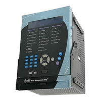
Installation19
-
Mechanical19
-
Description19
-
Installation20
-
Electrical26
-
Description33
-
Operation41
-
Overview41
-
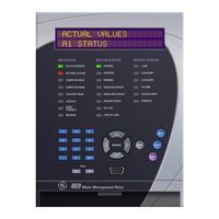
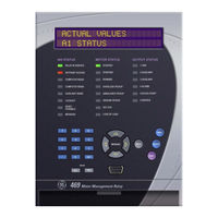
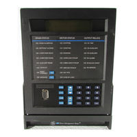
Faceplate41
-
Display42
-
Keypad44
-
Procedure45
-
Trips47
-
Alarms47
-
S1 469 Setup50
-
Passcode50
-
Function50
-
Preferences51
-
Serial Ports52
-
Clear Data55
-
Installation56
-
Function57
-
Examples58
-
Power System59
-
Description62
-
Test Switch62
-
Remote Reset62
-
Function67
-
Example67
-
Function68
-
Example68
-
Description70
-
Example70
-
Function77
-
Rtd Bias90
-
Undercurrent94
-
Function94
-
Example94
-
Function95
-
Example95
-
Ground Fault96
-
Start Inhibit100
-
Function100
-
Example100
-
Jogging Block101
-
Function101
-
Starts / Hour101
-
Restart Block102
-
Rtd Types103
-
Rtds 1 to 6104
-
Rtds 7 to 10105
-
Rtd 11106
-
Rtd 12107
-
Open Rtd Sensor108
-
Undervoltage109
-
Overvoltage110
-
Phase Reversal110
-
Frequency111
-
Power Factor113
-
Reactive Power114
-
Underpower115
-
Function115
-
Example115
-
Reverse Power116
-
Torque Setup117
-
Overtorque Setup117
-
S11 Monitoring118
-
Trip Counter118
-
Starter Failure118
-
Pulse Output122
-
S12 Analog I/O123
-
Function126
-
S13 469 Testing129
-
Simulation Mode129
-
Pre-Fault Setup130
-
Fault Setup131
-
Description134
-
Speed2 O/L Setup134
-
Actual Values139
-
Overview139
-
A1 Status140
-
Motor Status140
-
Last Trip Data141
-
Alarm Status143
-
Start Blocks145
-
Digital Inputs146
-
Real Time Clock146
-
A2 Metering Data147
-
Current Metering147
-
Temperature148
-
Voltage Metering149
-
Speed149
-
Power Metering150
-
Demand Metering151
-
Analog Inputs152
-
Phasors153
-
A3 Learned Data155
-
Motor Starting155
-
Rtd Maximums156
-
A4 Maintenance158
-
Trip Counters158
-
General Counters160
-
Timers160
-
A6 Product Info164
-
Model Info164
-
Calibration Info164
-
Diagnostics165
-
Example165
-
Flash Messages166
-
Communications169
-
Algorithm171
-
Timing171
-
Overview172
Advertisement
GE Masoneilan 469 Series Instruction Manual (336 pages)
Motor Management
Relay
Table of Contents
-
Installation
46-
Testing46
-
Description47
-
Order Codes51
-
Accessories51
-
-
-
Inputs52
-
Outputs53
-
Protection54
-
Monitoring57
-
Power Supply59
-
Cpu59
-
Testing59
-
Physical61
-
Description63
-
-
-
Description74
-
Description91
-
Display91
-
-
Rs232 Port93
-
Keypad94
-
-
File Support113
-
-
Description125
-
-
-
Triggered Events128
-
Phasors130
-
Event Recorder135
-
Modbus User Map136
-
Modbu User Map136
-
-
S1 469 Setup
150-
Passcode150
-
Preferences151
-
Communications152
-
Real Time Clock155
-
Default Messages155
-
Clear Data157
-
Installation158
-
-
S2 System Setup
159-
Current Sensing159
-
Voltage Sensing161
-
Power System161
-
Reduced Voltage163
-
-
-
Description166
-
Starter Status167
-
-
S4 Output Relays
176-
Description176
-
Relay Reset Mode176
-
-
S5 Thermal Model
178-
Thermal Model180
-
-
Overload Alarm202
-
Mechanical Jam202
-
Undercurrent203
-
Ground Fault205
-
-
Start Inhibit208
-
Jogging Block209
-
Restart Block211
-
-
Rtd Types212
-
Rtd S 1 to 6213
-
Rtd S 7 to 10214
-
Rtd 11216
-
Rtd 12217
-
Open Rtd Sensor217
-
-
-
Undervoltage218
-
Overvoltage220
-
Phase Reversal220
-
Frequency221
-
-
-
Power Factor223
-
Reactive Power224
-
Underpower225
-
Reverse Power226
-
Torque Setup226
-
Overtorque227
-
S11 Monitoring
228-
Trip Counter228
-
Starter Failure228
-
Demand229
-
Demand230
-
Pulse Output231
-
-
S13 469 Testing
240-
Simulation Mode240
-
Pre-Fault Setup241
-
Fault Setup242
-
-
-
Description245
-
Description253
-
-
A1 Status
254-
Network Status254
-
Motor Status255
-
Last Trip Data255
-
Alarm Status257
-
Start Blocks259
-
Digital Inputs259
-
Real Time Clock260
-
GE Masoneilan 469 Series Instruction Manual (260 pages)
Motor Management Relay
Table of Contents
-
Installation
36-
Testing36
-
-
Introduction
37 -
Overview
37-
Description37
-
Order Codes40
-
Accessories40
-
Inputs40
-
Outputs42
-
Protection42
-
Monitoring44
-
Power Supply44
-
Cpu45
-
Testing45
-
Physical46
-
-
Installation
47 -
Interfaces
71 -
-
Display71
-
RS232 Port73
-
Keypad73
-
-
Setpoints
107 -
Overview
107 -
S1 469 Setup
113-
Passcode113
-
Preferences113
-
Communications115
-
Real Time Clock117
-
Default Messages117
-
Clear Data119
-
Installation119
-
-
-
Voltage Sensing121
-
Power System122
-
Reduced Voltage123
-
-
-
Description125
-
Starter Status127
-
-
S4 Output Relays
134-
Description134
-
Relay Reset Mode134
-
-
S5 Thermal Model
135-
Thermal Model137
-
-
Overload Alarm156
-
Mechanical Jam156
-
Undercurrent157
-
Ground Fault159
-
-
Start Inhibit161
-
Jogging Block162
-
Restart Block163
-
-
-
Rtds 1 to 6165
-
Rtds 7 to 10166
-
Rtd 11167
-
Rtd 12168
-
Open RTD Sensor169
-
-
-
Undervoltage170
-
Overvoltage172
-
Phase Reversal172
-
Frequency173
-
-
-
Power Factor175
-
Reactive Power176
-
Underpower177
-
Reverse Power178
-
Torque Setup178
-
Overtorque179
-
S11 Monitoring
179-
Trip Counter179
-
Starter Failure180
-
Demand181
-
Pulse Output182
-
-
-
Pre-Fault Setup190
-
Fault Setup191
-
-
-
Description194
-
-
Actual Values
199-
Description201
-
-
Motor Status202
-
Last Trip Data202
-
Alarm Status204
-
Start Blocks206
-
Digital Inputs206
-
Real Time Clock207
-
-
A2 Metering Data
207-
Current Metering207
-
Temperature208
-
Speed209
-
Power Metering209
-
Demand Metering210
-
Analog Inputs210
-
Phasors211
-
Advertisement
GE Masoneilan 469 Series Instruction Manual (244 pages)
MOTOR MANAGEMENT RELAY
Brand: GE
|
Category: Control Unit
|
Size: 5 MB
Table of Contents
-
-
Mechanical15
-
Electrical22
-
-
-
4 Setpoints
51-
Overview51
-
S1 469 Setup56
-
Passcode56
-
Preferences57
-
Serial Ports58
-
Clear Data60
-
Installation61
-
-
-
Undercurrent94
-
Ground Fault96
-
-
Restart Block100
-
-
RTD Types101
-
Rtds 1 to 6102
-
Rtds 7 to 10103
-
Rtd 11104
-
Rtd 12105
-
Open RTD Sensor106
-
-
-
Undervoltage107
-
Overvoltage108
-
Phase Reversal108
-
Frequency109
-
-
-
Power Factor111
-
Reactive Power112
-
Underpower113
-
Reverse Power114
-
Torque Setup115
-
Overtorque Setup115
-
S11 Monitoring116
-
Trip Counter116
-
Starter Failure117
-
Pulse Output119
-
-
S12 Analog I/O121
-
S13 469 Testing127
-
Simulation Mode127
-
Pre-Fault Setup128
-
Fault Setup129
-
GEPM Use Only131
-
-
-
Description132
-
-
-
5 Actual Values
135-
Overview135
-
Last Trip Data135
-
Alarm Status135
-
Motor Status137
-
Alarm Status139
-
Start Blocks141
-
Digital Inputs142
-
Real Time Clock142
-
-
A2 Metering Data143
-
Current Metering143
-
Temperature144
-
Voltage Metering145
-
Speed145
-
Power Metering146
-
Demand Metering147
-
Analog Inputs147
-
Phasors148
-
-
A3 Learned Data150
-
Motor Starting150
-
RTD Maximums151
-
-
A4 Maintenance153
-
Trip Counters153
-
General Counters154
-
Timers155
-
-
A6 Product Info158
-
Diagnostics159
-
Flash Messages160
-
GE Masoneilan 469 Series Communications Manual (150 pages)
Motor Management Relay
Table of Contents
-
-
Timing8
-
-
-
Memory Map23
-
Data Formats113
-
Format Codes113
-
-
Overview128
-
Specific Objects135
-
Index147
-

GE Masoneilan 469 Series Instruction Manual (28 pages)
Position Transmitter and Limit Switch
Brand: GE
|
Category: Transmitter
|
Size: 1 MB
Table of Contents
-
Calibration15
-
Maintenance21
-
Annex I24
-
Annex II26
-
Annex III27
Advertisement