Table of Contents
Advertisement
Quick Links
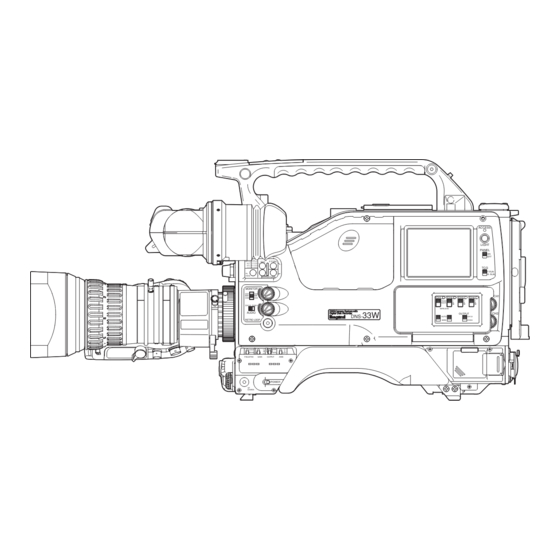
OPERATION MANUAL
DNS - 33W
ECC
ND
4 1.6%
D 8 00 0K
ECC
P.FUNC
+
36.2%
C 6 30 0K
22.5%
B 4 30 0K
11.0%
A 3 20 0K
FIL
-
HEAD
HYPER GAIN
MONITOR
CH1
CH3
MIX
MIX
CH2
CH4
CH1/2
CH3/4
DNG
DNG Camera ra Sy
System wit
with
AUDIO
Di Digital
ital D Disk Record
order
33W
DNS-
RETRO LOOP
STBY
・L
CAM
・A
・M
・B
SAVE
BARS
・H
OFF
FIELDPAK
GAIN
OUTPUT
AWB
POWER
VF
CHARA
ACCESS
LIGHT
PANEL
ON
OFF
TCG
F-RUN
R- RUN
CH1
CH1
CH2
CH3
CH4
F
F
FRONT
F
REAR
R
R
R
W
W
W
WIRELESS
OUTPUT
CH2
AUTO
CH1/2
MAN
CH3/4
3
Advertisement
Table of Contents

Related Manuals for Ikegami Editcam 3 DNS-33W


Summary of Contents for Ikegami Editcam 3 DNS-33W
- Page 1 ACCESS LIGHT PANEL 4 1.6% D 8 00 0K P.FUNC 36.2% C 6 30 0K 22.5% B 4 30 0K 11.0% A 3 20 0K F-RUN R- RUN HEAD HYPER GAIN MONITOR FRONT REAR CH1/2 CH3/4 WIRELESS DNG Camera ra Sy System wit with AUDIO...
- Page 3 ACCESS LIGHT PANEL P.FUNC 4 1.6% D 8 00 0K 36.2% C 6 30 0K 22.5% B 4 30 0K 11.0% A 3 20 0K F-RUN R- RUN HEAD HYPER GAIN MONITOR FRONT REAR CH1/2 CH3/4 WIRELESS DNG C Camera ra Sy System wit with AUDIO...
- Page 4 Copyright © 2005 Ikegami Tsushinki Co., Ltd. We reserve the copyright on the software we create. No part of this publication may be modified or reproduced in any form, or by any means, without prior written permission from Ikegami Tsushinki Co., Ltd.
-
Page 5: Safety Precautions
SAFETY PRECAUTIONS SAFETY PRECAUTIONS The safety precautions on the use of DNS-33W are described below. Please read these precautions thoroughly before use. 1. Notes on this Manual (1) This manual is written for readers with a basic knowledge on cameras, therefore the definitions of the technical terms are omitted. - Page 6 (once every 3 years or 8000 hours use) is recommended to extend the life and safe use of this product for a long time. Please contact Ikegami sales and service centers or Techno Ikegami Co., Ltd. for the regular maintenance and repair of our products.
-
Page 7: How To Use Operation Manual
HOW TO USE OPERATION MANUAL HOW TO USE OPERATION MANUAL The Editcam3, DNS-33W Camera Operation Manual is intended to describe how to operate DNS-33W Camera. This Operation Manual is written for people who have some basic knowledge and understanding of a television camera, so explanation of technical terms is omitted here. - Page 8 DNS-33W DNS-33W 0503 VOL1 (E)
-
Page 9: Table Of Contents
4.9 Operations of Recorder Section ....... 4-8 4.10 Operations of Menus of Recorder Section ..... 4-11 4.11 Shooting in Particular Environment ....... 4-13 © Copyright March 2005 (Ikegami) 1st Edition : March 2005 (Ikegami) DNS-33W 0503 VOL1 (E) DNS-33W 0503 VOL1 (E) - Page 10 DNS-33W DNS-33W 0503 VOL1 (E)
- Page 11 QUICK START GUIDE "QUICK START GUIDE" explains a series of basic operations necessary for shooting and is written for people who have some basic knowledge of a television camera and who have experience using the camera. This guide explains main operations after camera equipment is connected to the camera.
- Page 12 DNS-33W DNS-33W 0503 VOL1 (E)
-
Page 13: Preparations Before Shooting
After the camera is powered on normally, the LEDs once turn off. Then, the color LCD on the right side of the camera displays the logo "Ikegami" and the Status screen. When a FieldPak2 (hereinafter called FP2) has been loaded in the camera, the logo "Ikegami" is displayed and the disk is recognized automatically (recognition requires a few minutes). -
Page 14: Fieldpak2 (Fp2) Loading
QUICK START GUIDE FieldPak2 (FP2) Loading 1. Insert FP2 by pressing the EJECT key after the camera is powered on. 2. Close the eject cover. Push the cover firmly until it clicks into position. The FP2 will be recognized automatically just after the loading. -
Page 15: Disk Initialization
QUICK START GUIDE Press the "PRJ" button. 3. Press the "PRJ" (PROJECT) button on the screen. PROJECT SWITCHER : CAMERA VIDEO AUDIO TEST ON TIMECODE 4. Change the compression format (DV or JFIF) by pressing the This button changes compression ratio. This button changes compression button on the right. - Page 16 QUICK START GUIDE 1. Touch the Status screen to display the "BASE" menu. Press the "DSK" button. 2. Press the "DSK" (DISK OPERATIONS) button on the screen. AUDIO / VIDEO DISK OPERATIONS RECORD / PLAYBACK SYSTEM SETUP Press the "FMT" button. 3.
-
Page 17: Shooting
QUICK START GUIDE Shooting Pressing the REC button starts recording. Pressing the REC button once again stops recording. REC Button There are 2 REC buttons on the camera body, and there is a VTR button on the lens. The VTR button on the lens works the same as the REC button. -
Page 18: Playing
QUICK START GUIDE Playing There are two ways to play recorded image, normal playback and REC-REVIEW playback. Normal Playback Pressing the PLAY key starts playback of the recorded image. To select a desired clip, use the PRIOR key or the NEXT key on the top of the camera or |<< key or >>| key on the right side of the camera. -
Page 19: Rec-Review Playback
QUICK START GUIDE REC-REVIEW Playback When the RET button on the handle or on the lens is pressed with the output set to "CAM", the ending part for the last several seconds of the last clip is played. Notice •... -
Page 20: Special Recording Modes
QUICK START GUIDE Special Recording Modes Retro Loop Recording Pressing RETRO LOOP switch on the right side of the camera starts the RETRO LOOP mode. By starting the RETRO LOOP mode in advance, the images shot before pressing the REC button are additionally recorded. -
Page 21: Time Lapse Recording
QUICK START GUIDE 4. By pressing the "RETROLOOP LENGTH" button, characters By pressing the "RETROLOOP LENGTH" button, characters are highlighted. Set the are highlighted. Set the retro loop time length by pressing retro loop time length by operating the control switch panel. - Page 22 QUICK START GUIDE Press the "REC" button. 3. Press the "REC" (RECORD) button on the screen. RECORD PLAYBACK NAVIGATION Set recording time by the "TIMELAPSE RECORD" button. 4. Press the "TIMELAPSE OUT OF" button, and input "00:00:06:00" using |<< key and >>| key. RETROLOOP LENGTH : After the completion of the input, press the "TIMELAPSE 0 : 15 mss...
-
Page 23: Table Of Control Key Operations
QUICK START GUIDE Table of Control Key Operations To operate the recorder section, perform following key operations. Control Switch Panel on the Right Side of the Camera Control Keys on the Top of the Camera SHIFT |<< >>| FRONT <... -
Page 24: Menu Structure Of The Recorder Section
QUICK START GUIDE Menu Structure of the Recorder Section Menu structure of the recorder section is described below. Refer to this for menu operations. For details of each setting item of the menu, refer to "6. SETTINGS AND ADJUSTMENT OF RECORDER SECTION". -
Page 25: Status Screen Display
QUICK START GUIDE Status Screen Display The Status screen displays setting information and camera status. This is the initial screen displayed just after the camera is powered on. Status of the camera can be checked before shooting. Status screen display is explained below. - Page 26 QUICK START GUIDE 5. Remaining recording time Displays remaining recording time calculated by remaining FP2 disk amount. 6. Disk format type Displays format type of loaded FP2. Display Format Type FAT32 Single partition by FAT32 No display An FP2 is not inserted, or an unformatted FP2 is loaded.
- Page 27 QUICK START GUIDE DV25 PAL 48k [When Recording is Stopped] DVCPRO Displays only time code. LOCAL POWER 15.0V 02:43:49 FAT32 VID = CAMERA READY 0001/0002 0003 00 : 02 : 06 : 14 BIN FAG7CM 1M NLT 1 .0 .9 Only time code is displayed.
- Page 28 DNS-33W DNS-33W 0503 VOL1 (E)
-
Page 29: Outline
Installs a 0.18µm-rule digital process IC which is also adjusted by moving it forward and back, and left and right installed to Ikegami's top-class broadcast HDTV cameras. when VF is mounted. In addition, RET switch and REC Processes after PRE KNEE are all digitally processed;... - Page 30 1 - 2 1. OUTLINE 1.1.4 Accessory and System Operation Unislot A built-in wireless receiver can be installed to the Unislot mounted on the rear of the camera without cable. System operation MA operation with MA adapter "MCA-400" supporting 26- pin external VTR connector and camera control unit "MA- 400"...
-
Page 31: Name And Function
2. NAME AND FUNCTION 2 - 1 NAME AND FUNCTION This chapter explains the names and functions of camera parts. 2.1 Camera Front Side This section explains the names and functions of the parts on the front of the camera. PEAKING CONTRAST BRIGHT... - Page 32 2 - 2 2. NAME AND FUNCTION 7 AWB/ABB Switch 9 REC Button Used to adjust white balance, black balance, and black Used to start or stop recording to an FP2. This switch shading automatically. works in parallel with the REC button on the lens and the handle.
-
Page 33: Camera Rear Side
2. NAME AND FUNCTION 2 - 3 2.2 Camera Rear Side This section explains the names and functions of the parts on the rear of the camera. LINE +48V LINE +48V -20dB OFF BACK TALLY Lamp MON OUT Connector BACK TALLY Switch DC IN Connector AUDIO SELECT Switches PHONE Terminal... - Page 34 2 - 4 2. NAME AND FUNCTION 11 CAMERA REMOTE Connector 9 PHONE Terminal Connector used to connect the optional remote control Used to connect the earphone for audio monitor. When box (RM-11, RCP-50, RCP-11, RS-11, etc.) for camera this terminal is used, the sound from the speaker stopped section.
-
Page 35: Camera Right Side (1)
2. NAME AND FUNCTION 2 - 5 2.3 Camera Right Side (1) This section explains the names and functions of the parts on the right side of the camera. Read this section with "2.4 Camera Right Side (2)". 9 10 2 3 4 P.FUNC 4 1.6%... -
Page 36: Audio Level Knob
2 - 6 2. NAME AND FUNCTION 3 AUDIO LEVEL Knob Setting Value Description Adjusts the input sound level of the CH1/CH2 microphone The recording time goes on regardless of F-RUN during recording to an FP2. operations of the recorder section. This mode is Adjust the input sound level within the range set in the selected when the recording time of the camera should be synchronized with another external... -
Page 37: Fieldpak Switch
2. NAME AND FUNCTION 2 - 7 22 FIELDPAK Switch 27 MONITOR AUDIO CHANNEL SELECT Switch Used to turn ON/OFF the power of the hard disk motor in an FP2. Used to change the audio channel output from the speaker or earphone. Setting Value Description The MONITOR LEVEL knob adjusts the output level of... -
Page 38: Fil Head Button
2 - 8 2. NAME AND FUNCTION 32 FIL HEAD Button Used to change the control priority of the ECC filter between the camera head and the remote controller. Remote control of the ECC filter becomes available when a remote controller, which is capable of filter control, is connected to the camera head or various types of extension equipment. -
Page 39: Camera Right Side (2)
2. NAME AND FUNCTION 2 - 9 2.4 Camera Right Side (2) This section explains the names and functions of the parts on the right side of the camera. Read this section with "2.3 Camera Right Side (1)". LIGHT PANEL 4 1.6% D 8 00 0K P.FUNC... -
Page 40: Stop Key
2 - 10 2. NAME AND FUNCTION 6 STOP Key 10 AUDIO OUTPUT Switch Stops all modes playback/record. Also used in conjunction Used to select output (CH1/CH2 or CH3/CH4) from the with various keys. AUDIO OUT connector on the rear of the camera. Operated Key Description 11 REC Key... - Page 41 2. NAME AND FUNCTION 2 - 11 14 SHIFT Key Used in conjunction with various keys. (Record) • SHIFT key + REC key Starts recording by time-lapse. (Edit) SHIFT key + IN key Sets the IN point at the current frame. SHIFT key + OUT key Sets the OUT point at the current frame.
-
Page 42: Camera Left Side
2 - 12 2. NAME AND FUNCTION 2.5 Camera Left Side This section explains the names and functions of the parts on the left side of the camera. PUSH DNG Camera System with Digital Disk Recorder -20dB GL IN TC IN AB12 VIDEO AUDIO... - Page 43 2. NAME AND FUNCTION 2 - 13 8 MIC POWER Switch 15 GENLOCK IN Connector Used to select the type of power supplied to the Input the SYNC signal (black burst or composite signal) microphone connected to the MIC connector at the front from an external system to have the camera genlocked.
-
Page 44: Viewfinder (Vf15-32A-S)
2 - 14 2. NAME AND FUNCTION 2.6 Viewfinder (VF15-32A-S) This section explains the names and functions of the viewfinder (VF15-32A-S) parts. VF Cable ZEBRA Switch EYEPIECE Release Lever TALLY Switch Diopter Adjustment Lever FRONT TALLY Lamp PEAKING Knob REAR TALLY Lamp CONTRAST Knob (with Switch) BRIGHTNESS Knob... - Page 45 2. NAME AND FUNCTION 2 - 15 2.6.1 Displays in the Viewfinder Center Marker, Safety Markers and Frame Marker In addition to the LED indicators on the VF, marker and character displays are also provided on the VF screen. • The Center Marker is used to ascertain the center of Details are provided below.
-
Page 46: Side Mask Function
2 - 16 2. NAME AND FUNCTION Audio Level Indicator Switching the Display The recording level is displayed in the form of a bar The character displays can be set by "DISPLAY MODE" graph on the Audio Level Indicator. of the camera menu. The characters to be displayed on the VF screen differ depending on the mode. -
Page 47: Status Displays
2. NAME AND FUNCTION 2 - 17 Character Display Status displays Lens extender operation display Special recording operating mode display Displays operating mode during the special recording. During retro loop record: RETRO During time lapse record : T.LPS EX RETRO 00:00:00:00 0001 Position mark 00:00:00... - Page 48 DNS-33W DNS-33W 0503 VOL1 (E)
-
Page 49: Installation And Connection
3. INSTALLATION AND CONNECTION 3 - 1 INSTALLATION AND CONNECTION This chapter explains how to install and connect the camera equipment. 3.1 Preparation to Connect 3.1.1 Making Sure that Power Switch is Turned OFF Make sure that the power switch is turned OFF when the camera and peripheral equipment are connected. For the power switch and turning off procedure of peripheral equipment, refer to the manual of each peripheral equipment. - Page 50 3 - 2 3. INSTALLATION AND CONNECTION 3.1.2 Connection Diagram This section shows the connection diagram of the camera equipment. DNS-33W DNS-33W 0503 VOL1 (E)
- Page 51 3. INSTALLATION AND CONNECTION 3 - 3 3.1.3 Connection Example of Camera and Main Equipment This section shows a main connection example of the camera and peripheral equipment. DNS-33W 0503 VOL1 (E) DNS-33W...
-
Page 52: Mounting On A Tripod
3 - 4 3. INSTALLATION AND CONNECTION 5. After inserting the Front wedge of the camera, tighten the 3.2 Mounting on a Tripod Lock lever until the camera is completely fixed. At this time, rotate the lever until it clicks into position. This section explains how to mount the camera on a tripod. -
Page 53: Mounting The Lens
3. INSTALLATION AND CONNECTION 3 - 5 8. Position the camera to the desired pan and tilt angles and 5. Fix the Pigtail Cable to the Cable Clamp to remove any secure it. slack. Camera Right Side Camera Front Side PEAKING CONTRAST BRIGHT... -
Page 54: Mounting The Viewfinder
3 - 6 3. INSTALLATION AND CONNECTION CAUTION 3.4 Mounting the Viewfinder Be careful not to catch your fingers in the Lock lever This section explains how to mount the VF (VF15-32A-S) to or Guide-Rail when mounting the VF, or you can be the Camera. -
Page 55: Connecting A Microphone
3. INSTALLATION AND CONNECTION 3 - 7 Removing and Attaching the Eyepiece 3.5.1 Connecting a Front Microphone This section explains how to remove the eyepiece from the 1. Check that the microphone holder is attached to the VF. If it is not attached, attach a microphone holder to the microphone holder attaching mount. -
Page 56: Power Connection
3 - 8 3. INSTALLATION AND CONNECTION Disconnecting the Front Microphone 2. Set the AUDIO SELECT switches on the rear of the This section explains how to disconnect the front microphone camera depending on the microphones to be used. from the camera. Camera Rear Side 1. - Page 57 3. INSTALLATION AND CONNECTION 3 - 9 3.6.1 How to Supply Power from an AC Pack Disconnecting the AC Pack This section explains how to supply power from an AC pack. This section explains how to disconnect the AC pack. WARNING 1.
-
Page 58: Connecting A Monitor
3 - 10 3. INSTALLATION AND CONNECTION Disconnecting the Battery Pack 3.7.1 Connection through MONITOR OUT Connector This section explains how to disconnect the battery from the This section explains how to connect the camera and the PM camera. (picture monitor)/WFM (waveform monitor) through the MONITOR OUT connector. - Page 59 3. INSTALLATION AND CONNECTION 3 - 11 3.7.2 Connection through VIDEO OUT Connector This section explains how to connect the camera and the monitors (PM/WFM) through the VIDEO OUT connector. 1. Connect VIDEO OUT connector at the left side of the camera and the monitor with a coaxial cable.
- Page 60 DNS-33W DNS-33W 0503 VOL1 (E)
-
Page 61: Operation
4. OPERATION 4 - 1 OPERATION This chapter explains how to operate the camera. Operate the camera according to the following procedures: 4.1 Operation Procedures 1. Installation and Connection See Section 3 2. Switch Position Checks See Section 4.2 3. Turning ON Power See Section 4.3 4. -
Page 62: Switch Position Checks
4 - 2 4. OPERATION 4.2.2 Front Side of the Camera 4.2 Switch Position Checks When the camera is purchased and used for the first time, set the switches and knobs to the positions indicated in the figure below and ensure that the camera operates normally. After checking the camera operations, set the switches and knobs to match them to the environments and required conditions of shooting. -
Page 63: Turning On Power
Then, the color LCD on the right side of the camera Switch Name Switch Position displays the logo "Ikegami" and the Status screen. MIC ATT switch When an FP2 has been loaded in the camera, the logo AUDIO SELECT... -
Page 64: Adjusting The Viewfinder
4 - 4 4. OPERATION 4.4 Adjusting the Viewfinder 4.5 Adjusting the Lens If you want to see the images more clearly or to make the Refer to the manual of each lens for the standard operation edges of the image sharper, adjust the VF to match the of the lens. -
Page 65: Output Signal Checks
4. OPERATION 4 - 5 4.5.2 How to Use the B3 Mount Lens AUTO IRIS Operation If the iris operation is too slow or, on the contrary, too fast and causes hunting problems in the AUTO IRIS mode, set the auto iris sensitivity adjustment trimmer of the lens using the following procedures: 1. -
Page 66: Auto White Balance, Auto Black Balance And Auto Black Shading
4 - 6 4. OPERATION 4.7.1 Auto White Balance 1. Use the AWB SELECT switch to select the memory (Ach ・L ・A STBY ・M ・B BARS SAVE ・H or Bch) in which to store the execution result. FIELDPAK GAIN OUTPUT Switch Description Ach memory... -
Page 67: Fieldpak Loading And Changing
4. OPERATION 4 - 7 4.7.3 Auto Black Shading Notice Following the auto black balance adjustment, black shading When the "AWB WITH CC FILT" mode is set to adjustment can be automatically performed. "ON", the camera automatically measures the color temperature of the subject and selects the best color 1. -
Page 68: Operations Of Recorder Section
4 - 8 4. OPERATION 3. Push the FieldPak holder cover to close. Notice Be sure to use a formatted FP2. For how to format the FP2, refer to "6.3.1 FMT Menu". 3. Select the output signal of the camera for "SWITCHER" of "AUDIO/VIDEO"... - Page 69 4. OPERATION 4 - 9 7. Recording of a clip is started by pressing any one of the 8. To stop the recording, press the STOP key on the control REC button on the front of the camera, the REC button switch panel on the camera's right side, the REC button on the handle, the VTR button on the lens, and the REC on the camera's front side/carrying handle, or the VTR...
- Page 70 4 - 10 4. OPERATION Normal Playback Notice 1. Make sure a recorded FP2 is in the FieldPak holder. To play the same clip again from the beginning, If the holder is empty, place a recorded FP2 in the press the PLAY key after pressing the IN key. When holder.
-
Page 71: Operations Of Menus Of Recorder Section
4. OPERATION 4 - 11 3. Select the clip you want to delete using the PRIOR key 7. If you want to place the FP2 on standby after deletion, or the NEXT key on the top of the camera or on the set the FIELDPAK switch on the right side of the camera control switch panel. - Page 72 4 - 12 4. OPERATION 4.10.2 Display Changing AUDIO SCRUB : This section explains the changing method as the operation 0 frames common to all the screens. 1. Touch the LCD while the Status screen is displayed on it. REVIEW LENGTH : The display changes to the "BASE"...
-
Page 73: Shooting In Particular Environment
4. OPERATION 4 - 13 Character Input 4.11 Shooting in Particular Environment Character input is available when the FP2 volume name or the bin name is set. When the camera is used in a particular environment such as places where the temperature is extremely low, where the 1. - Page 74 DNS-33W DNS-33W 0503 VOL1 (E)
-
Page 75: Settings And Adjustment Of Camera
5. SETTINGS AND ADJUSTMENT OF CAMERA 5 - 1 SETTINGS AND ADJUSTMENT OF CAMERA This chapter explains how to set and adjust various camera settings. 5.1 Microphone Power/Level Down Setting Camera Left Side PUSH DNG Camera System with Digital Disk Recorder MIC POWER Switch MIC ATT Switch -20dB... -
Page 76: Selecting Shutter Speed
5 - 2 5. SETTINGS AND ADJUSTMENT OF CAMERA 5.2 Selecting Shutter Speed Activating Preset/Variable Shutter Speed Mode DNS-33W has two shutter speed settings: Preset Shutter with six different levels of shutter speed set in advance, and Variable Shutter for which the user can set the shutter speed to suit different shooting situations. -
Page 77: Enhancing The Vertical Resolution (Super-V Mode)
5. SETTINGS AND ADJUSTMENT OF CAMERA 5 - 3 5.3 Enhancing the Vertical Resolution 5.4 Improving the Low Luminance (Super-V mode) Reproduction (Black Stretch/Black Press) Super-V function enhances the vertical resolution. Black Stretch Notice The human eye has a much greater dynamic range than a TV camera. -
Page 78: Screen Detail Enhancement (Dtl)
5 - 4 5. SETTINGS AND ADJUSTMENT OF CAMERA Operating Black Stretch/Black Press Function 5.5.2 Soft DTL There are three ways to activate the Black Stretch/Black Press When shooting a subject that has a significant difference in functions: allocating function to the P.FUNC switch on the its black and white shading, a glare may occur in the lighter right side of the camera, activating from the Maintenance area. -
Page 79: Switching The Gain
5. SETTINGS AND ADJUSTMENT OF CAMERA 5 - 5 5.6 Switching the Gain Notice When shooting the camera under the conditions such as in When the HYPER GAIN function is activated, the evening, night time, or indoor use, the gain (sensitivity) of noise component increases as well as the gain the camera needs to be adjusted to suit subjects with different becomes high. -
Page 80: Using The Memory Card
5 - 6 5. SETTINGS AND ADJUSTMENT OF CAMERA 2. Press and hold the VF CHARA button for more than 2 5.7 Using the Memory Card seconds, and holding the VF CHARA button, press the SET button to display "MEMORY CARD" of the The camera settings can be saved to/loaded from a memory Maintenance Menu (2/3). - Page 81 5. SETTINGS AND ADJUSTMENT OF CAMERA 5 - 7 4. Select the data in the specified file on "LOAD DATA". CAUTION Data Type Description • When the camera settings saved on the memory card are loaded, all previous camera settings will LENS1-8 All lens files be overwritten.
- Page 82 5 - 8 5. SETTINGS AND ADJUSTMENT OF CAMERA 4. When all the characters in the parenthesis are set, the 5.7.5 Naming the Memory Card character input mode ends and the new file name is set. The memory card can be named. If the file name is less than 8 characters long, be sure to MEMORY CARD input blank spaces in the remaining fields.
- Page 83 5. SETTINGS AND ADJUSTMENT OF CAMERA 5 - 9 Memory Card • Always press the memory card eject button to remove the memory card from the slot. When the camera is powered on, removing the memory card without pressing the memory card eject button may damage the memory card data and the memory card itself.
-
Page 84: Allocating Functions To
5 - 10 5. SETTINGS AND ADJUSTMENT OF CAMERA 4. Test the memory card to confirm that it is formatted 3. While the selection display is flashing, scroll through the correctly by selecting "M. CARD TEST" from the functions that can be allocated to the P.FUNC switch by submenus. - Page 85 5. SETTINGS AND ADJUSTMENT OF CAMERA 5 - 11 4. Display the desired function and press the SET button while the selection is flashing. The selected function is 3. Press the P.FUNC switch again. AHD is executed, allocated to the P.FUNC switch (IRIS+CORR for the "A.SKIN HUE OK"...
-
Page 86: Settings In The Menu
5 - 12 5. SETTINGS AND ADJUSTMENT OF CAMERA 1. Press and hold the PRESET button with a pointed stick, 5.10 Settings in the Menu for example the tip of a ballpoint pen. The following message is displayed: There are two menu modes available for DNS-33W: "Normal Menu"... - Page 87 5. SETTINGS AND ADJUSTMENT OF CAMERA 5 - 13 Operation of the "Maintenance Menu" 4. As in the Normal Menu, rotate the rotary pulse switch, put the flashing cursor on the detailed setting item to set This section explains how to operate the Maintenance Menu. up, and then press the SET button to confirm the selected There are 3 screens for the Maintenance Menu: "***MENU item for submenus.
- Page 88 5 - 14 5. SETTINGS AND ADJUSTMENT OF CAMERA 5.10.2 Structure of Normal Menu This section shows the structure of the Normal Menu. The menu items displayed on the Normal Menu can be changed in MENU CUSTOMIZE in the Maintenance Menu (3/3). Here, the factory setting is described: Submenu Detailed Setting Items...
- Page 89 5. SETTINGS AND ADJUSTMENT OF CAMERA 5 - 15 Submenu Detailed Setting Items Mode Selection Default Value Function LOW/MID/HIGH LOW GAIN -3, 0, +3, +6, +9, 0 dB Allocates a gain value in the "L" position of the GAIN MODE +12 dB GAIN SELECT switch MID GAIN...
- Page 90 5 - 16 5. SETTINGS AND ADJUSTMENT OF CAMERA 5.10.3 VF DISPLAY (Selecting various status display modes on the VF) TITLE Area VF DISPLAY sets up items and contents displayed on the ACTION Area VF, for example turning ON/OFF the markers, etc. DISPLAY MODE DISPLAY MODE selects the display mode of various Area Name...
- Page 91 5. SETTINGS AND ADJUSTMENT OF CAMERA 5 - 17 VF DISPLAY2 (Submenus to select mode for DISPLAY SELECT (Character display setting) various displays on the VF) DISPLAY SELECT turns each character display ON/OFF. VF DISPLAY2 sets up the item contents to display on the 1.
- Page 92 5 - 18 5. SETTINGS AND ADJUSTMENT OF CAMERA OUTPUT SIGNAL MONITOR OUT2 (Submenus to select mode for various OUTPUT SIGNAL selects the video signal channel (ENC, Y, displays on the monitor line) R+G+B, R, G, or B) displayed on the MON connector. MONITOR OUT2 sets up the item contents to display on the 1.
- Page 93 5. SETTINGS AND ADJUSTMENT OF CAMERA 5 - 19 Setting the Zebra 1 Signal 5. On the CURRENT column asterisks are displayed next to the functions currently selected to display the warning. 1. Select "ZEBRA 1 IND", and rotate the rotary pulse switch to select "ON".
- Page 94 5 - 20 5. SETTINGS AND ADJUSTMENT OF CAMERA DISPLAY (Setting the title display) The values must be in LOW<MID<HIGH<HYPER 1. Select "DISPLAY". relationship. 2. Select "ON" or "OFF" and confirm. Reference For details on how to use the HYPER GAIN, refer to POSITION (Setting the title position) "5.6.2 Activating the HYPER GAIN".
- Page 95 5. SETTINGS AND ADJUSTMENT OF CAMERA 5 - 21 SCENE NUMBER (Loading the scene files) DTL GAIN (Adjusting DTL GAIN level) SCENE NUMBER loads the scene files set in advance. "DTL GAIN" adjusts the DTL GAIN level according to the shooting environment.
- Page 96 5 - 22 5. SETTINGS AND ADJUSTMENT OF CAMERA RET SOURCE Normally, use the camera with "YES" setting. In special (Selecting the return video signal source) cases when only the remote controllers with the AWB "RET SOURCE" selects the source of return video signals. memory switch function and the setting should remain as To display the external VTR (playback or Rec Review) or the "AWB OFF", select "NO".
- Page 97 5. SETTINGS AND ADJUSTMENT OF CAMERA 5 - 23 5.10.13 Structure of Maintenance Menu (1/3) This section shows the structure of the Maintenance Menu (1/3). Submenu Detailed Setting Items Mode Selection Default Value Function VF DISPLAY DISPLAY MODE OFF, 1, 2 Selects the display mode for various characters displayed on the VF SAFETY AREA...
- Page 98 5 - 24 5. SETTINGS AND ADJUSTMENT OF CAMERA Submenu Detailed Setting Items Mode Selection Default Value Function LOW/MID/HIGH LOW GAIN -3, 0, +3, +6, +9, 0 dB Allocates a gain value in the "L" position of the GAIN MODE +12dB GAIN switch MID GAIN...
- Page 99 5. SETTINGS AND ADJUSTMENT OF CAMERA 5 - 25 5.10.14 Structure of Maintenance Menu (2/3) This section shows the structure of the Maintenance Menu (2/3). Submenu Detailed Setting Items Mode Selection Default Value Function CPU SYSTEM CONTROL LEVEL CONTROL OPE, OFF Sets the various level data controlled by the CPU to "0"...
- Page 100 5 - 26 5. SETTINGS AND ADJUSTMENT OF CAMERA Submenu Detailed Setting Items Mode Selection Default Value Function VIDEO PROCESS MODE Submenu Detailed Setting Items Mode Selection Default Value Function GRP1 - GAMMA OFF, 0.35, 0.4, 0.45 0.45 Sets up the preset GAMMA value GAMMA・FLARE・...
- Page 101 5. SETTINGS AND ADJUSTMENT OF CAMERA 5 - 27 Submenu Detailed Setting Items Mode Selection Default Value Function MEMORY CARD LOAD FILE (8 characters) Selects the file name to load from the memory card LOAD DATA ALL DATA, Sets up the data to load from the memory card MENU DATA, VF DATA, SNAP SHOT,...
- Page 102 5 - 28 5. SETTINGS AND ADJUSTMENT OF CAMERA 5.10.16 AWB/ABB MODE (Selecting AWB 5.10.15 CPU SYSTEM CONTROL (Selecting function and setting the reference data) operation mode of the Camera) AWB/ABB MODE selects the operation mode for AWB. Sets up various operation modes. Set up the mode according This menu creates the reference file for AWB and ABB.
- Page 103 5. SETTINGS AND ADJUSTMENT OF CAMERA 5 - 29 FILTER AWB MEM 5.10.17 AUTO IRIS SET (AWB memory setting for each filter) (Setting the auto iris operation) The AWB memory settings can be changed for each filter. IRIS LEVEL SET Setting Value Description [B4 Mount Lens]...
- Page 104 5 - 30 5. SETTINGS AND ADJUSTMENT OF CAMERA 5. Set "IRIS SET MODE" to "OFF". (Exiting from this [B3 Mount Lens] menu mode will automatically change the setting to Sets the response characteristics of auto iris. Shoot the gray "OFF") scale chart with the camera, adjust the value of "PEAK RATIO SET"...
- Page 105 5. SETTINGS AND ADJUSTMENT OF CAMERA 5 - 31 1. Select "H PHASE", rotate the rotary pulse switch so that Notice the horizontal synchronization (H SYNC) phases of the • When IRIS LIMIT is activated, the F value display video signal phase and external synchronization signal are in the VF flashes.
- Page 106 5 - 32 5. SETTINGS AND ADJUSTMENT OF CAMERA To Create a Lens File 5-1. Set "FILE" to "OFF" Before creating a lens file, confirm the following items: 5-2. Attach the normal lens to the camera. Is filter in normal status? Turn the lens extender OFF.
- Page 107 5. SETTINGS AND ADJUSTMENT OF CAMERA 5 - 33 6. Create a lens file of the optional lens. memorizes the difference in level between lenses. If lighting and a chart are changed, it isn't realized 6-1. Remove the normal lens, and attach the optional lens whether it is the error of the lighting and chart or to the camera.
- Page 108 5 - 34 5. SETTINGS AND ADJUSTMENT OF CAMERA 5.10.20 EXT VTR REC CONTROL 26P VIDEO SEL Sets up the interface when the dockable VTR is connected to Setting "26P VIDEO SEL" will select the component signal the 26 pin VTR connector. type output from the 26 pin connector.
- Page 109 5. SETTINGS AND ADJUSTMENT OF CAMERA 5 - 35 • PARALLEL • CCD SCAN REVERSE Control over the VTR is simultaneously output to both Sets the mirror image mode. During this mode, internal and external VTRs. Therefore, simultaneous "REV" is displayed on the upper part of VF. parallel recording is possible.
- Page 110 5 - 36 5. SETTINGS AND ADJUSTMENT OF CAMERA List of Level Adjustment Items Camera Right Side Function Item GAIN (RED / GREEN / BLUE) LIGHT PANEL 4 1.6% D 8 00 0K P.FUNC 36.2% C 6 30 0K 22.5% 11.0% B 4 30 0K A 3 20 0K...
- Page 111 5. SETTINGS AND ADJUSTMENT OF CAMERA 5 - 37 5.10.22 MEMORY CARD • When loading files set to "REFERENCE" in "SAVE DATA", the following item can be set: MEMORY CARD LOAD FILE Setting Value Description LOAD DATA LOAD (→CAMERA ) REFERENCE Loads the reference file SAVE FILE...
- Page 112 5 - 38 5. SETTINGS AND ADJUSTMENT OF CAMERA 3. When "COMPLETED" is displayed the loading is Notice completed. If a file name that already exists on the memory card is set in "SAVE FILE" and "SAVE ( → M.CARD)" is 4.
- Page 113 5. SETTINGS AND ADJUSTMENT OF CAMERA 5 - 39 5.10.23 SCREEN ASPECT MODE FORMAT/DELETE FORMAT Selects the aspect ratio for the output video from the camera. M.CARD TEST EXECUTE DELETE FILE SCREEN ASPECT MODE DATA DELETE ASPECT RATIO 4 : 3 5.
- Page 114 5 - 40 5. SETTINGS AND ADJUSTMENT OF CAMERA 5.10.24 Structure of Maintenance Menu (3/3) This section shows the structure of the Maintenance Menu (3/3). Submenu Detailed Setting Items Mode Selection Default Value Function OTHERS RET SOURCE VTR VIDEO, VTR VIDEO Selects whether to turn the RET video signal into GL VIDEO VTR video or GL VIDEO...
- Page 115 :CHECK SUM (※※※※) checkbox to add the item on the menu screen, or remove COPYRIGHT(C) 2004 the check from the checkbox to delete the item from the IKEGAMI TSUSHINKI CO . LTD. menu screen. In the part, the actual accumulated working time is displayed.
- Page 116 DNS-33W DNS-33W 0503 VOL1 (E)
-
Page 117: Settings And Adjustment Of Recorder Section
6. SETTINGS AND ADJUSTMENT OF RECORDER SECTION 6 - 1 SETTINGS AND ADJUSTMENT OF RECORDER SECTION 6.2 AUDIO/VIDEO Menu This chapter explains various setting items of the recorder section. For the menu structure of the recorder section, refer to "Menu Structure of the Recorder Section" of the "QUICK Pressing the "A/V"... - Page 118 6 - 2 6. SETTINGS AND ADJUSTMENT OF RECORDER SECTION 6.2.1 PROJECT Menu 4 TYPE Selects a compression format from items below. COMPRESSION : TYPE : Compression formats that can be used for the camera are: DV25 JFIF, DV, and MPEG (option). AUDIO RATE : FILE : 5 FILE...
- Page 119 6. SETTINGS AND ADJUSTMENT OF RECORDER SECTION 6 - 3 6.2.2 VIDEO Menu e UP Returns to the "VIDEO" menu. OUTPUT VIDEO 6.2.3 AUDIO Menu HEADROOM : 14dB TRACKS : TONE FREQ : 800hz 1 OUTPUT VIDEO Moves to the "OUTPUT VIDEO" menu. METERS : LINEAR 2 UP...
- Page 120 6 - 4 6. SETTINGS AND ADJUSTMENT OF RECORDER SECTION 6.2.4 TIMECODE Menu [FREE RUN] The "TIMECODE" menu has different screens for Sets a time code data ("00:00:00" to "23:59:59"). "MASTER" and "SLAVE". Operated Key Description <<< or >>> Changes the value by hour [MASTER] |<<...
-
Page 121: Disk Operations Menu
6. SETTINGS AND ADJUSTMENT OF RECORDER SECTION 6 - 5 6.3.1 FMT Menu 6.3 DISK OPERATIONS Menu [Normal Initialization] Initializes an FP2 into the recording format of the camera. Pressing the "DSK" button on the "BASE" menu displays Pressing the "FMT" button displays the following "DISK OPERATIONS"... - Page 122 6 - 6 6. SETTINGS AND ADJUSTMENT OF RECORDER SECTION 6.3.2 BIN Menu 3 DELETE Creates, deletes, renames, and sorts bins. Following operation deletes all the clips in the selected Statuses of all the bins in an FP2 are displayed on the top of bin or the bin itself.
- Page 123 6. SETTINGS AND ADJUSTMENT OF RECORDER SECTION 6 - 7 6.3.3 MEDIA TOOLS Menu 6.3.4 DISK SETTINGS Menu Performs operations such as disk recovery. UNIT : REBUILD DATABASE DISK WARN : 02 :00 mmss RECOVER MEDIA SAVE DELAY : 00 :15 mmss RESET CLIP NUMBER PARTITIONS : FAT32...
-
Page 124: Record/Playback Menu
6 - 8 6. SETTINGS AND ADJUSTMENT OF RECORDER SECTION 6.3.5 EDIT TOOLS Menu 6.4 RECORD/PLAYBACK Menu DELETE Pressing the "R/P" button on the "BASE" menu displays CLIP "RECORD/PLAYBACK" menu. RECORD PLAYBACK 1 DELETE CLIP NAVIGATION Deletes the clip selected in the Status screen. Pressing the "DEL"... - Page 125 6. SETTINGS AND ADJUSTMENT OF RECORDER SECTION 6 - 9 6.4.1 RECORD Menu 6.4.2 PLAYBACK Menu Performs settings for retro loop recording and time lapse AUDIO SCRUB : recording. 0 frames RETROLOOP LENGTH : 0 :15 mss TIMELAPSE RECORD : REVIEW LENGTH : 00 :00 :00 :01 TIMELAPSE OUT OF :...
-
Page 126: System Setup Menu
6 - 10 6. SETTINGS AND ADJUSTMENT OF RECORDER SECTION 6.4.3 NAVIGATION Menu 6.5 SYSTEM SETUP Menu CLIP POSITION : Pressing the "SYS" button on the "BASE" menu displays START +00 :00 :00 :00 "SYSTEM SETUP" menu. INFO ENVIRON MARK IN OFFSET : - 10 frames TIME &... - Page 127 6. SETTINGS AND ADJUSTMENT OF RECORDER SECTION 6 - 11 6.5.1 INFO Menu 6.5.2 TIME & DATE Menu Refers to information such as copyright, patents, software Sets the date and time of the internal clock in 24-hour version, and license. format.
- Page 128 6 - 12 6. SETTINGS AND ADJUSTMENT OF RECORDER SECTION 6.5.3 OPERATIONS Menu 2 UPDATE SYSTEM Menu Performs operations such as saving of the system information Normally, this menu is not used. of the recorder section. 3 ERRORS Menu BACKUP Displays error logs.
- Page 129 6. SETTINGS AND ADJUSTMENT OF RECORDER SECTION 6 - 13 6.5.4 ENVIRON Menu c Power Levels: CUTOFF Performs settings for power and so on. Sets a cutoff voltage from the DC input (8.0 to 15.0V). When the voltage reaches to the specified value, the POWER recording operation cannot be performed.
- Page 130 6 - 14 6. SETTINGS AND ADJUSTMENT OF RECORDER SECTION 6.5.6 TOUCH SCREEN Menu 6.5.5 NETWORK Menu Sets the background color of the LCD. NETWORK SUPPORT : DISABLED X BIAS : STARTUP : RECORDER TARGET SETTINGS Y BIAS : BG COLOR : BLUE FG COLOR : WHITE...
-
Page 131: Trouble Shooting And Maintenance
LCD section. upon powering up. The warning above appears The backup battery of the recorder section is Please contact Ikegami's sales and service centers or Techno Ikegami Co., Ltd. each time of powering up. drained. Warning "CAM BACKUP BATT The backup battery of the camera section is WARN"... -
Page 132: Maintenance
7 - 2 7. TROUBLE SHOOTING AND MAINTENANCE How to Take out FieldPak on Emergency When FP2 cannot be ejected even if the EJECT key on the upper part of the camera is pressed, it can be taken out forcibly by inserting a slotted screwdriver to the EMERGENCY EJECT hole on the left side of the camera. - Page 133 7. TROUBLE SHOOTING AND MAINTENANCE 7 - 3 [Camera Front Side] 7.2.2 Inspecting the Viewfinder Inspect following items before shooting to check if the VF Switch Position works normally. SHUTT/SUP-V switch 1. Adjust the VF position. Camera Front Side For details, refer to "3.4 Mounting the Viewfinder", " Adjusting the Angle and Position".
- Page 134 Please contact Ikegami's sales and service centers having the same brightness when the GAIN SELECT or Techno Ikegami Co., Ltd. for the replacement of switch is set to "M" and then to "H". batteries.
- Page 135 7. TROUBLE SHOOTING AND MAINTENANCE 7 - 5 7.2.6 Inspections when Using an External IEEE1394 Option Microphone • Operations on all PCs with IEEE1394 terminal and When an external microphone is used, check following items software are not guaranteed. before shooting and then connect the microphone. •...
- Page 136 DNS-33W DNS-33W 0503 VOL1 (E)
-
Page 137: Specifications
8. SPECIFICATIONS 8 - 1 SPECIFICATIONS This chapter shows the specifications, control items, external appearance, etc. 8.1 DNS-33W Product Specifications 8.1.1 Rating and Performance Items Rating Remarks Image sensor 2/3-inch AIT CCD x 3 AIT (Advanced Interline Transfer) Pixels NTSC: 1020 (H) x 505 (V), PAL: 1008 (H) x 591 (V) Total number of pixels NTSC: 0.52 million pixels, PAL: 0.60 million pixels NTSC: 966 (H) x 492 (V), PAL: 954 (H) x 575 (V) - Page 138 8 - 2 8. SPECIFICATIONS 8.1.2 Output Items Rating Remarks Composite Video 1Vp-p 75Ω x 1 Output to the camera's BNC connector Monitor OUT 1Vp-p 75Ω x 2 Output to the camera's BNC connector ENC/Y/R/G/B/R+G+B/RET selectable Output to the REMOTE connector SDI OUT 0.8Vp-p 75Ω...
-
Page 139: Control Items
8. SPECIFICATIONS 8 - 3 8.2 Control Items 8.2.1 ON/OFF Control Function This section shows the ON/OFF control functions. (The control items depend on the type of controller.) Control Items Camera Head Remote Controller Remarks ABB/AWB AHD (Auto Hue Detect) ALT FIELD PROG Works only when the optional D.PROC SUB BOARD is attached. - Page 140 8 - 4 8. SPECIFICATIONS Control Items Camera Head Remote Controller Remarks SKIN DTL SKIN KEY MARKER SLIM DTL SOFT DTL SUPER KNEE (OFF, LOW, MID, HIGH) SUPER V VF CHARA VF RET Works only when extension equipment is connected. VTR POWER SAVE VTR START/STOP Only applicable for RM-11.
- Page 141 8. SPECIFICATIONS 8 - 5 8.2.2 Analog Controls This section shows the analog controls. Control Items Camera Head Remote Controller Remarks AUTO IRIS SET Remote controller can set only LEVEL and PEAK RATIO. BLACK GAMMA BLACK SET BLACK SHADING CHROMA LEVEL COLOR CORR COLOR DTL COLOR SATURATION...
-
Page 142: External Appearance
8 - 6 8. SPECIFICATIONS 8.3 External Appearance 8.3.1 Right Side View Unit: mm 94±3 215±4 275±4 DNS-33W DNS-33W 0503 VOL1 (E) - Page 143 8. SPECIFICATIONS 8 - 7 8.3.2 Left Side View Unit: mm 275±4 215±4 DNS-33W 0503 VOL1 (E) DNS-33W...
- Page 144 8 - 8 8. SPECIFICATIONS 8.3.3 Front Side View Unit: mm PEAKING CONTRAST BRIGHT ZEBRA TALLY HIGH SHUTT/SUP-V MENU AUDIO OUT 119±3 (127) DNS-33W DNS-33W 0503 VOL1 (E)
- Page 145 8. SPECIFICATIONS 8 - 9 8.3.4 Rear Side View Unit: mm LINE MIC +48V LINE MIC +48V -20dB REMOTE DC OUT PHONE REAR 1 REAR 2 DC OUT PHONE DC IN DC IN (127) DNS-33W 0503 VOL1 (E) DNS-33W...
-
Page 146: External Connections
8 - 10 8. SPECIFICATIONS 8.4 External Connections LENS Connector Receptacle Used to connect a 12-pin lens. Lenses are available in two types, B3 type and B4 type, each of which has different pin functions. The B4 type is standard. Camera head side : HR10A-10R-12SC (Hirose) Lens side : HR10-10P-12P (12 pin male plug) - Page 147 8. SPECIFICATIONS 8 - 11 Pin No. Name Function External Interface LENS COMMON For common power output of lens (nominal 6V) Intermediate potential between +12V lens and GND +12V LENS LENS COMMON LENS REC TRIGGER REC START / STOP control signal COMMON REC TRIG 0 V or...
- Page 148 8 - 12 8. SPECIFICATIONS MIC Connector Receptacle MIC input connector (600Ω balanced input). Camera head side : NC3FDL-1 (Neutrik) Cable side : XLR-3-12C or equivalent (3 pin male plug) Insertion Side Name External Interface Pin No. Function MIC input shield MIC (SHIELD) ―...
- Page 149 8. SPECIFICATIONS 8 - 13 REMOTE Connector Receptacle Used to connect a remote controller. Camera head side : HR10B-10R-10SC (Hirose) Cable side : HR10B-10P-10PC (10 pin male plug) Insertion Side Pin No. Function External Interface Name HEC IN (+) Digital control signal input from remote controller to camera HEC IN (-) Digital data output to remote controller from camera...
- Page 150 8 - 14 8. SPECIFICATIONS VF Connector Receptacle Used to connect the viewfinder (VF15-32A-S). 1 2 3 4 5 6 7 8 9 10 Camera head side : HR12-10RA-20SC 11 12 13 14 15 16 17 18 19 20 Cable side : HR12 type (20 pin male plug) Insertion Side Pin No.
- Page 151 8. SPECIFICATIONS 8 - 15 AUDIO IN CH1/CH2 Connector Receptacle Microphone or LINE input connector. To switch the input, use the AUDIO SELECT switch on the back of the camera section. Camera head side : NC3FDL-1 Cable side : XLR-3-12C or equivalent (3 pin male plug) Insertion Side •...
- Page 152 8 - 16 8. SPECIFICATIONS DC IN Connector Receptacle Used to connect the external power supply (AC PACK). Camera head side : HA16RX-4P (SW) Cable side : XLR-4-11C or equivalent (4 pin female plug) This connector has a built-in switch. (Normally close: opens when the connector is connected) Insertion Side (Normally open : closes when the connector is connected)
-
Page 153: Changing Information
CHANGING INFORMATION CHANGING INFORMATION Revision contents in case of design revision and at request of customers are explained here. Read by comparing this information with the main part of the operation manual. DNS-33W 0503 VOL1 (E) DNS-33W... - Page 154 DNS-33W DNS-33W 0503 VOL1 (E)
-
Page 155: Guarantees After Purchase
Note: There are cases of charged repair even in the guarantee period. Please read the guarantee thoroughly. <When you bring in the product to repair> When you bring in the product to repair to Ikegami sales or operation quarters within the guarantee period, please bring along the guarantee document. - Page 156 DNS-33W DNS-33W 0503 VOL1 (E)
- Page 157 Editcam3 OPERATION MANUAL 1st Edition : Mar. 2005 Published in Ikegami Factory of Ikegami Tsushinki Co., Ltd. © Mar. 2005 Ikegami Tsushinki Co., Ltd. All rights reserved. Reproduction or duplication, without permission of Ikegami Tsushinki Co., Ltd. of editorial or pictorial content in whole or in part, in any manner, is prohibited.
- Page 160 Ikegami Tsushinki Co ..Ltd ..5-6-16, Ikegami, Ohta-ku, Tokyo, 146 Japan Phone: : : : : (03)5700-1111, Telex: : : : : 2466738 IKETSU J, Fax: : : : : (03)5700-1137 Ikegami Electronics (U.S.A.),Inc.
Need help?
Do you have a question about the Editcam 3 DNS-33W and is the answer not in the manual?
Questions and answers