Table of Contents
Advertisement
Quick Links
Advertisement
Table of Contents

Related Manuals for Ikegami HDK-65C


Summary of Contents for Ikegami HDK-65C
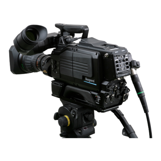
- Page 1 HDK-65C ( FA-97 ) HIGH DEFINITION CAMERA SYSTEM OPERATION MANUAL...
- Page 3 OUTLINE HDK-65C NAME and FUNCTION (FA-97) INSTALLATION and CONNECTION HIGH DEFINITION CAMERA SYSTEM OPERATION OPERATION MANUAL CAMERA SETTINGS and ADJUSTMENT TROUBLE SHOOTING and MAINTENANCE SPECIFICATIONS CHANGING INFORMATION 1501 1st Edition (U)
- Page 4 Copyright © 2015 Ikegami Tsushinki Co., Ltd. We reserve the copyright on the software we create. No part of this publication may be modified or reproduced in any form, or by any means, without prior written permission from Ikegami Tsushinki Co., Ltd.
-
Page 5: Products Conforming To Rohs Directive
80% and less than 85% by weight 14. Lead in solders to complete a viable electrical connection between semiconductor die and carrier within integrated circuit Flip Chip packages 15. Decabrominated diphenyl ether (Deca-BDE) in polymeric applications HDK-65C 1501 VER1 (U) -
Page 6: Maintenance Of Products Conforming To Rohs Directive
- If the customer mixed the lead-solder with the main body wiring or the circuit board, it becomes guarantee off the subject. Ikegami doesn't guarantee to do the repair work. Because the solder polluted with lead cannot be removed. 3. Parts Be sure to use parts conforming to RoHS directive. -
Page 7: Information To The User
The CE mark means that the following products will meet the Directive 2004/108/EC,2006/95/EC and the Standards EN55103-1 E4-E5, EN55103-2 E4-E5 (for EMC), EN60950-1 (for LVD). For European customer. 3. Rated current value of the camera when HDK-65C are used for the system operation is shown below. Rated current value · HDK-65C AC220V (50-60Hz) : 0.6A... -
Page 8: Safety Precautions
Indicates that mishandling may cause an electric shock. Indicates that mishandling may cause a fire. Indicates that mishandling may cause injury. The following symbol is used to indicate other precautions to prevent damage or hazard from occurring: Indicates prohibited action. HDK-65C 1501 VER1 (U) - Page 9 - In direct sunlight for a long time, or near a heater - High humidity or dusty - Exposed to water or other liquid - Strong vibration or shock - Strong magnetic field or radio waves - lightning - In rain without the rain cover HDK-65C 1501 VER1 (U)
- Page 10 Wrong usage of batteries may cause liquid leak, explosion, and heat, and at worst injury or fire. When changing or discarding a battery, please contact Ikegami's sales and service centers. Risk of explosion if battery is replaced by an incorrect type. Dispose of used batteries according to the instructions.
- Page 11 Fiber Optic Cable - When connecting a fiber optic cable to a fiber connector, anchor the fiber optic cable with a cable clamp. CAMERA CABLE Clamp CAMERA CABLE Clamp (optional) RET-1 RET-2 BREAKER /MIC Optical Fiber Cable HDK-65C 1501 VER1 (U)
- Page 12 This product includes parts that wear out and have a limited life even in proper use or storage. Therefore, regular maintenance is recommended to extend the life and safe use of this product for a long time. Please contact Ikegami's sales and service centers for the regular maintenance and repair of our products.
-
Page 13: How To Read The Operation Manual
HOW TO READ THE OPERATION MANUAL HOW TO READ THE OPERATION MANUAL This page explains general notes on reading the HDK-65C Operation Manual, and the symbols and notations used in the manual. ■ Notes on the Manual - This manual is written for readers with a basic knowledge of handling broadcast cameras. - Page 14 ■ Structure of Operation Manual HDK-65C High Definition Camera System Operation Manual is intended to both safely and smoothly operate the HDK-65C. The Operation Manual consists of seven chapters. By reading it in sequence, you can smoothly perform a series of steps, from connection to operation.
-
Page 15: Table Of Contents
Connection Example for Each Operating System ......33 HDK-65C 1501 VER1 (U) - Page 16 Reset the Breaker ....112 Chapter 7 SPECIFICATIONS HDK-65C Specifications ....115 External Dimensions Diagram ...117 External Connections .
-
Page 17: Chapter 1 Outline
OUTLINE... - Page 18 HDK-65C 1501 VER1 (U)
-
Page 19: Features Of This Product
■ Super KNEE Includes a super KNEE function which produces the KNEE process with less saturation loss, and without changing the hue of the highlighted parts. Produces a more natural highlight appearance, rather than washing out the color. HDK-65C 1501 VER1 (U) -
Page 20: Pursuit For Superb Operation And Ease Of Use
Employs a rotating fiber camera cable connector. This enables studio shooting and field shooting at various angles. ■ Return Switch A switch to choose RET-1 or RET-2 is also equipped on the handle grip of the camera to easily switch when low angle shooting. HDK-65C 1501 VER1 (U) -
Page 21: Peripheral Equipment To Support A Wide Range Of Purposes
FILE that is set at shipment according to environment or shooting conditions where the and FACTORY SET FILE. camera system is used. This enables to initialize the camera status quickly even though the settings are changed due to causes such as wrong operation of the menu. HDK-65C 1501 VER1 (U) -
Page 22: Operating Systems
CSU (Camera Select Unit) Used when controlling multiple cameras. With using a MCP, one CSU can control up to 8 cameras, and contains terminals through which video is output on the monitor from the selected camera. HDK-65C 1501 VER1 (U) - Page 23 CSU-1 CCU-8 CCU-8 PM, WFM, COMM CCU-9 CCU-9 CSU-2 CCU-16 CCU-16 CCU-17 CCU-17 CSU-3 CCU-24 CCU-24 CCU-25 CCU-25 CSU-4 CCU-32 CCU-32 ■ Example of VTR Location Configuration (Minimum Configuration of Camera, VTR, and PM) Camera Head HDK-65C 1501 VER1 (U)
- Page 24 75Ω network connector at the same CPH-200 termination BSH-200 time in this configuration. CCU-2 CCU-3 CP cable Coaxial cable OCP-200 75Ω termination ARC1 CP cable ARC2 CCU-4 ARC1 Coaxial cable ARC2 CPH-200 ARC3 75Ω termination CCU-5 BSH-200 CCU-6 HDK-65C 1501 VER1 (U)
-
Page 25: Connection Diagram
OUTLINE... -
Page 27: Chapter 2 Name And Function
NAME and FUNCTION... - Page 28 HDK-65C 1501 VER1 (U)
-
Page 29: Camera And Viewfinder
⑦ POWER switch FILTER HEAD switch ⑭ ⑮ CC FILTER switch SHUTT/SUP-V switch ⑬ ⑯ ND FILTER switch ⑰ FILTER local indicator GAIN SELECT switch OUTPUT SELECT switch ⑳ ⑱ AWB/ABB switch ⑲ AWB SELECT switch HDK-65C 1501 VER1 (U) - Page 30 ⑪ INCOM PHONE control knob Controls the volume of the intercom when the INCOM FRONT VR SELECT switch on the rear of the camera is set to "ENG" or "PROD". ⑫ Switch control panel cover Protects the switch control panel. HDK-65C 1501 VER1 (U)
- Page 31 ABB : By setting this switch to the ABB position, automatic adjustment of black balance starts. The adjusted value is stored in memory. If the switch is set to ABB continuously even during ABB activation, automatic adjustment of black shading starts. HDK-65C 1501 VER1 (U)
- Page 32 M : Gain value set by the menu is obtained. The set value is -3dB, +3dB, +6dB, +9dB H : Gain value set by the menu is obtained. The set value is +3dB, +6dB, +9dB, +12dB. HDK-65C 1501 VER1 (U)
-
Page 33: Camera Left View
② VF connector VF CONNECTOR LOCK button ③ ① Shoulder belt hook ⑩ CAMERA CABLE clamp ④ VF CABLE clamp CAMERA connector ⑨ RET-1 button ⑥ ⑦ Breaker Memory Card Slot ⑪ ⑤ RET-2/MIC button ⑧ MIC CABLE clamp HDK-65C 1501 VER1 (U) - Page 34 When storing or retrieving data, the access indicator on the side of the the slot is lit. Do not remove the card if the access indicator is lit. This could not only destroy the data on the card but also destroy camera data. HDK-65C 1501 VER1 (U)
-
Page 35: Camera Front View
2.1 Camera and Viewfinder Camera Front View Cable clamp ⑨ ② LENS LOCK lever ① Lens mount ⑦ P.FUNC switch ⑥ VF CHAR button LENS connector ⑧ ⑤ ROTARY PULSE switch ④ SET button MIC button ③ HDK-65C 1501 VER1 (U) - Page 36 [Lens Connector]" for the pin functions of the lens connector. ⑧ LENS connector Connects a 12-pin lens cable. It is compatible with both BTA lens mounting method. ⑨ Cable clamp Secures the microphone cable and lens cable (pigtail cable). HDK-65C 1501 VER1 (U)
-
Page 37: Camera Rear View
MIC-1 POWER switch ⑳ ⑭ REMOTE connector MIC-2 POWER switch ⑲ ⑮ DC IN connector MIC-1 connector ⑱ ⑯ System expansion connector ⑰ MIC-2 connector MON SDI connector HD TRUNK IN connector (Option) Q-TV2 connector (Option) HDK-65C 1501 VER1 (U) - Page 38 A multi-connector for input/output signals including GREEN/RED TALLY control output Note: signals, RET-1/RET-2 control input signals, and RS-422 data control signals. RS-422 data trunk line is optional. Reference: See "7. SPECIFICATIONS [I/O Connector]" for the pin functions of the I/O connector. HDK-65C 1501 VER1 (U)
- Page 39 Q-TV/GL, MON OUT SELECT switch Selects the type of signal which is output from the Q-TV/GL, MON OUT connector. ○ INCOM-1 connector Connects the producer's intercom headset. It is compatible with XLR series or 110-type phone jack connectors. HDK-65C 1501 VER1 (U)
- Page 40 (1.5G x2) transmission from the camera head to the CCU. And the second 1.5G video can be transmitted to the CCU as a video trunk channel. ○ Q-TV2 connector (option) Outputs the Q-TV signals. The Q-TV signal output function only responds during BS operation. HDK-65C 1501 VER1 (U)
-
Page 41: Viewfinder (Vf421Hd)
⑪ MIC HOLDER attaching mount Escutcheon Front View label display ⑨ FRONT TALLY Lamp BATT PEAKING CONTRAST BRIGHT ZEBRA TALLY HIGH PEAKING knob ④ ⑧ TALLY switch CONTRAST knob ⑤ ⑦ ZEBRA switch BRIGHTNESS knob ⑥ HDK-65C 1501 VER1 (U) - Page 42 R TALLY is input to various expansion devices. Since the REAR TALLY lamp serves as the switch, it can be turned ON/OFF by sliding. ⑪ MIC HOLDER attaching mount Attaches an external microphone holder. HDK-65C 1501 VER1 (U)
-
Page 43: Displays In The Viewfinder
The zebra indicator is turned ON or OFF using the ZEBRA switch on the front of the viewfinder. Reference: See "5. CAMERA SETTINGS and ADJUSTMENT [Menu Configuration and content]" for how to set the zebra signal. HDK-65C 1501 VER1 (U) -
Page 44: Side Mask Function
1/100 ⑰ Shutter speed/focus indicator/ Zoom indicator ⑱ Digital Extender ⑯ AWB memory channel ⑩ OPT level ⑫ GAIN UP value ⑮ Operational priority for filter control ⑭ ND, CC filter indication ⑨ SKIN DTL ON/OFF HDK-65C 1501 VER1 (U) - Page 45 ⑬ Temperature warning TEMP!! ■ Auto Setup Display ② Auto setup function ABB ⑤ Execution result of auto setup O K BLKSET ⑥ Adjustment item of auto setup ■ Return Video Channel Display ⑲ Return video input channel RET−1 HDK-65C 1501 VER1 (U)
- Page 46 (Selection between A-ch and B-ch is made by the AWB SELECT switch.) The AWB color temperature is also displayed when the FILTER switch is operated. ⑨ SKIN DTL ON/OFF "SK" is displayed when the SKIN DTL function is ON. HDK-65C 1501 VER1 (U)
-
Page 47: Installation And Connection
INSTALLATION and CONNECTION... - Page 48 HDK-65C 1501 VER1 (U)
-
Page 49: Preparation
Connection Example for Each Operating System Not only can the HDK-65C be used stand-alone for video location operation, but it can also be used in various operating systems in studio and in field as a system camera in combination with peripheral equipment such as the CCU. - Page 50 HDK-65C 1501 VER1 (U)
- Page 51 INSTALLATION and CONNECTION...
- Page 53 INSTALLATION and CONNECTION...
-
Page 55: Camera And Peripheral Installation And Connection
Camera right view Insert the rear wedge of the camera into the groove of the tripod mount plate and move it backward slightly. Camera rear wedge Camera front wedge ④ Insert the camera wedges. Mount plate Tripod HDK-65C 1501 VER1 (U) - Page 56 Press the red button on the lock lever to unlock the camera. Be sure to hold the handle while pressing the button to prevent the camera from falling. Lift the camera and remove the wedges from the tripod mount plate. HDK-65C 1501 VER1 (U)
-
Page 57: Mounting And Removing The Lens
Be sure to place the camera on a tripod or on a flat, level, stable surface when you mount the lens. The lens can be mounted to the HDK-65C either by BTA mounting method. Before proceeding any further, remove the lens cap by pushing up the lens lock lever. - Page 58 Support the lens with your hand to prevent it from Counter-clockwise to the end stop and remove the lens. falling. Remove the pigtail cable from the cable clamps. Put the lens cap on to protect the lens from scratches. HDK-65C 1501 VER1 (U)
-
Page 59: Mounting And Removing The Viewfinder
Align the pins on the viewfinder cable with the viewfinder connector and push until the connector lock button clicks. CAUTION: Be careful not to catch your fingers in the lock lever or guide-rail when attaching the viewfinder. Take caution to avoid injury. HDK-65C 1501 VER1 (U) - Page 60 Rotate the eyepiece in the direction shown in the figure. Rotate the eyepiece until it clicks. You will hear a click sound when the eyepiece is locked to the viewfinder. mark HDK-65C 1501 VER1 (U)
-
Page 61: Attaching The Microphone
Be sure to set the power supply method for the microphone before the power is supplied to the camera. See "4. OPERATION [4.2 Switch Position Check]" for how to select the power supply. For details on the microphone, refer to the instructions accompanying the microphone to be used. HDK-65C 1501 VER1 (U) -
Page 62: Connecting The Headset
3.2 Camera and Peripheral Installation and Connection Connecting the Headset Two intercom lines (1 and 2) can be connected to the HDK-65C. Please select the engineer intercom or producer intercom depending on the use. This section explains how to connect the engineer intercom to the camera. -
Page 63: Power Connection
Connect the DC OUT connector on the POWER and the DC IN connector on the camera via the DC POWER cable. Turn the POWER switch on the POWER ON. The POWER indicator on the POWER will light. HDK-65C 1501 VER1 (U) -
Page 64: Power Supply From Ccu
This completes the procedure for connecting power from the CCU-970 to the camera. There are two methods of supplying power to the camera in this state: - When operating the camera power source from the CCU. - When operating the camera power source from OCP (remote control). HDK-65C 1501 VER1 (U) - Page 65 To turn on the CCU MAIN POWER switch just after the switch is turned off, wait one or more seconds before you turn on the power. Repeating the on/off operation within one second activates the protector. When the protector is activated, turn on the CCU MAIN POWER switch after five or more seconds later. HDK-65C 1501 VER1 (U)
- Page 66 Power is supplied to the camera. CAM PWR switch Note: When the CAM POWER switch on the OCP is turned "ON/OFF", only power supply to the camera is turned "ON/OFF", and the CCU power is not turned "ON/OFF". HDK-65C 1501 VER1 (U)
-
Page 67: Monitor Connection
3.4 Monitor Connection 3.4 Monitor Connection This section explains how to connect the HDK-65C to the monitor. Connecting Camera and Monitor There are three connectors on the rear of the camera to output various video signals. The type of video signal output from each connector is different. -
Page 68: Ccu Connection
3.5 CCU Connection 3.5 CCU Connection This section explains how to connect the HDK-65C to the CCU. CCU-970 is used here as an example. Two types of fiber cables are available in different shapes. - Fiber cable (2-core single mode) : Diameter 9.2mm or 16mm, Maximum length 3000m (when CCU-970 is used) - Page 69 Remove the cable from the CCU-970 while pushing the unlocking ring of the CAMERA connector on the rear of CCU-970. If the connector tip is locked, the fiber cable will not be removed. If it is locked, push the fiber cable toward the CAMERA connector, and then remove as described above. HDK-65C 1501 VER1 (U)
- Page 70 HDK-65C 1501 VER1 (U)
-
Page 71: Chapter 4 Operation
OPERATION... - Page 72 HDK-65C 1501 VER1 (U)
-
Page 73: Operating Procedures
4.1 Operating Procedures 4.1 Operating Procedures This chapter explains how to operate the HDK-65C camera. ■ Initial Operation Check ―――――――――――――― When you use the camera for the first time after purchase, ensure that it wor s properly. ◆ 4.2 Switch Position Check 4.3 Turning ON Power... -
Page 74: Switch Position Check
+48V Supplies +48V Phantom power Reference: For details on the microphone, refer to the instructions accompanying the microphone to be used. HDK-65C 1501 VER1 (U) - Page 75 Switch Position Check ■ Viewfinder - TALLY switch : LOW - ZEBRA switch : ON TALLY switch ZEBRA switch HDK-65C 1501 VER1 (U)
-
Page 76: Turning On Power
: Lights when the fiber cable is not connected or there is an "open" in the fiber cable. SHORT (red) : Lights when a short circuit occurs in the fiber cable due to a cause such as water. HDK-65C 1501 VER1 (U) - Page 77 It is possible to use the OCP to control the camera power source. When the CAM POWER switch of OCP has been turned ON/OFF, only the camera power supply is turned ON/OFF. The CCU power supply is not turned ON/OFF. HDK-65C 1501 VER1 (U)
-
Page 78: Viewfinder Adjustment
You can select the display mode for various markers and characters displayed in the viewfinder. Set the display mode suitable for the conditions in which the camera is used. Reference: The display mode is set by the menu. See "5. CAMERA SETTINGS and ADJUSTMENT [Menu Configuration and content]". HDK-65C 1501 VER1 (U) -
Page 79: Output Signal Check
LCD panel Note: When no color bar signal is not displayed on the SDTV signal while you use MCP-200 and press the "Y" button of the MONITOR SELECT buttons, refer to the operation manual for MCP-200. HDK-65C 1501 VER1 (U) -
Page 80: Test Pulse (Cal Signal) Check
RANGE SENS WFM/PM /Mix HEAD CLS OPEN ±1 ±2 CABLE OPEN SHORT ALARM CALL PREVIEW "R", "G", "B", "Y", "SEQ" LCD panel External Chart Check Shoot an external chart and ensure that the image is normal. HDK-65C 1501 VER1 (U) -
Page 81: Auto Setup
Auto setup can be activated from the camera, OCP, and MCP. See the table in the next page for which device can activate which auto setup function. Reference: For how to execute auto setup from the OCP/MCP, refer to the relevant operation manual. HDK-65C 1501 VER1 (U) - Page 82 - EXT (external reference) of REF is the value set by the reference set function. - The item for G channel with a circle only works when it is set with a diascope (lens option). When you use the external chart, set G channel to 100% level by IRIS. HDK-65C 1501 VER1 (U)
-
Page 83: Full Auto Setup And Level Auto Setup
- Press the SETUP button in the function switch part. - Press the AUTO SETUP button on the LCD. - Press the Full or Level button on the LCD. - Press the Start button on the LCD. HDK-65C 1501 VER1 (U) -
Page 84: Full Quick Auto Setup And Quick Auto Setup
When the priority is given to the camera, an asterisk (*) is displayed in the viewfinder. Shoot a subject which contains something white. Make sure that the white subject fills at least 10% of the screen. HDK-65C 1501 VER1 (U) - Page 85 If the control knob is not at the center position, the control range may be biased. Note: To activate the auto white balance from an OCP, press the AWB button in the camera function operation part. To activate it from an MCP, press the AWB button on the LCD. HDK-65C 1501 VER1 (U)
-
Page 86: Auto Black Balance
Note: To activate the auto black balance from an OCP, press the ABB button in the camera function operation part. To activate it from an MCP, press the ABB button on ABB the LCD. O K HDK-65C 1501 VER1 (U) -
Page 87: Auto Black Shading
- To activate the auto black shading from an OCP, press the ABB button in the camera function operation part. - To activate it from an MCP, press the Quick button A.BLK SHADE on the LCD, then press the ABB button. BLACK SHADE A.BLK SET O K HDK-65C 1501 VER1 (U) -
Page 88: Preparation For Shooting In Particular Environment
When shooting where the electromagnetic field is excessively Rainproof cover strong, such as in airports, military bases or transmitting stations, completely shield the camera by thoroughly covering it with aluminum foil. It is necessary to take the same measure for other devices. HDK-65C 1501 VER1 (U) -
Page 89: Camera Settings And Adjustment
CAMERA SETTINGS and ADJUSTMENT... - Page 90 HDK-65C 1501 VER1 (U)
-
Page 91: Settings Using Switches On The Camera
Set the INCOM FRONT VR SELECT switch on the rear of the camera to INCOM-1 or INCOM-2. Turn the INCOM PHONE control knob on the right side of the camera to adjust the volume. CAUTION: Be sure to adjust the volume to the appropriate level while listening to sound through the headset. HDK-65C 1501 VER1 (U) -
Page 92: Selecting Shutter Speed
(when SEMI REMOTE MODE is set to "OFF"). For details on how to operate the various remote controllers, refer to the instruction manuals attached to the remote controllers. Camera right view Camera front view (Switch control panel) CHAR P.FUNC PUSH MENU Rotary pulse switch SHUTT/SUP-V switch HDK-65C 1501 VER1 (U) - Page 93 - Set the SHUTT/SUP-V switch to OFF. The displayed speed is maintained until the switch is set to ON. The shutter speed is validated when the switch is set to ON. ■ To cancel the Shutter Speed Set the SHUTT/SUP-V switch to OFF. HDK-65C 1501 VER1 (U)
-
Page 94: Enhancing The Vertical Resolution (Super-V Function)
Each time the SHUTT/SUP-V switch is pressed to the SET position, the mode switches in the order of preset shutter, variable shutter and SUPER-V. Select "SUPER-V". Note: The flashing stops automatically in approximately 3 seconds after the setting operation ends. Press the SET button. ■ To Cancel the Super-V Function Set the SHUTT/SUP-V switch to OFF. HDK-65C 1501 VER1 (U) -
Page 95: Switching The Gain
For details on how to operate the various remote controllers, refer to the instruction manuals attached to the remote controllers. Use the GAIN (dB) on the remote controller to switch the setting according to the conditions. HDK-65C 1501 VER1 (U) -
Page 96: Allocating Functions To The P.func Switch
Turns ON/OFF scene file 7 SCENE-8 Turns ON/OFF scene file 8 Set the P.FUNC switch to ON. The allocated function is now activated. Note: Setting the P.FUNC switch to OFF will turn the allocated function OFF. HDK-65C 1501 VER1 (U) -
Page 97: Screen Detail Enhancement (Dtl)
Functions to the P.FUNC Switch]" for how to allocate the function. ■ Activating from the Remote Controller Reference: For details on how to operate the various remote controllers, refer to the instruction manuals attached to the remote controllers. HDK-65C 1501 VER1 (U) -
Page 98: Settings From The Menu
This section explains how to display the simple menu in the viewfinder and monitor. *** MENU *** Press the SET button while holding down the VF CHAR button on the front of the camera. VF DISPLAY VF DTL The main menu appears in the viewfinder and monitor. RETURN SELECT MODE FILTER SERVO MODE COLOR VF MODE INFORMATION HDK-65C 1501 VER1 (U) - Page 99 If the SET button is not pressed after selecting a value in the mode selection column, the change may be canceled. Note: - To return to the main menu, select " " and press the SET button. - The scroll guide is displayed on the submenu containing multiple items. HDK-65C 1501 VER1 (U)
- Page 100 This section explains how to exit the main menu/submenu in the viewfinder or monitor. Press the VF CHAR button on the front of the camera. The main menu/submenu disappears. Note: The menu in SE operation terminates when the MENU switch is turned OFF. HDK-65C 1501 VER1 (U)
-
Page 101: Menu Configuration And Content
The MIC2 gain is changed stepwise. ― MIC2 STEP -50dB, -60dB Fine adjustment of the MIC2 gain. The gain decreases about -100 to 100 MIC2 FINE -8 dB with -100, and increases about +8 dB with +100. HDK-65C 1501 VER1 (U) - Page 102 *1 : It is possible to determine when loading MENU DATA from the SD CARD whether to read the entire MENU or to read only items related to VF. The setting of an item having a checkmark is read. HDK-65C 1501 VER1 (U)
- Page 103 +100. Can only be set during self-operation. TIME SETTING HH : MM : SS ― TIME Sets the time and date when saving the file to the memory card. YY / MM / DD DATE (YY/MM/DD) HDK-65C 1501 VER1 (U)
- Page 104 GAIN changing OFF, ON switch, AWB changing switch, output changing switch and SEMI REMOTE MODE SHUTT/SUP-V switch on the right side of the camera. In this case, control on the remote controller side is not possible. HDK-65C 1501 VER1 (U)
- Page 105 AWB, or ABB to create reference fi le. FULL : Sets the reference values for all auto setup items, REFERENCE SET except AWB convergence value. AWB : Sets the user setting as AWB convergence value. ABB : Sets a reference value of pedestal. HDK-65C 1501 VER1 (U)
- Page 106 TYPE3 : The compression rate of brightness is high. If the V filter of the DTL is ON, the resolution feeling in ON, OFF direction V diminishes, making it possible to obtain an DTL V FILTER image with less noise. HDK-65C 1501 VER1 (U)
- Page 107 : Initializes the state back to the initial factory ― FILE SELECT setting. READY, START, READY Executes initialization. LOAD START CANCEL *2 : CUSTOM GAMMA MODE - Loads the custom gamma data from SD card through the LOAD menu. HDK-65C 1501 VER1 (U)
- Page 108 - Use an illumination meter to adjust the light so that light is evenly distributed over the whole chart. Dip switch S11-4 On allows creation of a lens file, Off prohibits creation of new lens files. HDK-65C 1501 VER1 (U)
- Page 109 Lens files memorize a difference in level between lenses. If the lighting or chart is changed, it cannot tell whether it is the lighting error, chart error, or lens error. HDK-65C 1501 VER1 (U)
- Page 110 Turn the rotary pulse switch to switch the cursor (BB40X10 BCDE ) on "MANUAL" to "OFF", and press the SET button EXTENDER OFF to complete the lens file creation. Then, go to Step AUTO SEL OFF M④ FILE SET OFF LENS TYPE *** Switch the cursor on "MANUAL" to "OFF" LENS NO.1 and confirm. HDK-65C 1501 VER1 (U)
- Page 111 Select the target lens (AB40X10 ABCD ) The NO.5 lens set in "AUTO SEL" is selected here as number and confirm. EXTENDER OFF an example and the AUTO SEL NAME display part AUTO SEL OFF FILE SET OFF displays "AB40X10 ABCD". HDK-65C 1501 VER1 (U)
- Page 112 SET button. E⑧ (AB40X10 ABCD ) Position the cursor on The item changes to the edit mode and ( ) at both ends the part for displaying flash. the lens name to be edited and confirm. NOW CONNECTED LENS (AB40X10 ABCD ) HDK-65C 1501 VER1 (U)
- Page 113 3. "AUTO SEL NAME EDIT" is a function to edit the model name read through "AUTO READ". 4. This function is not available if the model name of the target serial lens has not been obtained through "AUTO READ". HDK-65C 1501 VER1 (U)
-
Page 114: Using The Memory Card
VF menu screen. When removing the memory card from the card slot, gently press the memory card until there is a clicking sound and then carefully remove the card. HDK-65C 1501 VER1 (U) - Page 115 [SAVING FILE] or while the access indicator is lighted, as data is being written to the memory card. Removing it at this time could damage the memory card data or the memory card itself. HDK-65C 1501 VER1 (U)
- Page 116 OVERWRITE NO Note: The images of the storage range for files are shown in the figure below. ALL FILE SNAPSHOT FILE Parameters for adjusting functions and ON/OFF state. SCENE FILE REFERENCE FILE (ABB/AWB) LENS FILE MENU FILE HDK-65C 1501 VER1 (U)
- Page 117 If changes as those listed below have been made in the file name stored to a PC, etc., it is not possible to display the file name normally. -If a file name with more than 8 characters has been set. -Using file names (kanji, kana, etc.) composed of characters other than half-size letters of the alphabet. HDK-65C 1501 VER1 (U)
- Page 118 NOT CAMERA DATA FILE. Not a camera data file. FILE OF DIFFERENT CAMERA. Different type of file. RELEVANT DATA IS NOT FOUND. Relevant data cannot be found. WIRTE ERROR Write error. READ ERROR Read error. ERROR Other error. HDK-65C 1501 VER1 (U)
-
Page 119: Trouble Shooting And Maintenance
TROUBLE SHOOTING and MAINTENANCE... - Page 120 HDK-65C 1501 VER1 (U)
-
Page 121: Alarm Lamp On The Ocp Or Mcp Flashes On And Off
HEAD CABLE CLS OPEN ±1 ±2 OPEN SHORT ALARM CALL PREVIEW ALARM indicator For the list of self diagnostic information of CCU, refer to the relevant operation manual. Perform the appropriate action referring to the list. HDK-65C 1501 VER1 (U) -
Page 122: Temp!!" Or "Fan!!" Appears On The Vf Screen
To prevent temperature increase inside the camera, cooling fans are provided at the top of the camera and fiber adaptor. For how to check which fan stops, See "5. CAMERA SETTINGS and ADJUSTMENT [Menu Configuration and content]". HDK-65C 1501 VER1 (U) -
Page 123: Initializing The Settings Of This Product
Press the SET button when the cursor PRESET FILE LOAD automatically moves to "LOAD START". FILE SELECT ENGINEER The cursor moves to the mode selection column and its ④ LOAD START READY display changes from "READY" to "START". Position the cursor on "LOAD START" and confirm. HDK-65C 1501 VER1 (U) - Page 124 file "COMPLETED" is selected in "FILE SELECT". displayed at the bottom of the screen. PRESET FILE LOAD FILE SELECT ENGINEER LOAD START START ⑥ CAMERA RESTART "CAMERA RESTART" is displayed at the bottom of the screen. HDK-65C 1501 VER1 (U)
-
Page 125: Cleaning Camera Connectors
Plug (male) Alignment sleeve Receptacle (female) Receptacle (female) Ferrule Ferrule Ferrule Receptacle (male) Receptacle (male) Ferrule ● Male and Female Camera Connectors Receptacle (male) CCU-970 rear Plug (female) RET-1 RET-2 BREAKER /MIC HDK-65C Receptacle (female) Plug (male) HDK-65C 1501 VER1 (U) - Page 126 Tighten the screw with a flat-blade screwdriver or a coin. Camera male connectors have no "top" regardless of whether they are receptacles or plugs. For male connectors, therefore, steps 1, 2, and 6 above are not required. HDK-65C 1501 VER1 (U)
- Page 127 The extractor is removed from the alignment sleeve. Camera male connectors have neither "top" nor "alignment sleeve" regardless of whether they are receptacles or plugs. For male connectors, therefore, steps 1 to 3 and 8 above are not required. HDK-65C 1501 VER1 (U)
-
Page 128: Reset The Breaker
In this case, reset the breaker as follows: Check that the camera's POWER switch is OFF. Push in the breaker on the left side of the camera. Breaker HDK-65C 1501 VER1 (U) -
Page 129: Chapter 7 Specifications
SPECIFICATIONS... - Page 130 HDK-65C 1501 VER1 (U)
-
Page 131: Hdk-65C Specifications
No condensation. 17 Ambient humidity FCC Class A 18 EMI Approx. W138.5×H270×D337 Not including projections. 19 External dimensions HDK-65C+FA-97 : 4.6 kg 2 Inch VF : 770 g 20 Weight 9 Inch VF : 2.1 kg Uses attachment. HDK-65C 1501 VER1 (U) - Page 132 4 Power cables 113Ω/Km per cable 5 Control cables ■ Applicable standards Safety Standards : CE / FCC ■ Use conditions Electrical environment : Usually a short life (Except electric field strength, magnetic field strength, etc.) HDK-65C 1501 VER1 (U)
-
Page 133: External Dimensions Diagram
7.2 External Dimensions Diagram 7.2 External Dimensions Diagram ■ Right View ±5 ±1 HDK-65C 1501 VER1 (U) - Page 134 7.2 External Dimensions Diagram ■ Left View ±3 ±1 ±5 HDK-65C 1501 VER1 (U)
- Page 135 7.2 External Dimensions Diagram ■ Front View ±3 138.5 HDK-65C 1501 VER1 (U)
- Page 136 7.2 External Dimensions Diagram ■ Rear View ±3 138.5 HDK-65C 1501 VER1 (U)
-
Page 137: External Connections
Cable side : HR10A-10P-12PC (12 pin male plug) Insertion Side [BTA Mount] Pin No. Name Function External Interface ① RET ON ② VTR TRIG ③ ④ IRIS SERVO ⑤ IRIS CONT ⑥ +12V LENS ⑦ IRIS FOLLOW HDK-65C 1501 VER1 (U) - Page 138 ZOOM FOLLOW FOCUS FOLLOW ⑪ LENS → CAMERA ⑫ CAMERA → LENS Numbers within parentheses are standard values in the conventional SDTV system of 2/3-inch camera lens. : camera <- lens OUT : camera -> lens HDK-65C 1501 VER1 (U)
- Page 139 +12V RET ⑫ ZEBRA ON ⑬ ZOOM POSI ⑭ ( +9V ) ⑮ COLOR ON ⑯ B VF VIDEO ⑰ B VF VIDEO RET ⑱ R VF VIDEO ⑲ R VF VIDEO RET ⑳ +12V RET HDK-65C 1501 VER1 (U)
- Page 140 Optical contact BS -> Camera ③ Control signal (H) BS -> Camera CONTROL (H) ④ CONTROL (C) Control signal (C) Camera -> BS ⑤ POWER (H) Power (H) supplied from BS ⑥ POWER (C) Power (C) supplied from BS HDK-65C 1501 VER1 (U)
- Page 141 Intercom microphone ④ TALK (H) Intercom microphone input (H) ⑤ COMM COMM GND terminal Intercom receiver R output (H) ⑥ LISTEN R (H) Receiver R Shield for Intercom receiver R output (H) ⑦ LISTEN R (C) HDK-65C 1501 VER1 (U)
- Page 142 Function External Interface ① TALK (C) Shield for intercom microphone input (H) ② TALK (H) Intercom microphone input Intercom microphone ③ LISTEN (C) Shield for LISTEN output (H) ④ LISTEN (H) LISTEN L output (H) Receiver HDK-65C 1501 VER1 (U)
- Page 143 ③ LISTEN L (C) Termination for when the plug was removed ④ TALK (C) Termination for when the plug was removed Intercom microphone input (H) ⑤ TALK (H) Intercom microphone Connect to T (tip) of plug HDK-65C 1501 VER1 (U)
- Page 144 Used to connect external power supply. Receptacle Camera head side : XLR-4-32-F512 Cable side : XLR-4-11C (4-pin female plug) or equivalent Insertion Side Pin No. Name Function External Interface ① +12 V RET ② ③ ④ +12 V IN HDK-65C 1501 VER1 (U)
- Page 145 DC +12V power supply to remote controller ○ + 12 V RET (REM) Ground for DC +12V power supply ○ REM LISTEN Intercom output from remote controller ○ REM TALK Intercom input to remote controller ○ HDK-65C 1501 VER1 (U)
- Page 146 (RTS - 2) ○ VF G / Y ○ ○ VF B /Pb VF R / Pr ○ N . C ○ N . C ○ N . C ○ N . C ○ N . C ○ HDK-65C 1501 VER1 (U)
- Page 147 N . C ○ AC 220 V (C) ○ N . C ○ M CLK ○ PS DATA 1 PS BUSY 1 ○ AD CLK ○ STBY PWR ○ R TALLY ○ ○ IRIS CONT ○ LENS COMM HDK-65C 1501 VER1 (U)
- Page 148 FOCUS FOLLOW SE ○ IRIS FOLLOW SE ○ ○ ZOOM FOLLOW SE N . C ○ N . C ○ N . C ○ N . C ○ N . C ○ N . C ○ HDK-65C 1501 VER1 (U)
- Page 149 ⑫ DC OUT Connector ■ Receptacle Camera head side : PRC05-R3F Cable side : PRC05-P3M Insertion Side Pin No. Name Function External Interface + 12 V ○ + 12 V RET ○ N . C ○ HDK-65C 1501 VER1 (U)
-
Page 150: Scene File
7.4 Scene File 7.4 Scene File ■ Save condition of a HDK-65C scene file BSF-55 Item Save Data SELF DTL CONT HEAD GAIN -6dB to +18dB CAMERA CAMERA GAMMA OFF/0.35/0.40/0.45 CAMERA CAMERA NORMAL, CINE1 to 2, GAMMA TYPE CAMERA CAMERA... -
Page 151: Changing Informatio
CHANGING INFORMATION This chapter contains the revision information of user-specific specification or design change requested by users or any changes done by Ikegami. Read by comparing this information with the main part of the operation manual. HDK-65C 1501 VER1 (U) - Page 152 HDK-65C 1501 VER1 (U)
- Page 153 Ikegami Tsushinki Co., Ltd. - All rights reserved. Reproduction or duplication, without permission of Ikegami Tsushinki Co., Ltd. of editorial or pictorial content in whole or in part, in any manner, is prohibited. - Specifications and design are subject to change without prior notice.
- Page 156 Ikegami Tsushinki Co., Ltd. 5-6-16, Ikegami, Ohta-ku, Tokyo, 146-8567, Japan Phone : +81-(0)3-5700-4114 Fax : +81-(0)3-5748-2200 E-Mail : info_e@ikegami.co.jp : http://www.ikegami.co.jp/en/ Ikegami Electronics (U.S.A.),Inc. 37 Brook Avenue, Maywood, New Jersey 07607, U.S.A. Phone : +1-201-368-9171 Fax : +1-201-569-1626 E-Mail : engineering@ikegami.com, service@ikegami.com : http://www.ikegami.com...
Need help?
Do you have a question about the HDK-65C and is the answer not in the manual?
Questions and answers