
Related Manuals for Ikegami HDL-45E


Summary of Contents for Ikegami HDL-45E
- Page 1 ND FILTER ND FILTER 1. 100% 1. 100% 6.2% 6.2% 1.6% 1.6% Products conforming to RoHS directive HDL-45E/E1 3CCD Multiple-purpose HDTV Camera Operation Manual...
- Page 3 ND FILTER ND FILTER 1. 100% 1. 100% 6.2% 6.2% 1.6% 1.6% Products conforming to RoHS directive HDL-45E/E1 3CCD Multiple-purpose HDTV Camera Operation Manual 1108 1st Edition (U) (E)
- Page 4 Copyright © 2011 Ikegami Tsushinki Co., Ltd. We reserve the copyright on the software we create. No part of this publication may be modified or reproduced in any form, or by any means, without prior written permission from Ikegami Tsushinki Co., Ltd.
- Page 5 PRODUCTS CONFORMING TO RoHS DIRECTIVE PRODUCTS CONFORMING TO RoHS DIRECTIVE Following products described in this manual are products conforming to RoHS directive. ・HDL-45E HDTV Camera ・HDL-45E1 HDTV Camera Products conforming to RoHS directive include products that do not contain specified hazardous substances such as...
-
Page 6: Maintenance Of Products Conforming To Rohs Directive
· If the customer mixed the lead-solder with the main body wiring or the circuit board, it becomes guarantee off the subject. Ikegami doesn’t guarantee to do the repair work. Because the solder polluted with lead cannot be removed. 3. Parts... -
Page 7: Information To The User
Changes or modifications not expressly approved by the party responsible for compliance could void the user’s authority to operate the equipment. mark means The CE mark means that the following products will meet the Directives 2004/108/EC and standards EN55022, EN55024. · HDL-45E : HDTV CAMERA · HDL-45E1 : HDTV CAMERA... - Page 8 (Blank page)
-
Page 9: Notes On Using In Safety
NOTES ON USING IN SAFETY NOTES ON USING IN SAFETY The followings are for your safe use of this product. Please peruse them before you start using. 1. Notes on this manual (1) This manual is written assuming that readers have a basic knowledge of cameras, so the technical terms are not described here. - Page 10 This product includes parts that wear out and have a limited life even in proper use or storage. Therefore, regular maintenance is recommended to extend the life and safe use of this product for a long time. Please contact Ikegami’s sales and service centers...
-
Page 11: How To Use Operation Manual
HOW TO USE OPERATION MANUAL HOW TO USE OPERATION MANUAL This operation manual is intended to describe how to operate HDL-45E/E1 3CCD Multiple-purpose HDTV Camera (mentioned as HD Camera hereafter). This operation manual is written for people who have some basic knowledge and understanding of a television camera, so explanation of technical terms is omitted herein. - Page 12 (Blank page)
-
Page 13: Table Of Contents
CONTENTS - 1 HDL-45E/E1 OPERATION MANUAL (TABLE OF CONTENTS) PRODUCTS CONFORMING TO RoHS DIRECTIVE MAINTENANCE OF PRODUCTS CONFORMING TO RoHS DIRECTIVE INFORMATION TO THE USER NOTES ON USING IN SAFETY HOW TO USE OPERATION MANUAL OUTLINE ..........................FEATURES ..........................NAME and FUNCTION of EACH PART .................. - Page 14 (Blank page)
-
Page 15: Outline
• 14-bit A/D converter The HDL-45E/E1 uses 14-bit A/D converter to obtain picture with broad tonal range from dark part to highlighted part. In particular, more natural “black” can be reproduced with higher tone of the dark part to which gamma... - Page 16 ■ Multi Format Corresponding to the following formats. HDL-45E: 1080/59.94i, 1080/50i, 1080/29.97psF, 1080/25psF HDL-45E1: 1080/59.94i, 1080/50i, 1080/29.97psF, 1080/25psF, 1080/24psF, 1080/23.98psF ■ Digital Extender The screen center can be expanded by the digital process.
-
Page 17: Name And Function Of Each Part
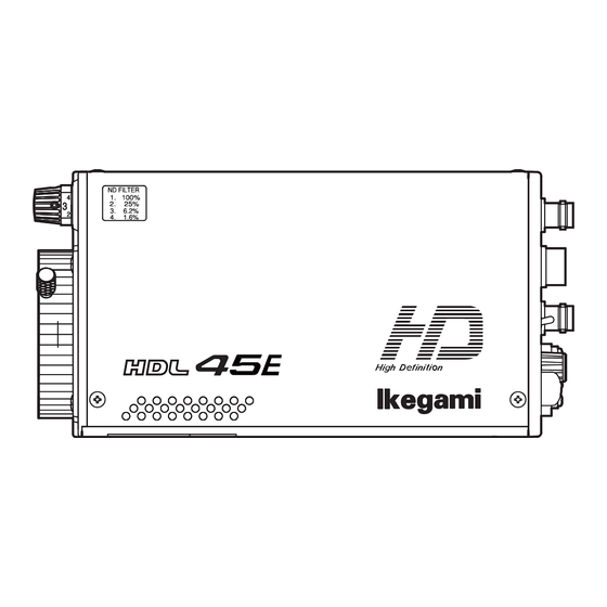
3. NAME and FUNCTION of EACH PART 3 - 1 3. NAME and FUNCTION of EACH PART 3.1 Front View / Right Side View / Bottom View ① Front View Right Side View ND FILTER ND FILTER 1. 100% 1. 100% 6.2% 6.2% 1.6%... -
Page 18: Rear View
3 - 2 3. NAME and FUNCTION of EACH PART 3.2 Rear View Rear View (Standard) ② ③ ① ④ ⑮ ⑤ ⑭ ⑥ ⑬ ⑫ ⑦ ⑪ ⑧ ⑨ ⑩ ⑪ POWER switch ⑥ G.L indicator ① FAN ⑫ POWER indicator ⑦... - Page 19 3. NAME and FUNCTION of EACH PART 3 - 3 : Black balance is adjusted automatically. By setting this switch to ABB position, the adjustment starts and the adjusted value is stored in memory. ⑩ MENU select switch (Rotary Encoder) Displays various information or control items on the monitor to show the camera status by pressing and holding this switch for more than one second.
- Page 20 (Blank page)
-
Page 21: Installation And Connections
4. INSTALLATION and CONNECTIONS 4 - 1 4. INSTALLATION and CONNECTIONS 4.1 System Setup Diagram Tripod Head System Control Box HDL-45E/E1 LENS ND FILTER ND FILTER SDI OUT Coaxial Cable (Max:100m) Zoom Lens 1. 100% 1. 100% 6.2% 6.2% 1.6% 1.6%... -
Page 22: Tripod Installation
4 - 2 4. INSTALLATION and CONNECTIONS Tripod Installation This section explains how to install the camera to the tripod. There are two ways to install the camera: one is to install it directly to the tripod and the other is to use the dedicated tripod mount plate (optionally available). -
Page 23: Lens Mounting
Be sure to push the pigtail cord until it clicks in to position. CAUTION Do not hold its lens because the mount may be unduly stressed and could bend or break. If the camera is supported grasping its lens, HDL-45E/E1 may easily fall and cause injury. -
Page 24: Connection Of Power Supply
4 - 4 4. INSTALLATION and CONNECTIONS Connection of Power Supply This section explains how to connect the power supply. Power supply source for the camera is +12V(allowable range : +11v to +16v). CAUTION Before connecting the power, verify that the POWER switch of the camera is turned “OFF.”... -
Page 25: Connection Of Monitor
4. INSTALLATION and CONNECTIONS 4 - 5 Connection of Monitor [ ANALOG output ] HD MONITOR (Color) VIDEO IN (G/B/R, Y/Pb/Pr) Camera rear view SDI OUT 75Ω Terminal COMM MON OUT Connector EXT SYNC WARNING GAIN POWER MENU DC IN DC IN Ferrite core Specified monitor cable... -
Page 26: Connection Of Remote Control Panel (Rcp-50B)
4 - 6 4. INSTALLATION and CONNECTIONS [ SDI output ] HD MONITOR (Color) HD SDI IN Camera rear view SDI OUT SDI OUT Connector COMM EXT SYNC WARNING GAIN POWER MENU Coax cable DC IN DC IN 1. With the coax cable, connect the SDI OUT connectors on the rear of the camera to the HDTV monitor. Also, perform 75 termination at HD MONITOR side. - Page 27 4. INSTALLATION and CONNECTIONS 4 - 7 Notice When RCP-50B is connected, following controls can be performed. • To use as a single remote controller, put it in the dedicated case • (optionally available). This enables direct connection to the camera. ON/OFF Control Items Control Analog Control Items...
-
Page 28: Connection Of External Sync Signal For Genlock
4 - 8 4. INSTALLATION and CONNECTIONS Connection of External SYNC Signal for Genlock Camera rear view EXT SYNC connector External SYNC signal External system 1. EXT SYNC connector is used to input the SYNC signal of the external system desired to be genlocked with the equipment. When the synchronizing the camera with the SYNC signal of external system, G.L indicator lights up green. -
Page 29: Operation
5. OPERATION 5 - 1 5. OPERATION Power Supply Injection After connecting the camera with the peripheral system components, set the POWER switch on the camera rear panel to “ON” and check to be sure that the POWER indicator comes on. Display the image output of the camera on the HDTV color monitor connected with the camera. -
Page 30: Auto White Balance (Awb)
5 - 2 5. OPERATION 5.2.2 Auto White Balance (AWB) [White balance adjustment] To create correct white balance images, it is necessary to perform white balance adjustment in accordance with the condition of place in which the subject is located. This condition is color temperature. -
Page 31: Camera Menu
5. OPERATION 5 - 3 Camera Menu Enter the menu by pressing and holding the MENU select switch located on the rear side of the HDL-45E/E1 for more than one second. Select an item in the menu to change the mode. - Page 32 5 - 4 5. OPERATION [MENU PAGE1] 1. “MENU PAGE1” contains eight items: “STEP GAIN,” “GAMMA SELECT,” “BLK PRS/STR,” “FILTER SELECT,” “CAL,” “FAN CTRL,” “MONITOR OUT,” and “AUTO BLK SEL.” 2. To select the desired item, turn and press the MENU select switch while the item is blinking. 3.
- Page 33 5. OPERATION 5 - 5 GAMMA SELECT QUIT MODE NORMAL (NORMAL, CINE1, CINE2) STEP 0.45 (0.45, 0.40, 0.35, OFF) MODE : Switches gamma type. NORMAL : Normal gamma CINE1 : CINE gamma type1 CINE2 : CINE gamma type2 STEP : Switches gamma step. Notice When MODE is switched to CINE1 and CINE2, KNEE_POINT and KNEE_SLOPE change with the gamma curve.
- Page 34 5 - 6 5. OPERATION [MENU PAGE2] 1. “MENU PAGE2” contains eight items: “GAIN,” “GAMMA,” “FLARE,” “PED,” “WHITE SHADE,” “WHITE CLIP,” “DTL,” and “H PHASE CONTROL.” 2. To select the desired item, turn and press the MENU select switch while the item is blinking. The sub menu screen of the selected item is displayed.
- Page 35 5. OPERATION 5 - 7 ■ GAMMA If the MENU select switch is pressed while any of “M,” “B,” or “R” is blinking, the value below it can be changed. Selecting “M CLR” makes the system to be set back to the factory setup.
- Page 36 5 - 8 5. OPERATION ■ WHITE SHADE 1. WHITE SHADE contains six items: “R CH H,” “R CH V,” “G CH H,” “G CH V,” “B CH H,” and “B CH V.” 2. To select the desired item, turn and press the MENU select switch while the item is blinking. The under sub menu screen of the selected item is displayed, as shown below.
- Page 37 5. OPERATION 5 - 9 ● G CH H If the MENU select switch is G CH H pressed while any of “H SAW” or “H PARA” is blinking, the value below it can be changed. Selecting “M CLR” makes the system to be set back to the factory setup.
- Page 38 5 - 10 5. OPERATION ■ WHITE CLIP If the MENU select switch is pressed while any of “G,” “B,” or “R” is blinking, the value be- low it can be changed. Selecting “M CLR” makes the system to be set back to the WHITE CLIP factory setup.
- Page 39 5. OPERATION 5 - 11 [MENU PAGE3] 1. “MENU PAGE3” contains eight items: “LOW/MID/HIGH GAIN MODE,” “SHUTTER,” “LENS SELECT,” “DIGITAL EXTENDER,” “PIX ADD SELECT,” “H REVERSE,” “AVC SETUP,” and “ATW SETUP.” 2. To select the desired item, turn and press the MENU select switch while the item is blinking. The sub menu screen of the selected item is displayed.
- Page 40 5 - 12 5. OPERATION ■ LOW/MID/HIGH GAIN MODE When the MENU select switch is LOW/MID/HIGH GAIN MODE pressed on the item to be set, the value on the right blinks. Keeping this QUIT state, turn the MENU select switch to LOW GAIN set the value (-6dB to +54dB).
- Page 41 5. OPERATION 5 - 13 ■ LENS SELECT LENS SELECT QUIT NUMBER NO. 1 NAME EXTENDER AUTO SEL FILE SET NUMBER : OFF: No lens file is registered. No.1 to No.8: Indicates the lens file number. NAME ( ) : Manually enter a file name for each lens file. ) : Displays the model name automatically obtained from the lens when a serial-interface-capable lens is used.
- Page 42 5 - 14 5. OPERATION 5. Turn the MENU select switch to select the desired character and press it. One character is set for a file name. Be sure to use 12 characters for a file name. Use blanks (□) if a file name is shorter. The file name setting mode cannot be completed if the file name has 11 characters or less.
- Page 43 5. OPERATION 5 - 15 1. Connect the remote control panel. 2. On “MENU PAGE3,” turn the MENU select switch to select “LENS SELECT” and press it. The sub menu of “LENS SELECT” is displayed. 3. Turn the MENU select switch to select “NUMBER” and the desired lens file number and press it. Select No.2 or later since the factory set data is set for No.1.
- Page 44 5 - 16 5. OPERATION [Editing lens file name] The “AUTO SELECT NAME EDIT” (the edit of lens name used for the lens file auto selection) can be operated by the following procedure. 1. Sets the blinking cursor to “NUMBER” and press “SET.” LENS SELECT 2.
- Page 45 5. OPERATION 5 - 17 ● About AUTO SEL NAME EDIT display AUTO SEL NAME EDIT QUIT AUTO SEL NAME EDIT (AB40X10ABCD Display part of the lens name to edit Displays the model name of the lens to edit. NOW CONNECTED LENS (AB40X10ABCD Display part of the lens name to connect Displays the model name of the lens...
- Page 46 5 - 18 5. OPERATION ■ DIGITAL EXTENDER Turns on/off the digital extender. DIGITAL EXTENDER (OFF, ON) QUIT Sets the magnification of the digital DIGITAL EXTENDER extender. However, the resolution MAGNIFICANT decreases when the maginification DTL GAIN&FRQ SET increases. (x1.5, x2, x3, x4, x6, x8, x10) (Set it to the magnification corresponding to the necessary resolution.)
- Page 47 5. OPERATION 5 - 19 x1.5 GAIN ; Sets the DTL gain at the X1.5 magnification. FREQ ; Sets the boost frequency at the FREQ; X1.5. x2.0 GAIN ; Sets the DTL gain at the X2.0 magnification. FREQ ; Sets the boost frequency at the FREQ; X2.0. x3.0 GAIN ;...
- Page 48 5 - 20 5. OPERATION [MENU PAGE4] 1. “MENU PAGE4” contains six items: “AUTO SETUP MODE,” “AUTO IRIS SET,” “AUTO DPC,” “KNEE,” “EXT-ND FILT LINK,” and “SYSTEM MODE.” 2. To select the desired item, turn and press the MENU switch while the item is blinking. The sub menu screen of the selected item is displayed.
- Page 49 5. OPERATION 5 - 21 ■ AUTO SETUP AUTO SETUP MODE QUIT AWB WITH A.IRIS (OFF, ON) AWB DETECT AREA WIDE (WIDE, SPOT) AWB MARKER (OFF, ON) AWB REFERENCE (OFF, ON) REFERENCE SET (ABB, AWB) AWB CC CONTROL (OFF, ON) (ABS, APS, ABS+APS) BLACK BALANCE ABS+APS...
- Page 50 5 - 22 5. OPERATION [AWB CC CONTROL] Sets the mode for which the ECC filter is automatically switched when AWB is performed. • ON: The ECC filter is automatically switched. • OFF: The ECC filter is not automatically switched. Notice AWB CC CONTROL is the function to perform AWB again by switching the ECC filter automatically when the color temperature of the subject does not fit with the ECC...
- Page 51 5. OPERATION 5 - 23 ■ AUTO DPC AUTO DPC QUIT (OFF, ON) DETECT MODE WHT+BLK (WHITE, BLACK, WHT+BLK) SAMPLE AREA SET AUTO DPC (OK, CANCEL) DPC EFFECT CHK DPC CLEAR (OK, CANCEL) : ON: Sets defect correction to on. OFF: Sets defect correction to off.
- Page 52 5 - 24 5. OPERATION 9. When “DPC DATA: OK” or “DPC DATA: RETRY” is displayed, select the following item and press the MENU switch. Turning the MENU switch switches over the display as shown below. Press the MENU switch when the desired item is displayed.
- Page 53 5. OPERATION 5 - 25 [Deleting defect correction data] Notice Execution of DPC CLEAR deletes all defect correction data set so far. Verify if it is deleted before execution. 1. Turn the MENU switch to select “DPC CLEAR” and press it. The blinking cursor moves to the mode. 2.
- Page 54 5 - 26 5. OPERATION [MENU PAGE5] 1. “MENU PAGE5” contains seven items: “DISPLAY MODE,” “SDI MENU MIX,” “BARS MODE,” “REMOTE ENG MENU,” “PRESET FILE LOAD,” “WARNING,” and “INFORMATION.” 2. To select the desired item, turn and press the MENU select switch while the item is blinking. The sub menu screen of the selected item is displayed.
- Page 55 5. OPERATION 5 - 27 [DISPLAY MODE] Sets the display mode for the gain, shutter, and filters. • OFF: Displays only WARNING. • 1: Displays the gain, shutter, and filters for 2 seconds after the state changes. • 2: Always displays the gain, shutter, and filters. 0dB for the gain disappears 2 seconds after it is displayed. [DISPLAY MODE SELECT] Selects the content to be displayed.
- Page 56 5 - 28 5. OPERATION [FRAME MARKER] Sets the display mode of the frame marker. • OFF : Does not display the frame marker. • ON-16:9 : Displays the 16:9-size frame marker. • ON-14:9 : Displays the 14:9-size frame marker. •...
- Page 57 5. OPERATION 5 - 29 ■ SDI MENU MIX Sets ON/OFF of the superposition of MENU characters and VF indicators to the SDI signals for the SDI OUT1 and SDI OUT2 connectors. SDI MENU MIX QUIT (OFF, ON) SDI OUT1 (OFF, ON) SDI OUT2 SDI OUT1...
- Page 58 5 - 30 5. OPERATION ■ BARS MODE FULL BARS MODE QUIT BARS TYPE FULL (FULL, ARIB) ARIB ARIB BARS TYPE (100%, 75%, +I) White 100% , White 75% , When the MENU select switch is pressed on the item to be set, the value on the right blinks. Keeping this state, turn the MENU select switch to select the desired value and press it.
- Page 59 5. OPERATION 5 - 31 Notice Before shipment, the ENGINEER SET FILE data is the same as the FACTORY data. The ENGINEER SET FILE data is overwritten by executing the engineer menu ENGINEER SET FILE RENEW. Notice When the data loading of ENGINEER and FACTORY is executed, the display may licker for a few seconds.
- Page 60 CHECK SUM (4A09) VEFFECT STR-5290V03 COPYRIGHT(C)2011 IKEGAMI TSUSHINKI CO. LTD. DIP SWITCH : Displays the setting state of the dip switches in the MPU module. WORKING TIME : Displays accumulated operation time of the camera up to now. SUB TIME : Displays accumulated operation time of the camera.
-
Page 61: Engineer Menu
5. OPERATION 5 - 33 Engineer Menu The camera provides engineer menus for maintenance in addition to the camera menus. New engineer menus ENGINEER PAGE1, ENGINEER PAGE2, ENGINEER PAGE3, and ENGINEER PAGE4 are displayed in this order after camera menu MENU PAGE5. CAUTION As some items set on engineer menus affect the main video signal and operation, be extremely careful when setting engineer menu... - Page 62 5 - 34 5. OPERATION [ Hierarchical Structure of the Engineer Menus ] ****** ENGINEER PAGE1 (1/2) ****** MAIN MENU SUB MENU SELECT DEFAULT FUNCTION NEXT PAGE Moves to ENGINEER PAGE2. SMOOTH KNEE SETUP QUIT Moves from the sub menu to the main menu. SMOOTH KNEE OFF, TYPE1, TYPE2, TYPE3 TYPE1...
- Page 63 5. OPERATION 5 - 35 ****** ENGINEER PAGE1 (2/2) ****** SUB MENU FUNCTION MAIN MENU SELECT DEFAULT ATW SETUP QUIT Moves from the sub menu to the main menu. ATW DAY MODE PRESET, NORMAL PRESET ATW allowable range at AVC OFF, AVC DAY MODE. ATW NIGHT MODE PRESET, NORMAL NORMAL...
- Page 64 5 - 36 5. OPERATION ****** ENGINEER PAGE2 ****** SUB MENU FUNCTION MAIN MENU SELECT DEFAULT NEXT PAGE Moves to ENGINEER PAGE3. INTERFACE 422, SINGLE Switches I/O interfaces of the REMOTE connector. 422 : balanced RS-422 level, SINGLE : unbalanced TTL level COMMAND MODE ICCP, ISCP ICCP...
- Page 65 5. OPERATION 5 - 37 CAUTION As for ENGINEER PAGE4, formats are different between HDL-45E and HDL-45E1. ● HDL-45E ****** ENGINEER PAGE4 ****** MAIN MENU SUB MENU SELECT DEFAULT FUNCTION NEXT PAGE Moves to MENU PAGE1. SCAN FORMAT QUIT Moves from the sub menu to the main menu.
- Page 66 5 - 38 5. OPERATION ● HDL-45E1 ****** ENGINEER PAGE4 ****** SUB MENU FUNCTION MAIN MENU SELECT DEFAULT NEXT PAGE Moves to MENU PAGE1. SCAN FORMAT SELECT QUIT Moves from the sub menu to the main menu. SCAN MODE 1080I59., 1080I59.
- Page 67 STANDARD D/N CHANGE LEVEL TYPE1 F LIMIT ・FUNCTION The AVC function sets various parameters different from the standard HDL-45E specialized as the information camera. ENABLE:AVC operation DISABLE:HDL-45E standard operation ・D/N TIME The takeover timing of [DAY MODE] and [NIGHT MODE] can be set from two kinds. ...
- Page 68 5 - 40 5. OPERATION Notice T Y P E 1 o r T Y P E 2 i s r e c o m m e n d e d f o r t h e o p e r a t i o n a s t h e information camera, and TYPE3 or TYPE4 is recommended for the operation as the surveillance purpose.
- Page 69 5. OPERATION 5 - 41 • DAY FILE CENTER Fixes the preset MODE to the center position of the IRIS control volume on the remote controller panel. CAUTION When other than MODE3 is fixed to the center position, it performs one-sided operation.
- Page 70 5 - 42 5. OPERATION About the operation of the ATW function The following section describes about the ATW function, and the parameter setting value in the ENGINEER MENU PAGE1 ATW SETUP item. • Automatically matches the color by operating R GAIN and B GAIN. (Automatic guiding type white balance) •...
- Page 71 5. OPERATION 5 - 43 • START UP TIME Sets the time taken from the change of the subject’s color to moving to the process that actually matches the color. OFF performs correction for the change at once. The time before starting correction is long when the value is high.
- Page 72 5 - 44 5. OPERATION ② When [C.TEMP SETTING BLUE] is selected, the menu is displayed as shown below. Changes the B ch side correction range of [PRESET] in [ATW MODE]. C.TEMP SETTING BLUE QUIT (ON, OFF) BLUE LIMIT AUTO SET BLUE LIMIT CONTROL (-100 to +100) BLUE LIMIT INIT...
- Page 73 5. OPERATION 5 - 45 About the operation of the AUTO HOLD function The AUTO HOLD function is a function which temporarily stops the AVC and ATW automatic adjustment function. It is used for preventing the change of pictures due to the on-air automatic adjustment. Items stopped by the AUTO HOLD function when set to ON •...
- Page 74 5 - 46 5. OPERATION How to Change the Scanning Format The scanning format of ENGINEER PAGE4 can be changed according to the following procedure. ● When doing it from the remote controller 1. Open the camera menu by the remote controller. 2.
-
Page 75: Specifications
6. SPECIFICATIONS 6 - 1 6. SPECIFICATIONS 6.1 Rating Items Rating Remarks Scanning system (HDL-45E) 1080/59.94i , 1080/50i 1080psF is segmented frame. 1080/29.97psF , 1080/25pSF Scanning system (HDL-45E1) 1080/59.94i , 1080/50i 1080psF is segmented frame. 1080/29.97psF , 1080/25pSF 1080/24psF , 1080/23.98psF Image sensor 2/3-inch 2.2M pixels... -
Page 76: Output Signal
6 - 2 6. SPECIFICATIONS 6.3 Output Signal Items Rating Remarks Digital video signal HD-SDI ×2 systems SMPTE 292M-compliant (75Ω BNC connector) Characters can be superimposed using the camera menu. Monitor video signal Analog ×1 system (Y,Pb,Pr/R,G,B) switchover (75Ω Multi-pin connector) 6.4 Input Signal Items Rating... -
Page 77: External Appearance
6. SPECIFICATIONS 6 - 3 6.5 External Appearance [STANDARD] 103±3 40±0.5... - Page 78 6 - 4 6. SPECIFICATIONS [With UP CN BOX: Optionally Available] 140±3 44.5±0.5...
-
Page 79: Changing Information
7. CHANGING INFORMATION 7 - 1 7. CHANGING INFORMATION This chapter explains revision contents in case of design revision at the request of customers. Read by comparing this information with the main part of the operation manual. - Page 80 (Blank page)
- Page 81 © August 2011 Ikegami Tsushinki Co.,Ltd. ■ All rights reserved. Reproduction or duplication, without permission of Ikegami Tsushinki Co., Ltd. of editorial or pictorial content in whole or in part, in any manner, is prohibited. ■ Specifications and design are subject to change without prior notice.
- Page 82 (Blank page)
- Page 84 Ikegami Tsushinki Co., Ltd. 5-6-16, Ikegami, Ohta-ku, Tokyo, 146-8567, Japan Phone : +81-(0)3-5700-4114 Fax : +81-(0)3-5748-2200 E-Mail : info_e@ikegami.co.jp URL : http://www.ikegami.co.jp/en/ Ikegami Electronics (U.S.A.),Inc. 37 Brook Avenue, Maywood, New Jersey 07607, U.S.A. Phone : +1-201-368-9171 Fax : +1-201-569-1626 E-Mail : engineering@ikegami.com, service@ikegami.com URL : http://www.ikegami.com...
Need help?
Do you have a question about the HDL-45E and is the answer not in the manual?
Questions and answers