Table of Contents
Advertisement
Quick Links
Products conforming to RoHS directive
FILTER
INCOM/ND
HEAD
F1
F2
PGM/CC
VF
CHAR
MIC
MENU
POWER
CABLE STATUS
ALARM
CAM:400V T5A
ID
TALLY
NORMAL
OPEN
SHORT
COMM
TEMP
FAN
OPT RX LEVEL
CCU STATUS
CAM
GENLOCK
APC
SDI
CCU
POWER
INTERCOM
MENU
CAM
CCU
PHONE
MIC
PRV
OPE
ON
OFF
PTT
COM
OFF
USB
CALL
INIT/PM
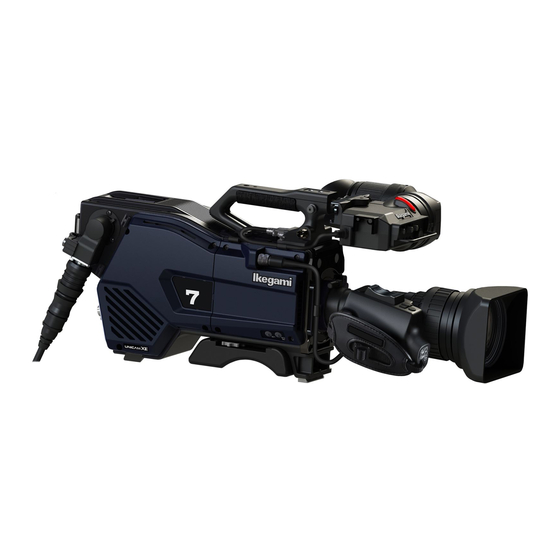
UHK-430
CCU-430
Portable Camera System
OPERATION MANUAL
CCU
OFF
EXT
4K/HD
Advertisement
Table of Contents


Need help?
Do you have a question about the CCU-430 and is the answer not in the manual?
Questions and answers