
Subscribe to Our Youtube Channel
Related Manuals for Ikegami UHL-43


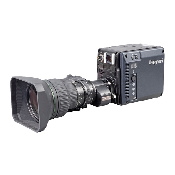
Summary of Contents for Ikegami UHL-43
- Page 1 Products conforming to RoHS directive UHL-43 Multi Purpose Camera OPERATION MANUAL...
- Page 2 Copyright © 2020 Ikegami Tsushinki Co., Ltd. Copyright © 2020 Ikegami Tsushinki Co., Ltd. We reserve the copyright on the software we create. We reserve the copyright on the software we create. Ikegami Tsushinki Co., Ltd. Ikegami Tsushinki Co., Ltd.
-
Page 3: Products Conforming To Rohs Directive
- If the customer mixed the lead-solder with the main body wiring or the circuit board, it becomes guarantee off the subject. Ikegami doesn't guarantee to do the repair work. Because the solder polluted with lead cannot be removed. 3. Parts Be sure to use parts conforming to RoHS directive. -
Page 4: Information To The User
: Multi Purpose Camera Model Name : UHL-43 Responsible Party : Contact Information Ikegami Electronics (U. S. A.) Inc 300 Route 17 South, Mahwah, NJ 07430, USA Tel : 201-368-9171 2. Declaration of conformity The CE mark means that the following products will meet and the Standards EN55032, EN-55035. -
Page 5: Safety Precautions
Indicates that mishandling may cause an electric shock. Indicates that mishandling may cause injury. The following symbol is used to indicate other precautions to prevent damage or hazard from occurring: Indicates prohibited action. UHL-43 2005 VER1 (E) - Page 6 Before connecting an accessories, make sure that the camera and equipment to be connected are powered off. Also, be sure to use dedicated cables. Excessive sound pressure from the headset may cause a hearing loss. UHL-43 2005 VER1 (E)
- Page 7 This product includes parts that wear out and have a limited life even in proper use or storage. Therefore, regular maintenance is recommended to extend the life and safe use of this product for a long time. Please contact Ikegami’s sales and service centers for the regular maintenance and repair of our products.
-
Page 8: How To Read The Operation Manual
HOW TO READ THE OPERATION MANUAL - - - This page explains general notes on reading the UHL-43 Operation Manual, and the symbols and notations used in the manual. Notes on the Manual - This manual is written for readers with a basic knowledge of handling broadcast cameras. - Page 9 Structure of Operation Manual This manual is intended to help you operate the UHL-43 safely and smoothly. This manual consists of seven chapters. We recommend you read them in sequence from Chapter 1 to Chapter 7 so that you can carry out all the work smoothly through the installation to the operation of the camera equipment.
-
Page 10: Table Of Contents
Executing automatic setup ... . 10 Adjusting the Lens ....11 viii UHL-43 2005 VER1 (E) -
Page 11: Chapter 1 Outline
(ICCP) is available as an option. Indicators - - - The UHL-43 provides tally and camera number (2 digit) on Digital Multi Purpose Camera, employing the same sensors the front side, and tally on the rear side, increasing visibility. -
Page 12: Chapter 2 Name And Function
Green light: Power is supplied. Red light : Warning indication. (6) VF front-back lock lever Caution This is on the optional handle. Check the warning contents and handle appropriately. For the explanation of warnings, refer to "Chapter 6 Troubleshooting." UHL-43 2005 VER1 (E) -
Page 13: Front Side
RS422_RX- Serial control signal (N) (VF -> Camera ) SIGNAL_GND Ground for Serial control signal (VF -> Camera) GND Insertion Side IKEGAMI_VF IKEGAMI VF connection control signal Camera side : HR10A-10R-12SC RS422_TX+ Serial control signal (P) (Camera -> VF) OUT... - Page 14 To connect a microphone or to input a line level audio signal. Plug receptacle HA16PRM-3S (05) Pin No. Name Shield ① ② Cold ③ Refer to "Chapter 5 Camera Setting and Adjustment" for the power to the microphone and the settings such as input level adjustment. UHL-43 2005 VER1 (E)
-
Page 15: Rear Side
BBS) is input to synchronize the camera. Ⓓ camera Synchronization signal (Tri-level sync) can be output by setting MU_REAR+12V DC+12V power supply (max. 2.0A) in the MENU. Ⓔ DGND Ground for DC+12V power supply Ⓕ RESERVE Ⓖ RESERVE Ⓗ UHL-43 2005 VER1 (E) -
Page 16: Bottom Side
To mount the camera to the tripod. It supports 3/8-16UNC screws (7 mm or shorter in length). (2) Camera mounting screw (1/4-20UNC) To mount the camera to the tripod. It supports 1/4-20UNC screws (6 mm or shorter in length). UHL-43 2005 VER1 (E) -
Page 17: Chapter 3 Installation And Connection
Avoid carrying the camera by holding the lens housing screw size at the tripod side. only. Applying excessive force to the lens mount can cause - Camera mounting screw (3/8-16UNC) damage. - Camera mounting screw (1/4-20UNC) UHL-43 2005 VER1 (E) -
Page 18: Power Supply Connection
When switching between the input and output of the GL IN/ SYNC OUT connector and for phase adjustment of the output POWER Switch video signal and the reference synchronous signal, refer to DC IN Connector DC POWER Cable "Chapter 5 Camera setting and adjustment". UHL-43 2005 VER1 (E) - Page 19 The GL IN/SYNC OUT connector can be switched to an output connector for the synchronization signal. The phase between the output video signals and the output synchronization signals are the same. Note The output synchronization signal is TRI-LEVEL SYNC only. UHL-43 2005 VER1 (E)
-
Page 20: Chapter 4 Operation
The auto setup chart is required. (2) LEVEL auto setup Set the video processing levels. This process can be executed daily before using the camera. The auto setup chart is required. UHL-43 2005 VER1 (E) -
Page 21: Adjusting The Lens
Adjust the Flange Back focus. under this condition. Note - Lock at the MONITOR output screen and shoot a subject white). A subject with detailed patterns is easier to adjust the focus. UHL-43 2005 VER1 (E) - Page 22 4 Operation R S ring ocu ring d u t ring oom roc er R S mode - - - An example of the flange back adjustment chart Siemens star chart UHL-43 2005 VER1 (E)
-
Page 23: Chapter 5 Camera Setting And Adjustment
Flash display Cursor mark By turning the MENU RE, move the cursor mark on the Main menu screen to the item to be set. The item which the cursor is moved to starts blinking. UHL-43 2005 VER1 (E) - Page 24 MENU RE. of the setting, move the cursor mark to the return mark and press the MENU RE. Note If the MENU RE is not pressed after changing setting, the change may become invalid. UHL-43 2005 VER1 (E)
- Page 25 For example, when A is registered to No. 1 and B is registered to No. 2, if No. 1 is moved to No. 2 by using "MOVE," No. 1 becomes vacant, and No. 2 becomes A. UHL-43 2005 VER1 (E)
-
Page 26: Menu Structures And Contents
It sets the tally display and conditions to display the zebra pattern. ⑩ FAN CONTROL It sets the operating conditions of the air cooling fans ⑪ FILE OPERATION It saves and recalls data using a USB memory. UHL-43 2005 VER1 (E) - Page 27 ON, OFF Sets the ON/OFF of the colorbar title display. ― DISPLAY Edits the characters of the colorbar title display. ― TITLE EDIT Sets the position of the colorbar title display. ― POSITION ON, OFF ― BLINK UHL-43 2005 VER1 (E)
- Page 28 Set ON/OFF and position of PINP. ― PICTURE-IN-PICTURE [VF] Sets ON/OFF of the function that increases the color strength of the VF OFF, ON ― CHROMA UP [VF] video. << FOCUS ASSIST continues to the next page >> UHL-43 2005 VER1 (E)
- Page 29 The contents set in the ASSIST DATA SETTING menu are stored as ASSIST N0.1 to N0.4 DATA. Select the numbers you wish to store from No. 1 to No. 4 and write over ― STORE DATA the present data to store them. UHL-43 2005 VER1 (E)
- Page 30 ― UHDTV 4K COLOR BARS ARIB HLG SMPTE, ARIB, 100/100, SMPTE ― HDTV COLOR BARS 75/75, ARIB HLG ― ARIB BARS TYPE Selects the HDTV Output COLOR BAR. ― SMPTE BARS TYPE Sets the ON/OFF of CAL. UHL-43 2005 VER1 (E)
- Page 31 F.PORTABLE : Fujinon portble lens F.STUDIO : Fujinon studio lens F.FIELD : Fujinon field lens : Zoom tracking DTL is OFF. ENABLE ENABLE, DISABLE Sets the ENABLE/DISABLE to the serial interface of the lens. SERIAL I/F ( E ) UHL-43 2005 VER1 (E)
- Page 32 Sets the function to the FUNCTION switch F3. VF F3 SW [VF] TALLY, USRMRK, VSC, WFM, ZMPEAK, P-IN- P(VF), GAMMA1.4, FOCUS ASSIST, P-IN- TALLY Sets the function to the FUNCTION switch F4. VF F4 SW [VF] P(RET) UHL-43 2005 VER1 (E)
- Page 33 DISABLE : Manually adjusts the angle of view of the chart when FULL AUTO SETUP is performed. ABB, AWB Creates the convergence value (EXT REF FILE) of AWB and ABB. ― REFERENCE SET << VIDEO ADJUSTMENT continues to the next page >> UHL-43 2005 VER1 (E)
- Page 34 Sets the NR (noise reducer). ― NR MODE STD, HI, HQ, LOW Setting of FIR-FILTER when the 4K image is converted to HD (1080i & 1080p) ― DOWN CONV FILTER << VIDEO ADJUSTMENT continues to the next page >> UHL-43 2005 VER1 (E)
- Page 35 >CUSTOM1to5, ALL ― USB MEMORY Saves the custom gamma data to the USB memory. ― SAVE Loads the custom gamma data from the USB memory. ― LOAD << VIDEO ADJUSTMENT continues to the next page >> UHL-43 2005 VER1 (E)
- Page 36 PUSH SET ---> CLR : Clears the preset data. ― DATA SAVE CANCEL : Exit "DATA CLEAR" without clearing the settings. BT.709 BT.709, BT.2020 Sets the transfer matrix. ― TRANSFER MATRIX << VIDEO ADJUSTMENT continues to the next page >> UHL-43 2005 VER1 (E)
- Page 37 ― CORR. LEVEL B Sets whether a character display indicator is shown on the VF or not ON, OFF when the aberration correction value is not properly received from the ― OAC GUIDE MARK serial lens. UHL-43 2005 VER1 (E)
- Page 38 Sets the magnification (×1/2/4/8) of VSC. ― [VF] ― SCALE [VF] RIGHT RIGHT, LEFT , CENTER Sets the display position (right/left/center) of vector scope. ― POSITION [VF] WHITE WHITE, GREEN Sets the display color (white/green) of VSC. ― COLOR [VF] UHL-43 2005 VER1 (E)
- Page 39 Sets the FAN operation of VF to AUTO/Force OFF/Force ON. SSLOW : The fan speed is very slow. CAMERA SLOW : The fan speed is slow. (information display) : Normal fan speed. FAST : The fan speed is fast. : Fan malfunction UHL-43 2005 VER1 (E)
- Page 40 READY, START, READY Execute the save. ― SAVE START CANCEL PROGRAM UPDATE ( E ) Updates all programs. (SOFT & P_MPU FPGA & P_PROC FPGA) ― FILE SELECT The package version is updated by this update. UHL-43 2005 VER1 (E)
- Page 41 ― RESET LOG 0 to 82 Sets the display number of ISCP LOG data. ― COMM LOG START START, STOP Starts the recording of LOG. ― LOG RUN << SYSTEM continues to the next page >> UHL-43 2005 VER1 (E)
- Page 42 ― MATRIX SELECT: ― OFF: ― BT.709: SMPTE ― SMPTE: ― EBU: The name can be customized in mode CUSTOM. 2020 ― BT.2020 USER1 ― USER1 USER2 ― USER2 << SYSTEM continues to the next page >> UHL-43 2005 VER1 (E)
- Page 43 (Information display) ― VF (Information display) Displays the serial number of the camera. SERIAL NUMBER (Information display) Displays the setting status of dip switches on the PCB. MODULE SW KEY DATA (Information display) ― 4K FORMAT UHL-43 2005 VER1 (E)
- Page 44 - The menu items marked with "(E)" at the end are [ENGINEER MENU] items. - The menu items marked with "[REMOTE]" at the end are optional REMOTE connector items. Those functions work only with optional REMOTE connector. UHL-43 2005 VER1 (E)
-
Page 45: Creation Of A Lens File
Chart on which Kent paper, etc. has been pasted Camera and the entire surface is a uniform white. Light SDI OUT connector Illumination meter Picture monitor Light (connect if required) Coax cable UHL-43 2005 VER1 (E) - Page 46 (AUTO SEL NAME display section) displays the model name which is automatically acquired from the lens. UHL-43 2005 VER1 (E)
- Page 47 5 Camera Setting and Adjustment Select "AUTO" from "FILE SET" and then select "START." Data acquisition starts. Memo Manual adjustments of GAIN, Flare and W.SHADING are available. - After adjusting with OCP and MCP, selecting "MANUAL" UHL-43 2005 VER1 (E)
-
Page 48: Using The Usb Memory
MENU RE OPERATION" sub menu when "PUSHSET → START" is displayed. Then select "CANCEL" and press the MENU RE. Select "USB MEMORY" and press the MENU Display the sub menu of "USB MEMORY". UHL-43 2005 VER1 (E) - Page 49 To enable writing over of data, change [NO] to [YES] and press the MENU RE. If [NO] has been selected, storage is cancelled and the system returns to step [3]. UHL-43 2005 VER1 (E)
- Page 50 [LOADING FILE] or while the access indicator is lighted, as data is being written to the USB memory. Removing it at this time could damage the USB memory data or the USB memory itself. Caution name normally. other than half-size letters of the alphabet. UHL-43 2005 VER1 (E)
-
Page 51: Allocation Of Functions To Function Switches
Depending on the connected device, it is possible the F switch is not provided. The blinking cursor moves to the set value field. Use the MENU RE to select the desired function. Press the MENU RE to confirm the selection. UHL-43 2005 VER1 (E) -
Page 52: Displays In The Viewfinder
Appears for 2 seconds when the Super V is turned on. Also it The step position is one of the following: -3dB, 0dB, +3dB, is displayed while CHAR switch is pressed. +6dB, +9dB, +12dB. Note Super V function works only on Interlace formats 1080i. UHL-43 2005 VER1 (E) - Page 53 See "5.2 Menu structures and contents" for how to set the side mask. Center Marker Safety Marker Title Area Frame Maker Reference Please refer to "5.2 Menu structures and contents" for the setting method of the markers. UHL-43 2005 VER1 (E)
-
Page 54: When The Status Indicator Lights Red
On the main menu (TOP MENU), turn the MENU status indication the power is turned Rotary Encoder (RE) to align the cursor to "FILE for a few OPERATION." Press the MENU RE to display seconds the sub menu. STATUS indicator red light UHL-43 2005 VER1 (E) - Page 55 - When "CANCEL" is selected with the MENU RE, the setting is cancelled, and "PRESET FILE LOAD" ends. - When "START" is selected, the lower section of the screen indicates "PUSH SET -> START." When "START" is set, the condition moves to Step 6. UHL-43 2005 VER1 (E)
-
Page 56: Fuse Replacement
Screws Blank panel Remove the following fuse and attach a new fuse. Caution Use the designated fuse or an equivalent one. Fuse to be used Model: 1044-0001 Housing color: Blue Rated current: 15A UHL-43 2005 VER1 (E) -
Page 57: Chapter 7 Specification
11 Ambient humidity No dew condensation W 145 x H 155 x D 169 12 Dimensions Approx. 2.6 kg 13 Weight Options excluded * 4K operation is an option 4-M4 Depth 5 22.4 105 ±1 ±0.5 UHL-43 2005 VER1 (E) - Page 58 USB 2.0, Type A, 4pin (x1) HR10A-10pin (x1) XLR-4pin DC IN XLR-type 3pin female (x1) ・ Input Level Step : -60, -50, -40, -30, -20, -10, 0, +4 dBu MIC input ・ Power Supply OFF/+48V * 4K operation is an option. UHL-43 2005 VER1 (E)
- Page 59 *1 Double speed is only works on PRODUCTION SERVER XT-3 from EVS. “EVS”and “XT-3”are trade mark of Belgian company EVS. Therefore, there are only limited equipment which can support receptions of HD-SDI (1.5G) Quad Link signals. UHL-43 2005 VER1 (E)
-
Page 60: Changing Information
CHANGING INFORMATION CHANGING INFORMATION CHANGING INFORMATION done by Ikegami. Read by comparing this information with the main part of the operation manual. UHK-430/CCU-430 1609 VER1 (E) - Page 61 Ikegami Tsushinki Co., Ltd. © May 2020 Ikegami Tsushinki Co., Ltd. - All rights reserved. Reproduction or duplication, without permission of Ikegami Tsushinki Co., Ltd. of editorial or pictorial content in whole or in part, in any manner, is prohibited.
- Page 62 Ikegami Tsushinki Co., Ltd. 5-6-16, Ikegami, Ohta-ku, Tokyo, 146-8567, Japan Phone : +81-(0)3-5700-4114 Fax : +81-(0)3-5748-2200 E-Mail : info_e@ikegami.co.jp URL : http://www.ikegami.co.jp/en/ Ikegami Electronics (U.S.A.),Inc. 300 Route 17 South, Mahwah, New Jersey 07430, U.S.A. Phone : +1-201-368-9171 Fax : +1-201-569-1626 E-Mail : engineering@ikegami.com, service@ikegami.com...
Need help?
Do you have a question about the UHL-43 and is the answer not in the manual?
Questions and answers