Christie Solaria CP2220 User Manual
Hide thumbs
Also See for Solaria CP2220:
- User manual (174 pages) ,
- Setup manual (70 pages) ,
- Installation and setup manual (19 pages)
Table of Contents
Advertisement
Quick Links
Download this manual
See also:
Setup Manual
Advertisement
Table of Contents

Subscribe to Our Youtube Channel
Related Manuals for Christie Solaria CP2220


Summary of Contents for Christie Solaria CP2220
- Page 1 CP2220 U S E R M A N U A L 020-100420-06...
- Page 3 CP2220 U S E R M A N U A L 020-100420-06...
- Page 4 Projector lamps (See Christie’s separate lamp program policy). c. Damage caused by use of a projector lamp beyond the recommended lamp life, or use of a lamp supplied by a supplier other than Christie. d. Problems caused by combination of the product with non-Christie equipment, such as distribution systems, cameras, video tape recorders, etc., or use of the product with any non-Christie interface device.
-
Page 5: Table Of Contents
Table of Contents 1: Introduction 1.1 Using this Manual........................1-1 1.1.1 Typographical Notations......................1-1 1.2 Safety Warnings and Guidelines ....................1-2 1.2.1 Labels and Marking ......................1-2 1.2.2 General Precautions ......................1-2 1.3 AC / Power Precautions.......................1-3 1.4 Lamp Precautions ........................1-3 1.4.1 Wear Protective Clothing.....................1-3 1.4.2 Cool the Lamp Completely....................1-4 1.5 Purchase Record and Service Contacts ..................1-4 1.6 Projector Overview........................1-5... - Page 6 Table of Contents 2.9.2 Adjusting Left/Right Boresight....................2-18 2.9.3 Adjust Top/Bottom Boresight ....................2-20 2.9.4 Add Anamorphic Lens ......................2-21 2.9.5 Wide Converter Lens ......................2-21 2.10 Fold Mirror and Convergence Adjustments ................2-21 2.10.1 DMD Convergence ......................2-21 2.10.2 Fold Mirror Adjustment ....................2-22 2.11 Calibrating the System.......................2-23 2.11.1 Color Calibration.......................2-23 2.11.2 Electronic Screen Masking ....................2-23 3: Operation...
- Page 7 Table of Contents Advanced Setup: Lens Setup Window .................3-36 Advanced Setup: Source File Setup Window ...............3-37 Advanced Setup: Screen File Setup Window ...............3-40 Advanced Setup: MCGD File Setup Window ..............3-43 Advanced Setup: TCGD File Setup Window ...............3-44 3.5.8 Administrator Setup Window ....................3-46 Administrator Setup: Preferred Channel Setup Window .............3-46 Administrator Setup: Preferred Test Pattern Setup Window ..........3-47 Administrator Setup: Preferences Window ................3-49...
- Page 8 Table of Contents Measured Color Gamut Data (MCGD) Instructions .............3-86 Channel Setup Instructions ....................3-87 3.8.4 System Test Pattern......................3-90 3.8.5 Verify 3D Cinema Content ....................3-93 3.8.6 3D Troubleshooting ......................3-93 3.9 Cinema Operation ........................3-94 3.9.1 Compatible Cinema Sources ....................3-94 3.9.2 Image Formats........................3-94 Projector Variables: Using an Anamorphic Lens ..............3-94 Projector Variables: Using a Wide Converter Lens ..............3-95 Theatre Variables: Masking ....................3-95...
- Page 9 Table of Contents 5: Troubleshooting 5.1 Power ............................5-1 5.1.1 Projector Does Not Power ON.....................5-1 5.2 Lamp ............................5-2 5.2.1 Lamp Does Not Ignite......................5-2 5.2.2 Lamp Suddenly Goes OFF ....................5-2 5.2.3 Flicker, Shadows Or Dimness .....................5-3 5.2.4 LampLOC™ Does Not Seem to Work................5-3 5.2.5 LiteLOC™...
- Page 10 Table of Contents 6.3.4 GPIO Port..........................6-5 6.3.5 Simple Contact Closure Interface (SCCI) Port ..............6-5 6.3.6 3D Port ..........................6-6 6.3.7 USB 1 Port ...........................6-6 6.3.8 USB 2 Port ...........................6-6 6.3.9 MALM (located on Auxiliary Input Panel) .................6-6 6.4 Touch Panel Controller ........................6-6 6.4.1 TPC-660E..........................6-6 6.4.2 TPC-650H ..........................6-7 6.5 Power Requirements ........................6-7...
-
Page 11: Using This Manual
Disclaimer: Every effort has been made to ensure the information in this document is accurate and reliable. However, due to constant research, the information in this document is subject to change without notice. Christie Digital Systems assumes no responsibility for omissions or inaccuracies. Updates to this document are published regularly, as required. -
Page 12: Safety Warnings And Guidelines
Section 1: Introduction Safety Warnings and Guidelines 1.2.1 Labels and Marking Observe and follow any warnings and instructions marked on the projector. DANGER Danger symbols indicate a hazardous situation which, if not avoided, will result in death or serious injury. This signal word is to be limited to the most extreme situations. Warning symbols indicate a hazardous situation which, if not avoided, could WARNING result in death or serious injury. -
Page 13: Ac / Power Precautions
Recommended protective clothing includes, but may not be limited to a polycarbonate face shield, protective gloves, and a quilted ballistic nylon jacket or a welder’s jacket. NOTE: Christie’s protective clothing recommendations are subject to change. Any local or federal specifica- tions take precedence over Christie recommendations. -
Page 14: Cool The Lamp Completely
4-7. Purchase Record and Service Contacts Whether the projector is under warranty or the warranty has expired, Christie’s highly trained and extensive factory and dealer service network is always available to quickly diagnose and correct projector malfunctions. Complete service manuals and updates are available for all projectors. Should a problem be encountered with any part of the projector, contact your dealer. -
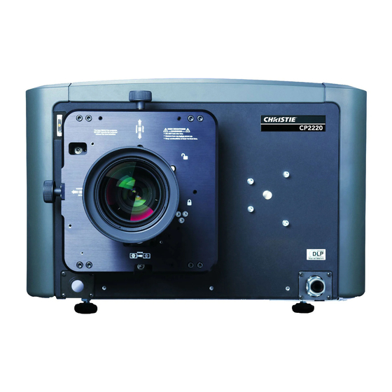
Page 15: Projector Overview
• Capable of supporting an internal image media block • One 10/100BaseT Ethernet port for connection to in-theatre Ethernet hub • Two RS-232 ports for communication: one for Christie-supported peripherals (except Cine-IPM 2K) and one for TI • One GPIO port for control of automation •... -
Page 16: How The Projector Works
Section 1: Introduction • Replaceable air filters (no tools required) • Capability to split power supply for use of Uninterruptible Power Supply (UPS) to power head electronics • Optional Rack Mount Stand • Choice of field-interchangeable zoom lenses and anamorphic lenses •... -
Page 17: Air Filter Cover And Air Filter
Section 1: Introduction Air Filter Cover and Air Filter Located directly behind the air filter cover is a field replaceable air filter. The air filter is responsible for filtering the intake air before it begins circulating in the front compartment to cool the main electronics. Replace the air filter whenever the lamp is replaced or sooner in dusty/dirty environments. -
Page 18: Projection Lens
PIB Faceplate Connections: • Ethernet: Use the 10Base-T/100Base-TX Ethernet port for network connection to the projector. • GPIO: Connect external I/O devices, such as the Christie ACT, for remote control of a limited number of projector functions. Refer to Appendix D: GPIO Port for GPIO pinouts. -
Page 19: Touch Panel Controller (Tpc)
Section 1: Introduction • Reset: This button is slightly recessed into the faceplate to prevent accidental activation. It’s main purpose is to reset the electronics of the projector. After re-booting, the projector will return to its previous power mode (Standby or Full Power), however the lamp will not strike automatically and requires manual striking. •... -
Page 21: 2: Installation And Setup
2 Installation and Setup This section explains how to install, connect and optimize the projector for delivery of superior image quality. NOTE: Illustrations are graphical representations only and are provided to enhance the understanding of the written material. Site Requirements The following site requirements are required for safe installation and operation of the CP2220: Physical Operating Environment •... -
Page 22: General Installation Safety And Warning Guidelines
Section 2: Installation and Setup General Installation Safety and Warning Guidelines WARNING • QUALIFIED TECHNICIAN REQUIRED for all installations. This product must be installed in a restricted access location. • Never operate the projector without all of it’s covers in place. •... -
Page 23: Installation Instructions
Section 2: Installation and Setup Installation Instructions STEP 1 - Position the Projector 1. An optional rack stand (P/N 108-282101-02) and hold down clamp (P/N 116-100101-01) are available for use with the projector. If you intend to use the rack stand as part of your installation, refer to the instructions provided with the rack stand before continuing with the remaining installation steps. - Page 24 Section 2: Installation and Setup NOTES: 1) For best optical performance, avoid tilting the projector excessively. Use vertical offset of the lens instead. 2) The front-to-back tilt of the projector must not exceed 15°. This limit ensures safe lamp operation and proper position of the liquid cooling reservoir in the projector.
- Page 25 Section 2: Installation and Setup STEP 5 - Connect External Exhaust Ducting The projector emits a constant stream of warm exhaust air, which must Exhaust Duct to be vented to the outside of the building. Connect the site’s pre- Outside installed, outside-venting ductwork via the 8”...
- Page 26 Section 2: Installation and Setup STEP 6 - Install Lens The lens seals the projector preventing contaminants from entering the area of the main front electronics. CAUTION! Never operate a projector without a lens installed. For Primary Zoom Lens Installation: 1.
- Page 27 Section 2: Installation and Setup STEP 7 - Install First Lamp Qualified technician required! High-pressure lamp may explode if improperly DANGER handled. Always wear approved protective safety gear whenever lamp door is open or while handling the lamp. 1. Open lamp door. Using the security key provided, open the lamp door and inspect the empty lamp cooling compartment.
- Page 28 Section 2: Installation and Setup STEP 8 - Connect Power CP2220 is designed as a permanently wired connection or pluggable type B connection. Connecting the projector to your AC supply can vary according to the country or state in which the projector is installed. For any installation, always follow the electrical code for your location.
- Page 29 Section 2: Installation and Setup 4. Connect the AC power source to the terminal block, beginning with the ground lead first. See Figure 2-11 for wiring details. Use an appropriately sized strain relief connector with the knockout plate provided to ensure adequate environmental sealing and to prevent the cables from wear and accidentally being torn out.
- Page 30 Section 2: Installation and Setup Installing a Pluggable Type B Connection Guidelines: There must be easy access to the current protection device or breaker in the building. Use 10AWG or 8AWG wiring: the distance between the wall circuit breaker and the projector must not exceed 20 metres using 10AWG cables or 30 metres using 8AWG cables.
- Page 31 Section 2: Installation and Setup Configuring the Projector for Uninterrupted Power Supply (Optional) Located in the power compartment of the projector is an IEC 320 outlet where a UPS can be connected. This allows the projection head electronics to remain operable during a power failure reducing the recovery period of the projector.
- Page 32 Section 2: Installation and Setup STEP 9 - Connect Sources and Initial Power Up Once the lamp is installed, the projector is essentially ready for operation. Although an image is not required at this time, it is recommended that external cinema servers and sources be connected. Before igniting the lamp for the first time, it is essential the following steps be completed to ensure successful communication.
-
Page 33: Connecting Sources
Section 2: Installation and Setup Connecting Sources Cinema servers, such as digital media storage devices or non-cinema sources such as PCs reside outside the projector and are connected to one of the ports on the Projector Intelligence Board (PIB) located on the left (operator’s) side of the projector. - Page 34 Section 2: Installation and Setup From DVI Source Connect to AC at site Figure 2-16 Connecting Non-Cinema Sources 2-14 CP2220 User Manual 020-100420-06 Rev. 1 (03-2011)
-
Page 35: Connecting For Communications
For applications or equipment utilizing serial communications, use the . When using Christie serial Christie-proprietary serial protocol to connect to the RS232 PIB port on the PIB protocol over Ethernet connect to port 5000. NOTICE: The RS232 PIB port located on the PIB faceplate utilizes Christie-proprietary protocol and is intended for Christie accessories or automation controllers only. -
Page 36: Maximizing Light Output
Section 2: Installation and Setup Maximizing Light Output To ensure optimal operation and peak screen brightness, activate LampLOC™ to adjust the lamp position whenever a new lamp is installed in the projector. Once LampLOC™ adjustment is complete, the lamp will be well-centered and distanced correctly from the remainder of the illumination system. -
Page 37: Basic Image Alignment
Section 2: Installation and Setup Basic Image Alignment NOTES: 1) Assumes projector is fully assembled and powered up in its final location. 2) Projector in standard non-motorized lens mount configuration. 3) For information on how to adjust the projector’s displayed image using the motorized lens mount refer to Appendix A: Intelligent Lens System. This procedure ensures that the image reflected from the DMDs is parallel to and well-centered with the lens and screen. -
Page 38: Adjust Offset
Section 2: Installation and Setup 2.9.1 Adjust Offset Project an image with the primary lens only. Always adjust offset before boresight. Important! Ensure the correct lens is selected in the Advanced Setup: Lens Setup window before calibration to ensure you will remain within the applicable boundary of the installed lens when adjusting. - Page 39 Section 2: Installation and Setup 4. Continue retracting the lens. a. If the right side of the image comes into focus before the lens is completely retracted, then the image focuses in front of the screen. See Figure 2-22. To correct this problem, adjust the Horizontal Boresight Bolt to direct or aim the lens mount towards the LEFT to balance out the left/right edges.
-
Page 40: Adjust Top/Bottom Boresight
Section 2: Installation and Setup 2.9.3 Adjust Top/Bottom Boresight 1. When the horizontal boresight is complete, focus the image at the top edge of the screen. 2. Loosen the Vertical Hold Screw. Focus 3. Extend the lens focus completely. Top Center 4. -
Page 41: Add Anamorphic Lens
Section 2: Installation and Setup 2.9.4 Add Anamorphic Lens 1. Install the Auxiliary Lens Mount according to instructions provided in the kit. Make sure to optimize your primary lens first for best optical alignment, offset and boresight. 2. Image geometry distortion: Loosen the holding clamp on the auxiliary lens mount. Adjust the rotation of the anamorphic lens so the image remains perfectly square with anamorphic in and out. -
Page 42: Fold Mirror Adjustment
Section 2: Installation and Setup 2.10.2 Fold Mirror Adjustment If a corner or edge of the image is missing (after prime lens offset is ruled out), this may indicate the fold mirror has become misaligned with the rest of the optical system, resulting in cropping of data. To correct this issue, use the two adjustment screws that are accessible through the base of the projector. -
Page 43: Calibrating The System
Section 2: Installation and Setup 2.11 Calibrating the System Use the TPC interface for calibrating the image color performance and defining electronic screen masking. This is required in your particular installation for the creation of Source, Screen, MCGD and TCGD files necessary for proper display of incoming material. -
Page 45: Powering Up/Powering Down The Projector
3 Operation This section describes the software controls used for basic projector operation once it is properly installed, aligned and configured by a qualified service technician. Software controls are performed on the Touch Panel Controller (TPC) which is a portable, touch-sensitive screen mounted to the rear of the projector. For more information on the TPC, see 3.2 Using the Touch Panel Controller (TPC), on page 3-2. -
Page 46: Powering Down The Projector
Section 3: Operation 3.1.2 Powering Down the Projector 1. On the TPC, click and hold the Lamp OFF button for 1/4 second. NOTES: 1) The projector is still in “power on” mode, which allows for a fast lamp on response, if needed. 2) If you are turning off the power (going to Stand-by mode), there is no need to click the Lamp OFF button first. -
Page 47: Main Panel
Section 3: Operation Main Panel The main panel gives you easy access to the frequently used functionality when interacting with the projector. This includes the ability to select from nine user selected channels, Power, Lamp, Douser, Aux Lens, Lens Adjust, and Test Pattern Control. NOTE: Status LED in the context of the TPC window refers to a circular indicator that mimics a physical Light Emitting Diode (LED). - Page 48 Section 3: Operation Control Description 2: Channels Buttons Nine of the most commonly used channels display on the Main panel for easy access. Select these channels in the Administrator Setup: Preferred Channel Setup window. To start a feature or presentation, click the corresponding display Channel button to activate the channel.
-
Page 49: Aux Lens
Section 3: Operation Control Description 10: Operational Status Shows the status of top-level functionality in LED-like format to mirror the face- plate LEDs. Functionality includes Projector Intelligence Board (PIB), TI Elec- tronics Integrated Cinema Processor Board(s) (ICP), Link Decryptor (LD), Internal Media Block (IMB), Standby Power, Main Power, Run, and Marriage. -
Page 50: Test Patterns
Section 3: Operation All settings on the ILS Adjust window are in real-time. ILS settings are saved in a file called ILS Flat, ILS Scope, or a user-defined file where each channel specifies the ILS file to use. For more information on channel settings, refer to Channel Setup: Config 1 Window, on page 3-22. -
Page 51: Navigating The User Interface
Section 3: Operation 3.3.1 Navigating the User Interface Every window in the user interface has the same title bar (top of the window) and status bar (bottom of the window). Title Bar The title bar shows the current status of the system where the color of the LED indicates the state of the projector. -
Page 52: On Screen Keyboard
Section 3: Operation On Screen Keyboard Some options require a user input. When present, click the Launch Dialog button ( ) to launch the On Screen Keyboard (Figure 3-5) or On Screen Keypad. The On Screen Keypad will launch when entries require numerical values only. - Page 53 Section 3: Operation Table 3.4 Accessible Windows Per User Level Menu Status Operator Advanced Administrator Service Marriage Main Status Diagnostics (except DLP (except DLP - Interrogator - SMPTE Errors Management) Management) - System Logs - Server Test - DLP Management Network Devices Channel Setup - Config 1...
-
Page 54: Tpc Windows
Section 3: Operation TPC Windows 3.5.1 Status Window The Status window allows you to view read-only status information organized in groups of items where each item displays in a row of the form: LED, name, and value. The LED can be one of three colors: green, yellow, or red. - Page 55 Section 3: Operation Table 3.5 Summary of Status: System Components Displays all the status items that are in alarm state. Cooling Cooling Pump Card Cage Fanpack (bottom right) Card Cage Fanpack (top right) Intake Fanpack (bottom right) Intake Fanpack (bottom left) Intake Fanpack (top right) Intake Fanpack (top left) LAD Fan...
- Page 56 Section 3: Operation EVB State LVPS AC OK LVPS DC OK Lamp Info Lamp ID Lamp Serial Number Lamp Power Lamp power in watts Lamp Current Lamp current in amps Lamp Voltage Lamp voltage in volts Luminance Luminance in Foot Lamberts or Candela Lamp Intensity Current light intensity reading Lamp Expired Status...
- Page 57 Section 3: Operation PIB FPGA Factory PIB Main Production PIB Main Factory PIB Bootloader PIB CPLD Router Bootloader Router Kernel Router Sysfs LD Security List LD Software LD Login List ICP Software ICP OS ICP Kernel ICP RAM Disk ICP Software Boot ICP Firmware Boot ICP Software Main ICP Firmware Main...
-
Page 58: Alarm Window
Section 3: Operation 3.5.2 Alarm Window When an alarm condition is encountered, a full-screen red alarm window appears with a description of the alarm condition, state, and time the alarm occurred. (Figure 3-7). The list will not include alarms that the user has previously acknowledged even if they are still active. -
Page 59: Projector Led Status Indicators
Section 3: Operation 3.5.3 Projector LED Status Indicators In addition to the status indicators on the TPC, there are 2 sets of color-coded LED status indicators affixed to the top, rear corner of the projector skins - one set per side. These LEDs are designed to be easily viewable from a distance and on a wide angle so that the status of multiple projectors in a multiplex can be determined with a quick glance. -
Page 60: Diagnostics Window
Section 3: Operation 3.5.4 Diagnostics Window Required permission level - Operator (except DLP Management), Administrator or Service. Diagnostics: Interrogator Window The Diagnostics: Interrogator window captures the current state of the system that can assist in the diagnostics of projector components. It retrieves all of system logs and current configuration information and compresses it into a single file. -
Page 61: Diagnostics: Smpte Errors Window
Section 3: Operation To Run Interrogator 1. Click an Interrogator mode and then click the Yes button to start the Interrogator process. A progress bar will display until Interrogator is finished. Once started, the Interrogator cannot be stopped. During this time, you cannot modify the projector settings. -
Page 62: Diagnostics: System Logs Window
Section 3: Operation Table 3.8 Diagnostics: SMPTE Errors Window Region Control Description SMPTE Error 292-A Total The total count of 292-A errors. Counts 292-A Recent The recent count of 292-A errors. 292-B Total The total count of 292-B errors. 292-B Recent The recent count of 292-B errors. -
Page 63: Diagnostics: Dlp Management Window
Section 3: Operation Control Description Retrieve Logs Click to display the log information. Download to USB Click to download the system log information that displays on-screen to a USB drive. Open the back flap of the TPC to gain access to the 2 USB ports. Diagnostics: DLP Management Window The DLP Management window has controls for interacting with the TI Integrated Cinema Processor (ICP) electronics such as allowing you to turn off communication with the DLP hardware, copying the ICP/LD... -
Page 64: Network Devices
The Network Devices menu is an optional menu that only displays when a Network Device has been defined in the Administrator Setup: Network Devices Setup window. Network devices such as Christie ACT and an Integrated Media Block can be accessed. Refer to the 7. -
Page 65: Channel Setup Windows
Section 3: Operation 3.5.6 Channel Setup Windows Required permission level - Advanced, Administrator, or Service. Channels are projector presets that control how the projector handles and displays different content/inputs on the projection screen. In general, the options available through the Channel Setup window enable users to tailor projector processing for any type of incoming source, including 3D material, and collect these settings into a unique channel that any user can select from the Main panel. -
Page 66: Channel Setup: Config 1 Window
Section 3: Operation Control Description 2: Edit Name Click the Launch Dialog button to edit the name of the currently selected channel. 3: Active The check mark indicates the selected channel in the Channel Name list is the active channel. Channel Clicking the Activate button activates the currently selected channel. - Page 67 Section 3: Operation Table 3.12 Channel Setup: Config 1 Window Control Description 1: Icon Displays the icon associated with that channel. The Icon button allows you to select a new image from a list of available options. 2: Input Identifies/sets the location/connection of the current source, such as cinema port 292-A, 292-B or a DVI graphics port.
-
Page 68: Channel Setup: Config 2 Window
Section 3: Operation Channel Setup: Config 2 Window The Channel Setup: Config 2 window provides color configuration options. Figure 3-16 Channel Setup: Config 2 Window Table 3.13 Channel Setup: Config 2 Window Control Description 1: Measured For a given channel/source, select the desired Measured Color Gamut Data (MCGD) file representing native “uncorrected”... -
Page 69: Channel Setup: 3D Control Window
Section 3: Operation Channel Setup: 3D Control Window This window provides numerous controls for adjusting and synchronizing incoming 3D signals (often dual L/R HD-SDI signals at the SMPTE 292 A and 292 B ports with each other and with external 3D equipment such as screens, emitters and glasses.) For more details on setting 3D configurations, see 3.8 Working with 3D, on page 3-83. - Page 70 Section 3: Operation Region Control Description 3D Input 6: L/R Display Defines frame order (L-R or R-L) required for 3D perspective. Correct setting ensures smooth motions and depends entirely on the original source mastering. This option Control Sequence only has meaning when the Frame Rate factor M is equal to 2. For this case, 2 input frames of data are required to constitute a complete frame of image data.
- Page 71 Section 3: Operation FRAME RATE N:M NOTES These N:M ratios define how many frames to display per number of frames that EXAMPLE form one complete image. For all 3D use, the denominator is 2, indicating that 2 4:2 = 4 frames displayed 2 frames per image frames (left and right) are combined into every complete display frame.
-
Page 72: Advanced Setup Window
Section 3: Operation 3.5.7 Advanced Setup Window Required permission level - Advanced, Admin, or Service. The Advanced Setup windows consist of 8 windows (9 if ILS is installed) that enable users to define numerous operating parameters such as working with lamp settings and adjusting the lens position. It also offers a broad range of options used primarily for defining how the projector responds to incoming sources in the given environment when setting up the source, screen, MCGD, and TCGD files. -
Page 73: Advanced Setup: Lamp Power / Liteloc™ Setup Window
Section 3: Operation Control Description 2: Save As Displays a dialog to enter a new configuration name and saves the current on-screen settings to this file. 3: Save Saves the current configuration with the on-screen settings. Important! If you wish to save your set- tings to a new screen file, make sure to edit the screen file name before you save, otherwise, you will overwrite the settings of the loaded screen file. - Page 74 * The maximum power of the lamp power supply is restricted to 3000W ± 100W. Christie provides a wide lamp power range to give flexibility in meeting different exhibition configurations. However, older lamps may not always strike at the lowest power settings. For more details, see Section 6 Specifications.
-
Page 75: Advanced Setup: Lamp History Window
Section 3: Operation Advanced Setup: Lamp History Window The Advanced Setup: Lamp History window displays a read-only list of the previous and current lamps used by the projector. Once a lamp has been added, it can not be removed. When adding a new lamp, a separate dialog displays with editing boxes to record the new lamp type, serial number and the number of hours already logged on the lamp, if any. -
Page 76: Add Lamp Window
Section 3: Operation Add Lamp Window Figure 3-22 Advanced Setup: Add Lamp Window Table 3.19 Advanced Setup: Add Lamp Window Control Description Type In the Type list, select the lamp type. In the Serial Number box, click the Launch Dialog button to enter the serial number of the Serial Number new lamp. -
Page 77: Advanced Setup: Lamploc™ Setup Window
Section 3: Operation Advanced Setup: LampLOC™ Setup Window LampLOC™ buttons activate motors that reposition the bulb in the projector for optimized light output. Click the Do Auto button (recommended) to perform LampLOC™ or the individual buttons. NOTES: 1) The lamp must be ON before beginning LampLOC™. -
Page 78: Advanced Setup: Ils File Setup Window
Section 3: Operation Region Control Description 3: Auto Do Auto Starts the auto LampLOC™ calibration procedure, which adjusts the lamp posi- tion until the highest light reading is obtained from the light sensor. Displays the LampLOC™ LampLOC™ progress bar and Cancel Auto button. Display Full Select to temporarily display a full screen white test pattern for the duration of the LampLOC™... - Page 79 Section 3: Operation Figure 3-24 ILS File Setup Window Table 3.21 ILS File Setup Window Control Description Adjust the focus by clicking the clockwise/counterclockwise arrow buttons. Adjust one short Focus click at a time, several longer clicks, or hold the button for an accelerated movement. If the focus limit is reached, further clicks will have no effect on the value.
-
Page 80: Advanced Setup: Lens Setup Window
Section 3: Operation Advanced Setup: Lens Setup Window The Advanced Setup: Lens Setup window allows you to setup the primary and auxiliary lenses. If installed you can also setup the Intelligent Lens System (ILS). Figure 3-25 Advanced Setup: Lens Setup Window Table 3.22 Advanced Setup: Lens Setup Window Region Control... -
Page 81: Advanced Setup: Source File Setup Window
Section 3: Operation Region Control Description 2: Intelligent ILS Installed Ensure the ILS Installed check box is selected when the ILS is installed. Lens System Enable Auto- When selected, the lens will automatically move to the position associated with (Optional) the channel and all adjustments made to the focus, zoom, and offsets will over- matic ILS write the saved ILS values. - Page 82 Section 3: Operation Figure 3-26 Advanced Setup: Source File Setup Window Table 3.23 Advanced Setup: Source File Setup Window Control Description 1: Resolution Record the X/Y resolution of your incoming signal, such as 2048 (X) and 858 (Y) or 1920 (X) and 1080 (Y).
- Page 83 Section 3: Operation RESOLUTION NOTES To capture (or process) all of the incoming data, enter the full resolution of the incoming source material or leave at “0” (default). Regardless of whether or not the original material has been “squeezed” for use with an anamorphic lens, enter the current incoming resolution.
-
Page 84: Advanced Setup: Screen File Setup Window
Section 3: Operation Advanced Setup: Screen File Setup Window The Advanced: Screen File Setup window defines the portion of the projector’s display panel you wish to use and any cropping that is needed to disguise possible keystoning or other geometric aberrations. Once saved, a screen file can be used with any incoming source as desired. - Page 85 Section 3: Operation Control Description Cropping Cropping hides unwanted data, i.e. if the image appears keystoned. See Cropping Notes below. To adjust the top, left cropping point, select the top left option button and then adjust the X/Y val- ues using one of the two options: •...
- Page 86 Section 3: Operation Before After 80,175 1120,175 x=80 x=1000 y=200 y=200 x=1000 y=951 80,951 1120,951 Theatre Screen Cropping Settings for top, left corner of screen Figure 3-30 Cropping Example When projecting onto a curved screen, a bowed image sometimes results. To correct these bowed edges so that the image appears properly in the display, select the left middle option button and then adjust the Curve value using either the sliders to increase the value or click the Launch Dialog button in the Curve box to launch the on-screen keyboard and type a new value.
-
Page 87: Advanced Setup: Mcgd File Setup Window
Section 3: Operation Advanced Setup: MCGD File Setup Window The MCGD File Setup window allows you to record measurements for currently projected “uncorrected” colors. Recording the projector’s uncorrected color performance is typically completed as a final step after installation as a calibration. By default, the projector will use this MCGD to calculate and implement precise processing modifications needed to achieve any target color gamut on-screen, essentially compensating for the type of port window, screen, lens, light output, ambient light and other current environmental factors influencing on-screen colors. -
Page 88: Advanced Setup: Tcgd File Setup Window
Section 3: Operation To Record MCGD Color Settings For this one-time procedure for 2D displays, measure the initial “native” (i.e., uncorrected) x/y color coordinates for each color (Red, Green, Blue, and White) at the screen using a color meter. These values represent the current viewable primary colors and collectively defines the raw color performance or reference point for the projector in the current environment. - Page 89 Section 3: Operation Table 3.26 Advanced Setup: TCGD File Setup Window Control Description 1: Use White Clip Select the Use White Clip check box when playing back content encoded with the DCI XYZ color space. This will help bring the chromaticity of white within range with the projector without sacrificing output brightness or contrast.
-
Page 90: Administrator Setup Window
Section 3: Operation WHITE TOLERANCE NOTES If desired, define new tolerance coordinates for the current TCGD to increase or decrease this tolerance area or to change its shape or location. Larger boxes relax the tolerance reducing the loss of light caused by precise matching. -
Page 91: Administrator Setup: Preferred Test Pattern Setup Window
Section 3: Operation Table 3.27 Administrator Setup: Preferred Channel Selection Window Control Description 1: All Channels An alphabetical list of all 64 channels to choose from. 2: Selected A list of the nine buttons that display on the Main panel of the TPC. Buttons in this region can be dragged on top of one another to switch button locations. - Page 92 Section 3: Operation Table 3.28 Administrator Setup: Preferred Test Pattern Setup Window Control Description 1: Unselected An alphabetical list of all available test patterns for display by the projector for you to choose from. If a pattern is dragged to the User Selected region, it will be removed from this list. Patterns A list of test patterns specifically selected by the user.
-
Page 93: Administrator Setup: Preferences Window
Section 3: Operation Administrator Setup: Preferences Window The Preferences window provides access to various system parameters. Figure 3-37 Administrator Setup: Preferences Window Table 3.29 Administrator Setup: Preferences Window Region Control Description 1: General Temperature Units Select whether to display the temperature displayed on the TPC win- dows in Celsius or Fahrenheit, for example, the values in the Status: Temperatures window. -
Page 94: Administrator Setup: Content Devices Configuration
Section 3: Operation Region Control Description Select the Alarm Triggers check boxes for the conditions you want to 3: Alarm Over Temperature, Fan trigger an alarm window. Interlocks, communication faults, DMD over- Triggers Failure, Lamp Rotation, temperature and lamp failure are all permanent triggers. It is strongly Lamp Expiry, LD Log recommended all triggers remain selected during normal operation. -
Page 95: Administrator Setup: Time Setup Window
Section 3: Operation Region Control Description 2: IMB Select this if an IMB has been installed. Installed Administrator Setup: Time Setup Window The Time Setup window allows you to change the time zone and adjust the system time by up to ±15 minutes per year. -
Page 96: Administrator Setup: Communications Configuration Window
Section 3: Operation Administrator Setup: Communications Configuration Window The Communications Configuration window configures the Ethernet settings, serial communication parameters, SNMP settings, and remote access settings. NOTE: Record any new settings on page 1-1 of this manual. Figure 3-40 Administrator Setup: Communications Configuration Window 3-52 CP2220 User Manual 020-100420-06 Rev. -
Page 97: Subnet Mask
In the Serial Access list, select the degree of permission to grant serial access. Ethernet In the Ethernet Access list, select the degree of permission to grant Ethernet access. Access NOTE: Contact Christie for the SNMP V3 user ID and password. CP2220 User Manual 3-53 020-100420-06 Rev. 1 (03-2011) -
Page 98: Administrator Setup: Network Devices Setup Window
To Add a Network Device 1. Select a check box to the left of the Christie ACT or Integrated Media Block devices to enable the device. If you want to add a different device, in the Device Name text box, enter the device name or click the Launch Dialog button to enter the device name using the on-screen keyboard. -
Page 99: Administrator Setup: Gpio Setup Window
Section 3: Operation Administrator Setup: GPIO Setup Window The GPIO Setup window allows for the configuration of both input and output GPIO functions. For GPI, the system can be configured to trigger a specific pin either on a rising or falling edge. When the configured trigger is received, the function associated with that pin will be executed. -
Page 100: Administrator Setup: Foot Lamberts Calibration Window
Section 3: Operation Administrator Setup: Foot Lamberts Calibration Window The Foot Lambert Calibration window begins a series of panels that guides you through the process to calibrate the internal light sensor to Foot Lamberts. The left column of the Foot Lamberts Calibration window shows which state you’re currently at in the calibration process. - Page 101 Section 3: Operation Steps to Perform Foot Lamberts Calibration 1. Before starting the Foot Lamberts Calibration measurement process, ensure the lamp is ON and you have your light meter ready (Figure 3-43). Click the Next button to proceed to the Test Pattern window. If either of these two conditions are not met, the Next button will be disabled (greyed out) and will not let you proceed with the calibration.
- Page 102 Section 3: Operation Figure 3-45 Record the Meter Reading at Maximum Light Output 3. In the Maximum window, the projector sets the lamp to the maximum light output. Measure the screen light output at the screen with a light meter and enter the value in the Meter Reading text region by clicking the up/down buttons or clicking the Launch Dialog button to launch the on-screen keyboard to enter this value.
-
Page 103: Administrator Setup: User Accounts Window
Section 3: Operation Administrator Setup: User Accounts Window The User Accounts window provides options for the management of users, passwords, and user access rights. Depending on your login level, you will be able to manage users having the same or fewer access rights as you. Figure 3-46 Administrator Setup: User Accounts Window Table 3.34 Administrator Setup: User Accounts Window Control... -
Page 104: To Add A New User
Section 3: Operation Figure 3-47 Add a New User Window To Add a New User 1. Click the Add button to launch a dialog to enter the username, password and permission level for a new user. 2. In the Username list, click the Launch Dialog button enter the username using the on-screen keyboard. The username requires 4 - 32 characters with no numbers or special characters. -
Page 105: Administrator Setup: Upgrade Window
Section 3: Operation Administrator Setup: Upgrade Window The Upgrade window begins a series of steps to walk you through the upgrade process. You must login with Administrator or Service permissions to use the upgrade feature. The left column of the Upgrade window shows which state you’re currently at in the upgrade process. - Page 106 Section 3: Operation Upgrade: File Selection Window Figure 3-48 Upgrade: File Selection Window Table 3.35 Upgrade: File Selection Window Control Description Available The Available Upgrade Files region shows all the available upgrades that are currently residing in the FTP directory of the projector. Upon selecting an upgrade package, the Remove and Next but- Upgrade Files tons become active.
- Page 107 Section 3: Operation Upgrade: Package Details Window Figure 3-49 Upgrade: Package Details Window Table 3.36 Upgrade: Package Details Window Control Description Grid View Displays the available components in the upgrade package. This grid also displays the currently installed version along with the new version found in the upgrade package. If the current version and new version do not match, the row will be bold to indicate what will be upgraded.
- Page 108 Section 3: Operation Upgrade: Installation Window Figure 3-50 Upgrade: Installation Window Table 3.37 Upgrade: Installation Window Control Description Grid View Displays the available components that are being upgraded, their versions, the current progress and current status. Current state can be one of the following: idle, transferring, programming, aborted, failed, and done.
-
Page 109: Service Setup
Section 3: Operation 3.5.9 Service Setup Required permission level - Service or Marriage. Service Setup: File Management Window The File Management window enables the management of system backup and restore of various system settings. NOTE: In order to restore files properly DO NOT rename files backed up from File Management. Configuration - setup information for lamp, lens, communication settings, etc. -
Page 110: To Restore Backup Files
Section 3: Operation To Restore Backup Files 1. Click the Browse button to launch a file browser. 2. Navigate and select a saved backup file. Once a file is selected, the file path and name will display in the File to restore text region. 3. - Page 111 Section 3: Operation Steps to Perform Marriage 1. Ensure the system is in full power mode to proceed, i.e. Power is ON. Click the Next button to proceed to the Marriage Checklist window. (Figure 3-53). Figure 3-53 Administrator Setup: Marriage Checklist Window 2.
- Page 112 Section 3: Operation PRESS Marriage Emergency Start Reset Figure 3-54 Press the Marriage Button on the PI Board After Clicking the Arm Marriage Button 3-68 CP2220 User Manual 020-100420-06 Rev. 1 (03-2011)
- Page 113 Section 3: Operation 4. Upon clicking the Marriage button, a confirmation window displays the time remaining for marriage to complete. See Figure 3-54. Engaging Marriage Count Down Window Figure 3-55 5. Upon clicking the Marriage button, a confirmation window displays the time remaining for marriage to complete.
-
Page 114: Service Setup: System Access Window
Section 3: Operation Service Setup: System Access Window The System Access window provides access to the Windows operating system of the TPC. Table 3.39 Service Setup: System Access Window Control Description Click the Task Manager button to launch the system’s task manager. Task Manager Computer Management Click the Computer Management button to launch the system’s computer management... -
Page 115: Service Setup: Imb Marriage Window
Section 3: Operation Service Setup: IMB Marriage Window IMB marriage is identical in functionality to LD marriage. For details, refer to Service Setup: LD Marriage Window, on page 3-66. Figure 3-56 Service Setup: IMB Marriage Window CP2220 User Manual 3-71 020-100420-06 Rev. -
Page 116: Administrator Setup: System Access Window
Section 3: Operation Administrator Setup: System Access Window The System Access window provides access to the Windows operating system of the TPC. Administrator Setup: System Access Figure 3-57 Window Administrator Setup: System Access Table 3.40 Window Control Description Task Manager Click the Task Manager button to launch the system’s task manager. -
Page 117: About Window
Section 3: Operation 3.5.10 About Window The About window is a read-only interface that lists important information about the projector such as its serial number, the current software version, DLP version, type of lens installed, type of lamp installed., LD version and ICP version. -
Page 118: Help Window
Section 3: Operation 3.5.11 Help Window The Help window provides on-line information for every window in the TPC. Navigating the help system is done using the table of contents in the left column of the window. (Figure 3-59). The table of contents is structured similarly to the menus available from the Menu button where content is organized in sections shown with a book icon next to it ( ). -
Page 119: Working With The Lamp
Section 3: Operation Working with the Lamp Simple software controls and adjustments can help to optimize lamp performance and ensure the brightest, most uniform image possible for the life of the lamp. These controls are located in Advanced Setup: Lamp Power / LiteLOC™... - Page 120 Section 3: Operation Figure 3-60 Enable LiteLOC™ When should I use LiteLOC™? Typically, most theatre installations would use LiteLOC™ for daily operation, since it need only be set once for each lamp install and ensures consistent worry-free brightness at the screen for as long as possible. If desired, reset LiteLOC™...
-
Page 121: Using The Lamp Change Wizard
Section 3: Operation the LiteLOC™ setting, the recovery will be immediate. When re-enabling LiteLOC™ from a brightness setting that differs by only 10% or less, the recovery will be gradual. Understanding Lamp Power Values (%) The Lamp Power % region accepts values from 50-110, which represents the power appropriate for the installed lamp. - Page 122 Section 3: Operation 5. From the Type drop-down menu select the type of lamp you are installing. 6. Click the button to access the On Screen Keypad and manually enter the serial number of the lamp (Figure 3-62). 7. From the Reason for Figure 3-62 Add Lamp Window Change drop-down menu chose from:...
-
Page 123: Adjusting Lamp Position (Lamploc™)
Section 3: Operation 11. Once the lamp change is complete click Finish from the screen shown in Figure 3-64. Figure 3-64 Lamp Change Completed 3.6.3 Adjusting Lamp Position (LampLOC™) To ensure optimal lamp performance and peak brightness at the screen for the life of the lamp, activate LampLOC™... -
Page 124: Automatically Adjusting The Lamp Position Using Lamploc
Section 3: Operation Automatically Adjusting the Lamp Position Using LampLOC™ For best results in all installations, perform a LampLOC™ adjustment. This activates a set of motors and sensors in the projector to precisely position the lamp for optimized performance and brightness, while utilizing filtering to eliminate signs of lamp flicker. -
Page 125: Calibrating Screen Brightness (Fl)
Section 3: Operation 3. Adjust forward/aft (Z) until the brightness reading in front of the lens is maximized. 4. Adjust left/right (X) and up/down (Y) until the brightness reading in front of the lens is maximized. 5. Repeat Steps 3-4 as necessary. 6. -
Page 126: Working With The Lenses
Section 3: Operation lamp replacement and must be performed by a qualified service technician only. For details on rotating a lamp, 4.4.7 Rotating the Lamp, on page 4-10. Follow these steps and rotate the lamp 180° after loosening the cathode and anode lamp connectors. You must acknowledge that the lamp rotation has taken place by clicking the Acknowledge Lamp Rotation button on the Advanced Setup: Lamp History window before beginning normal operation again. -
Page 127: Lens Mount Functions
Section 3: Operation 3.7.1 Lens Mount Functions Zoom With the projector in its permanent location, turn the lens zoom ring on the primary lens to enlarge or shrink the image in each direction as necessary. Focus For overall focus improvements, rotate the focus adjustment knob. Offsets Adjust the horizontal offset and/or vertical offset knobs as necessary to keep the image square on the screen. -
Page 128: Hardware Requirements For 3D Cinema Setups
Section 3: Operation 3.8.1 Hardware Requirements for 3D Cinema Setups To display 3D, the CP2220 requires a 3D capable SMPTE source and a few special hardware / software setups as described below: • CP2220 projector • Two HD-SDI cinema signals (left and right) connected to the projector’s SMPTE ports HD-SDI A and HD- SDI B. -
Page 129: Hardware Setup
Section 3: Operation 3.8.2 Hardware Setup Refer to the illustrations provided for the general hardware configuration supported. Use either an IR emitter to control gating in active glasses, a polarizing Z-screen (Pi-cell) with passive glasses or filter wheel with passive glasses. -
Page 130: Installation For 3D Servers With Ycxcz Interface
Section 3: Operation 3.8.3 Installation for 3D Servers with YCxCz Interface Procedure Overview 1. Install the 3D system components on the projector following the appropriate installation instructions. 2. Configure lamp brightness for 3D content by editing the Default 3D lamp file and select this file for all 3D channels. -
Page 131: Channel Setup Instructions
Section 3: Operation Channel Setup Instructions Channel Setup: Config 1 Settings for 3D Configurations Figure 3-68 Channel Setup: Config 1 Settings for 3D Flat 1998 x 1080 Table 3.43 Channel Setup: Config 1 Settings for all 3D Configurations Feature 3D Flat 1998x1080 3D Scope 2048x858 1: Channel Name 3D Flat 1998x1080... - Page 132 Section 3: Operation Channel Setup: Config 2 Settings for 3D Configurations Figure 3-69 Channel Setup: Config 2 Settings for 3D Flat 1998 x 1080 Table 3.44 Channel Setup: Config 2 Settings for all 3D Configurations Feature 3D Flat 3D Scope 1998x1080 2048x858 1: Channel Name...
- Page 133 Section 3: Operation Channel Setup: 3D Control Settings for 3D Configurations Figure 3-70 Channel Setup: 3D Control Settings for 3D Flat 1998 x 1080 Table 3.45 Channel Setup: 3D Control Settings for all 3D Configurations Feature 3D Flat 3D Scope 1998x1080 2048x858 1: Channel Name...
-
Page 134: System Test Pattern
Section 3: Operation Frame Rate N:M - Sets how many frames to display per number of frames that form one complete image. This defines triple flash, where each image is shown three times to ensure a smooth, jitter free presentation. Other settings will still show 3D, but without as crisp a presentation. - Page 135 Section 3: Operation 100% black field with 100% red (TL), 100% black field with 100% white (TL), white (TR), blue (BR), green (BL) boxes red (TR), green (BR), blue (BL) boxes Figure 3-71 RGB-12 bit -3D Dynamic Range Test Pattern FRAME 1 - 100% white field box in FRAME 2 - 100% white field box in 100% black field...
- Page 136 Section 3: Operation FRAME 1 - 100 % white field with FRAME 2 - 50% white field with last lines 25% white and 75% black last line 75% white and 25% black FRAME 3 - 25% white field with FRAME 4 - 12.5% white field with last line 25% white and 75% black last line 75% white and 25% black Figure 3-73 RGB-12bit-3D Half Descending Test Pattern...
-
Page 137: Verify 3D Cinema Content
Section 3: Operation 3.8.5 Verify 3D Cinema Content After the hardware and software setup are complete, verify the synchronization of the server content. Play the actual 3D content while looking through the 3D cinema glasses to ensure the left and right eye display the content as intended. -
Page 138: Cinema Operation
Section 3: Operation Cinema Operation This section explains how trained operators can use the projector for presenting cinema events such as first-run movies stored on a digital media storage device. Read through these pages before displaying cinema for the first time. A good understanding of all cinema functions and how to access them will help you to run an event smoothly and easily. -
Page 139: Projector Variables: Using A Wide Converter Lens
Section 3: Operation Projector Variables: Using a Wide Converter Lens The optional Wide Converter Lens (WCL) acts similar to a zoom lens. It magnifies a “flat” image format of 1.85:1 to a “scope” image of 2.39:1, while maintaining the full resolution of the source material. The WCL simply mounts in front of a standard prime lens and expands the image just like a zoom of 1.26X, expanding the image to effectively decrease the throw ratio. -
Page 140: Non-Cinema Operation
Section 3: Operation 3.10 Non-Cinema Operation To display alternative content originating from standard definition or high definition non-cinema sources such as a PC or other graphics devices, connect your non-cinema DVI source to the DVI-D A and DVI-D B ports on the faceplate. -
Page 141: Ac / Power Precautions
4 Maintenance Installers, service trained operators and all other users must maintain a safe operating environment at all times. Read through this section in its entirety and understand all warnings and precautions before attempting to operate the projector. AC / Power Precautions Installation of this projector requires that an electrician hard-wire (permanent-wire) a single-phase feed from the projector to the AC supply at the building site. -
Page 142: Wear Protective Clothing
Recommended protective clothing includes, but may not be limited to a polycarbonate face shield, protective gloves, and a quilted ballistic nylon jacket or a welder’s jacket. NOTE: Christie’s protective clothing recommendations are subject to change. Any local or federal specifica- tions take precedence over Christie recommendations. -
Page 143: Liquid Cooling Air Filter
Top up the coolant with the Christie approved coolant Jeffcool E105. Use the refill bottle (with the nozzle) provided in the Liquid Coolant Fill Service Kit (#003-001837-xx). -
Page 144: Maintenance And Cleaning
Section 4: Maintenance NOTE: If the exhaust duct becomes significantly blocked, or if a fan fails, the projector’s airflow sensor should trigger a shutdown before the projector becomes overheated or unsafe. Regardless, check the airflow periodically. Maintenance and Cleaning To help ensure optimized performance and reliability, regularly check electrical, optical and other components as described below. -
Page 145: Cleaning The Lens
Section 4: Maintenance 4.4.3 Cleaning the Lens CHECK: Periodically A small amount of dust or dirt on the lens has minimal effect on image quality. To avoid the risk of scratching the lens, clean only if absolutely necessary. Dust: 1. Brush most of the dust off the lens with a camel-hair brush and/or blow dust away with compressed air. 2. -
Page 146: Other Components
The LAD filter is located in the light engine compartment. It is secured to the light engine assembly handle. The LAD filter should be nearly white in color. If it appears a dark gray color (rare) it will require replacement by a qualified technician only. Contact Christie or your dealer. CP2220 User Manual... -
Page 147: Lamp Replacement
Never twist or bend the quartz lamp body. Use the correct wattage lamp supplied by Christie. 3) Ensure those within the vicinity of the projector are also wearing protective safety gear. 4) Never attempt to remove the lamp when it is hot. The lamp is under a great deal of pressure when hot and may explode, causing personal injury or death and/or property damage. - Page 148 Section 4: Maintenance d. Handling by the cathode end only, unscrew the lamp from the cathode connector. Carefully remove the lamp from the projector and immediately place it inside the protective cover or original packaging. Caution! 1) Handle the lamp by the cathode/anode end shafts only, never the glass. e.
- Page 149 Section 4: Maintenance Figure 4-2 Install New Lamp STEP 7: Re-install the Front Lamp Duct Critical! As you install the front lamp duct, lift the small light shield on the rear lamp duct cover so that it does not get jammed between the two pieces when they come together.
-
Page 150: Rotating The Lamp
Never twist or bend the quartz lamp body. Use the correct wattage lamp supplied by Christie. 3) Ensure those within the vicinity of the projector are also wearing protective safety gear. 4) Never attempt to remove the lamp when it is hot. The lamp is under a great deal of pressure when hot and may explode, causing personal injury or death and/or property damage. -
Page 151: Liquid Cooling Air Filter Replacement
Section 4: Maintenance Liquid Cooling Air Filter Replacement CHECK: Monthly The radiator air filter is located on left/front side of the projector behind a small air filter cover. 1. Release a single tab on the air filter cover and remove. 2. -
Page 153: Power
5 Troubleshooting If the projector does not appear to be operating properly, note the symptoms and use this section as a guide. If the problem can not be resolved, contact your dealer for assistance. NOTE: A qualified service technician is required when opening an enclosure to diagnose any “probable cause”. -
Page 154: Lamp
4-7. Alternatively, if you hear a brief “click”, but no light appears, the lamp likely needs replacement. If you do not hear anything, it may indicate a problem with the LPS (Christie-trained service required). 5.2.2 Lamp Suddenly Goes OFF 1. Check the lamp power in the Advanced Setup: Lamp Power/LiteLOC Setup window. Try increasing the lamp power. -
Page 155: Flicker, Shadows Or Dimness
Try to increase lamp power, if possible. Lamps which are near end of life may not operate reliably at lowest power range. 6. Fold mirror misalignment (Christie service required). 7. Integrator rod misalignment (Christie service required). -
Page 156: Tpc
Section 5: Troubleshooting 1. If the TPC fails to initialize, re-boot the projector. 2. A failed TPC usually indicates a system failure requiring service. 3. If the TPC display is blank, ensure the TPC is on by opening the flap at the back of the TPC and verify the grey button in the bottom left corner is ON. -
Page 157: Image Appears Vertically Stretched Or 'Squeezed' Into Center Of Screen
Section 5: Troubleshooting 5.5.3 Image Appears Vertically Stretched or ‘Squeezed’ into Center of Screen Source data converted from film and “pre-squeezed” for the CP2220 display format may require use of an anamorphic lens (or resizing) to regain full “scope” image width and proper proportions. Verify the Resolution and Aspect Ratio settings in the Advanced Setup: Source File Setup window as well as the Lens Factor in the Advanced Setup: Screen File Setup window. -
Page 158: Display Has Suddenly Frozen
Section 5: Troubleshooting 5.5.8 Display has Suddenly Frozen If the screen blacks out inexplicably, it is possible that excessive voltage noise on the AC or ground input has interrupted the projector's ability to lock on to a signal. Power down the projector and then power back up again. -
Page 159: Portions Of The Display Are Cut Off Or Warped To The Opposite Edge
Section 5: Troubleshooting 5.5.14 Portions of the Display are Cut OFF or Warped to the Opposite Edge Resizing may need adjustment. Adjust until entire image is visible and centered. For more information, refer to Advanced Setup: Screen File Setup Window, on page 3-40. -
Page 161: Display
6 Specifications Due to continuing research, specifications are subject to change without notice. Display 6.1.1 Panel Resolution and Refresh Rate Pixel format (H x V square pixels) 2048 x 1080 Processing path 23.97 - 120Hz ® 3D (24 fps per eye input, DLP Cinema Processing), Full Image (2048 x 1080) 144Hz (frame tripled) 6.1.2 Achievable Brightness... -
Page 162: Source Signal Compatibility
Section 6: Specifications Source Signal Compatibility 6.2.1 Cinema Inputs • Number of inputs • Standard supported SMPTE 292M bit-serial • Connector type Table 6.1 Standard Single-link SMPTE 292M Formats Source Original Vertical Scan Type Display Frame Source Reso- Rate (Hz) Standard Frequency lution... - Page 163 Section 6: Specifications 640 x 480 23.98 / 24 Progressive 23.98 / 24 640 x 480 Progressive 640 x 480 29.97 / 30 Progressive 29.97 / 30 640 x 480 Progressive 640 x 480 Progressive 640 x 480 59.94 / 60 Progressive 59.94 / 60 640 x 480...
-
Page 164: Non-Cinema Dvi Inputs (For Alternate Content)
Section 6: Specifications 6.2.2 Non-Cinema DVI Inputs (for Alternate Content) • Number of inputs • Standard supported VESA Digital Visual Interface (DVI-D) • Connector type 24-pin female DVI-D Table 6.2 Format for Generic Inputs to DVI-D Ports, Single-Link NOTE: All formats listed are 4:4:4 RGB. Source Pixel Bits / Vertical... -
Page 165: Control Signal Compatibility
Bit Rate 115,200 bps Flow Control Hardware (RTS/CTS) Data Format 1 start bit, 8 data bits, 1 stop bit, no parity Communication Protocol Christie Serial Protocol 6.3.3 RS232-ICP Interface TIA-232 Connector 9-pin subminiature D, female Bit Rate 38,400 (default), 57,600, 115,200 bps, not auto-detected... -
Page 166: Port
Section 6: Specifications Output 1 - Projector Health (high = health ok) Input Current 5mA nominal, 50mA maximum Input forward voltage drop 1.1V nom., 1.4V max. (@5mA) 6.3.6 3D Port Interface Proprietary 3D connector Connector 15-pin subminiature D, female Bit Rate 1200 bps Flow Control Software... -
Page 167: Tpc-650H
Section 6: Specifications 6.4.2 TPC-650H Type of Display Color VGA TFT LCD, backlit Display Size 144.8 mm (5.7 inches) diagonal Display Resolution (H x V pixels) 640 x 480 Maximum Dimensions (W x H x D) 195 mm x 148 mm x 58 mm ®... -
Page 168: Physical Specifications
Section 6: Specifications Average Life: CDXL-20 3500 hours CDXL-30 2500 hours CDXL-30SD 2000 hours at 2.5kW / 1100 hours at 3 kW Wait time between lamp strikes 2 minutes min. Warm-up time to full brightness 20 minutes max. NOTE: Hot re-strikes reduce lamp life. Other lamps with bulb diameters not exceeding 70mm may also be used, however the projector may not meet its specified light output rating. -
Page 169: Environmental
Section 6: Specifications Environmental • EU Directive (2002/95/EC) on the restriction of the uses of certain hazardous substances (RoHS) in electri- cal and electronic equipment and the applicable official amendment(s) • EU Directive (2002/96/EC) on waste and electrical and electronic equipment (WEEE) and the applicable official amendment(s) •... - Page 170 Section 6: Specifications • 5.5-8.0 DLPCine HB Zoom Lens (108-280101-01) High Contrast Prime Zoom Lenses • 1.25-1.45 DLPCine HC Zoom Lens (38-809079-01) • 1.45-1.8 DLPCine HC Zoom Lens (38-809061-01) • 1.8 - 2.4 DLPCine HC Zoom Lens (38-809052-01) • 2.2-3.0 DLPCine HC Zoom Lens (38-809053-01) •...
-
Page 171: A: Intelligent Lens System
Appendix A: Intelligent Lens System A.1 Intelligent Lens System The optional Intelligent Lens System (ILS) automates the process of adjusting the Focus, Horizontal (X) and Vertical (Y) Offset, and Zoom in real-time using a motorized lens mount. ILS settings are saved in a file called ILS Flat, ILS Scope, or a user-defined file(s) where each channel specifies the ILS file to use. - Page 172 Appendix A: Intelligent Lens System Enable Automatic ILS Selected When the Enable Automatic ILS check box is selected, the ILS adjusts each motor for the focus, offset, and zoom to automatically move the lens based on the settings in the selected ILS file. Changing channels will change the position of the lens, assuming the new channel uses a different ILS file.
-
Page 173: Lens Mount Functions
Appendix A: Intelligent Lens System A.1.1 Lens Mount Functions WARNING 1) If present, move the Motorized Auxiliary Lens Mount (MALM) to the OUT position before performing any lens calibrate or reset functions on the Motorized Primary Lens Mount to prevent collision between the projection lens and the MALM. -
Page 174: Reset The Ils
Appendix A: Intelligent Lens System Permanently Alter the Active ILS Settings 1. Ensure the check box is selected. Enable Automatic ILS 2. Adjust the focus, Horizontal (X) and Vertical (Y) offset or zoom by clicking the applicable button. Adjustments can take place one step at a time or via continuous movement by holding the button down. NOTE: This over-writes the ILS settings. -
Page 175: Offset And Boresight Alignment
Appendix A: Intelligent Lens System A.2 Offset and Boresight Alignment The following instructions explain how to adjust the offset and boresight alignment using the ILS. Projectors without the ILS should refer to 2.8 Basic Image Alignment, on page 2-17. To ensure proper offset for your site and consistently good focus in all areas of the screen, a primary lens must be installed and its lens mount precisely adjusted in relation to internal optics as described below. -
Page 176: Adjust Left/Right Boresight
Appendix A: Intelligent Lens System A.2.2 Adjust Left/Right Boresight Horizontal Locking The goal for left/right boresight alignment is to adjust the lens mount Screw Horizontal until both sides of the image focus on the screen simultaneously. Boresight Bolt Projectors are aligned properly at the factory, but due to mechanical tolerances in the alignment between the projector and the screen, the left and right sides of the image come into focus at different times. -
Page 177: Adjust Top/Bottom Boresight
Appendix A: Intelligent Lens System 4. Continue retracting the lens. a. If the right side of the image comes into focus before the lens is completely retracted, then the image focuses in front of the screen. See Figure A-5. To correct this prob- lem, adjust the Horizontal Boresight Bolt to direct or aim the lens mount towards the LEFT to balance out the left/right edges. - Page 178 Appendix A: Intelligent Lens System b. If the top edge of the image fails to come into focus Focus Left then the image focuses behind the screen.To correct Edge Center this problem, adjust the Vertical Boresight Bolt to direct or aim the lens mount DOWN towards the bot- tom of the screen.
- Page 179 Appendix B: Serial API Table B.1 Function Codes Auxiliary Motorized Lens (AML) Control the motorized auxiliary lens (anamorphic or converter lens). Reset all preference and configuration settings in the device to their default values. The value of 111 must be sent with each of the sub codes as well as the default. The number 111 helps prevent accidental use of this control.
- Page 180 Appendix B: Serial API Baud Rate (BDR) Set the baud rate for a serial communications port. SUBCODE DESCRIPTION OF USE PRTA Set the baud rate on port A. Rates can be 1200, 2400, 9600, 19200, 38400, 57600, or 115200. EXAMPLES: (BDR+PRTA6) Set baud rate on port A to 115200 bits per second (BDR+PRTA?) Get baud rate (BDR+PRTA!006 ”115200) Channel (CHA)
- Page 181 Appendix B: Serial API Defaults (DEF) This control will reset all preference and configuration settings in the device to their default values. The value of 111 must be sent with each of the sub codes as well as the default. The number 111 helps prevent accidental use of this control. Select data packing format for selected input.
- Page 182 Appendix B: Serial API Data Format (DTF) Select data packing format for selected input. Available data formats depends on current input port (as selected by SIN). SUBCODE DESCRIPTION OF USE Cxxx Replace xxx with the channel number. Valid range is 101 - 164. NONE Select data format for current channel EXAMPLES:...
- Page 183 Appendix B: Serial API Focus Lens Position Adjustment (FCS) Adjust lens to specific focus position with a specified direction. NOTE: This command can only be used to update the current ILS file. Changing the focus for the current channel will change the focus for any channel using the same ILS file.
- Page 184 Appendix B: Serial API Lamp History (HIS) Retrieve the history of installed lamp entries, including the current lamp. There is an individual entry for each lamp in the history. The format for each entry is: (HIS!AAA “BBBB/BB/BB” “C” “D” EEE FFF GGG HHH III JJJ KKK).
- Page 185 Appendix B: Serial API Intelligent Light System Config (ILS) Enable/disable the Intelligent Lens System for each channel. SUBCODE DESCRIPTION OF USE ACLB Enable/disable the Auto Lens Mount and Lens reset feature. Once ACLB is turned on, lens mount and lens system will be reset automatically when system is powered on.
- Page 186 Appendix B: Serial API Internal Media Block Installed/Device Type (IMB) Access Level: Advanced Min Power Level: Power Down Used to set or query whether an IMB is installed or not. Use the DEVT subcode to set the device type. SUBCODE DESCRIPTION OF USE DEVT Set device type from the list of devices.
- Page 187 Appendix B: Serial API This control is used to calibrate (correlate) the intensity feedback mechanism to footlamberts. Note the minimum/ maximum power are used to pick two points on the curve. These points will not stay consistent over the life of the lamp, but the conversion algorithm will extrapolate the conversion beyond the range of the two end points.
- Page 188 Appendix B: Serial API SUBCODE DESCRIPTION OF USE None Set to 1 to installed and 0 to not installed. EXAMPLES: (LDI 1) Set LD installed. Lamp Intensity Calibration (LEN) Define model and serial number for primary installed lens and auxiliary lens. SUBCODE DESCRIPTION OF USE AMOD...
- Page 189 Appendix B: Serial API EXAMPLES: (LHO 500 1) Move lens to position 500 along horizontal axis with positive approach (LHO 500 -1) Move lens to position 500 along horizontal axis with negative approach (LHO+C101 -500 1) Set lens horizontal position for channel 1 to -500 with positive approach (LHO ?) Return current motor position along horizontal axis and direction (-1 or 1) (LHO+CALB 1) Calibrate the horizontal axis (LHO+RSET 1) Reset the horizontal axis...
- Page 190 Appendix B: Serial API NONE (LMV <lho><lvo><zom><fcs><lhodir><lvodir><zomdir><fcsdir>) where <lhodir>, <lvodir>, <zomdir>, and <fcsdir> represent the horizontal, vertical, zoom, and focus position information. Valid values for direction are 1 and -1. EXAMPLES: (LMV 1000 1500 500 -500 -1 -1 1 1) Local Settings (LOC) et the time format and display options for temperature units.
- Page 191 Appendix B: Serial API FLSK Return total failed lamp strikes on the installed lamp FRSK Return total failed lamp restrikes on the installed lamp LPOF Return total lamp unexpected off times on the installed lamp NONE Return lamp usage for current lamp in hours. TLSK Return total lamp strikes on the installed lamp EXAMPLES:...
- Page 192 Appendix B: Serial API SUBCODE DESCRIPTION OF USE Cxxx Replace Cxxx with the channel number. Valid range is 101-164. NONE Set lamp mode for the current channel. EXAMPLES: (LPM 0) Set Constant Power mode for current channel (LPM “Constant Power”) Set Constant Power mode for active channel (LPB+C101 1) Set intensity mode for channel 1 (LPM?) Get Lamp mode for active channel Lamp Power (LPP)
- Page 193 Appendix B: Serial API MOVR Moves the motor a given number of steps based on the current location. Write-only for v1.3 or newer. EXAMPLES: (LVO 500 1) Move lens to position 500 along vertical axis with positive approach (LVO 500 -1) Move lens to position 500 along vertical axis with negative approach (LVO+C101 -500 1) Set lens vertical position for channel 1 to -500 with positive approach (LVO ?) Return current motor position along vertical axis and direction (LVO+CALB 1) Calibrate the vertical axis...
- Page 194 Appendix B: Serial API EXAMPLES: (NET+ETH0 "192.168.1.35") Set new IP address on the MGMT Ethernet controller (NET+GATE "192.168.0.1") Set the gateway (NET+SUB0 "255.255.255.0") Set the subnet mask on the MGMT Ethernet controller (NET+HOST "MyHostName") Set the host name (NET+ETH0 ?) Retrieve IP address from the MGMT Ethernet controller. (NET+ETH0! 192.168.1.35) (NET+MAC0 ?) Retrieve MAC address from MGMT controller.
- Page 195 Appendix B: Serial API Change the power state of the projector. Data can be: 3 - Power OFF - all electronics power OFF except Projector Control Module (PCM). It's also called Standby mode. 1 - Power ON - projector is powered ON with lamp ON. 0 - Full power mode - projector is ready for lamp ON.
- Page 196 Appendix B: Serial API EXAMPLES: (SCF+C108 “FLAT”) Use file “FLAT” on channel 108 (SCF+C108?) Get screen file name on channel 108 (SCF?L) List all available entries of screen control Shutter/Douser (SHU) Open/Close shutter/douser SUBCODE DESCRIPTION OF USE NONE Select douser position 0 - douser removed from optical path 1 - douser blocking optical path STEP The number of steps the douser should be moved when opening/closing (default 60, minimum 30, maxi- mum 200)
- Page 197 Appendix B: Serial API EXAMPLES: (SNM+TSIP “xxx.xxx.xxx.xxx”) Sets the Trap IP address to xxx.xxx.xxx.xxx (SNM+TSIP “0.0.0.0”) Setting the IP address to 0.0.0.0 will stop SNMP Agent from sending the traps. (SNM+LHLT 1) Setting this flag to 1 will disable any future lamp half life traps (SNM+LEXT 1) Setting this flag to 1 will disable any future lamp expire traps (SNM+ENVT ?) Get the flag to see if V2 is enabled (1) or disabled (0) (SNM+ENVT 1) Enable SNMP V2...
- Page 198 Appendix B: Serial API System Status (SST) etrieve the various system status groups. SUBCODE DESCRIPTION OF USE ALRM Returns a summary of any active alarms CONF Returns configuration data - model, sn, build date, etc COOL Returns cooling data - cooling fans, air flow, etc HLTH Returns system health INTE...
- Page 199 Appendix B: Serial API Projector Platform and Motherboard Related Information (SYS) Query only command that returns version information. SUBCODE DESCRIPTION OF USE BACB Return backplane version information. FACB Return faceplate version information. PIBB Return PIB version information. EXAMPLES: (SYS+BACB?) Returns backplane version information. Target Color Gamut (TCG) Set the Target Color Gamut file.
- Page 200 Appendix B: Serial API Output Reference Delay (phase) (TDP) Set output reference delay phase for 3D control. This is an additional control for output timing relative to input timing. The data range is -180 to 180. SUBCODE DESCRIPTION OF USE Cxxx Replace xxx with the channel number.
- Page 201 Appendix B: Serial API 3D Frame Rate Multiple (TFR) Setup frame rate multiple for 3D control SUBCODE DESCRIPTION OF USE Cxxx Replace xxx with the channel number. Valid range is 101 - 164. NONE Select 3D frame rate for the current channel. EXAMPLES: (TFR?L) List all entries on the frame rate multiple factor (TFR+C101 3) Set frame rate multiple to “4:2”...
- Page 202 Appendix B: Serial API EXAMPLES: (TMD+DSTA?) 0 or 1 (DST OFF or DST ON) (TMD+DSTA 0) Turn daylight savigns OFF (0) or ON (1) (TMD+ZONE 20) Set time zone to EST (TMD+TIME? ) Get local time (TMD+TIME! 17:50:45) (TMD+TOFF 120) Increase the time by two minutes. (“TMD+TOFF: Disabled Control”) Error message returned when power is OFF.
- Page 203 Appendix B: Serial API STRT Start motor moving in specified direction, where direction can be (-1, 1). Write-only for v1.3 or newer. STOP Stops the motor. Write-only for v1.3 or newer. MOVR Moves the motor a given number of steps based on the current location. Write-only for v1.3 or newer. EXAMPLES: (ZOM 500 1) Move lens to position 500 with positive approach (ZOM 500 -1) Move lens to position -500 with negative approach...
- Page 205 Appendix C: SCCI Port The SCCI port (Simple Contact Closure Port) is a DB-9 (male) connector located on the PIB Faceplate board and is used to control a limited set of projector functionality through contact closures. The following table lists the control functions available through the SCCI.
- Page 207 Appendix D: GPIO Port The GPIO port is a 37-pin D-sub connector (female) located on the PIB Board and provides 8 input and 7 output signals for interfacing a wide range of external devices to the projector. The pins that are configurable on this connector are done through the Administrator Setup: GPIO Setup window (Figure D-1).
- Page 208 Appendix D: GPIO Port If you are wiring your own GPIO cable for use with a server or 3D device such as an IR emitter or a polarizer, follow the circuit diagram shown in Figure D-2. = 5 mA Recommended Operating Point = 50 mA Max.
- Page 209 Appendix E: 3D Connector The 3D connector is a 15-pin D-sub connector (female) located on the PIB Board. The following table lists the control functions available through the 3D connector. SIGNAL NAME DIRECTION DESCRIPTION +12V Power to 3D device. Maximum 1A (total between both +12V pins).
- Page 212 Corporate of ces Worldwide of ces USA – Cypress United Kingdom Hungary/Eastern Europe Beijing ph: 714-236-8610 ph: +44 118 977 8000 ph: +36 (0) 1 47 48 100 ph: +86 10 6561 0240 Canada – Kitchener Germany Singapore Korea ph: 519-744-8005 ph: +49 2161 664540 ph: +65 6877 8737 ph: +82 2 702 1601...
Need help?
Do you have a question about the Solaria CP2220 and is the answer not in the manual?
Questions and answers
Light On request suppressed due to Interlock failure