Leica GPS1200 Series Technical Reference Manual
Hide thumbs
Also See for GPS1200 Series:
- Field manual (212 pages) ,
- Manual (186 pages) ,
- User manual (153 pages)
Table of Contents
Advertisement
Quick Links
Advertisement
Table of Contents

Related Manuals for Leica GPS1200 Series


Summary of Contents for Leica GPS1200 Series
- Page 1 Leica GPS1200 Technical Reference Manual Version 5.0 English...
- Page 2 The type and the serial number of your product are indicated on the type plate. Enter the type and serial number in your manual and always refer to this information when you need to contact your agency or Leica Geosystems authorized service workshop. Type: _________________________ Serial No.:...
- Page 3 Validity of this manual • This manual applies to all GPS1200 instruments. Differences between the various models are marked and described. • The RX1200 is available as RX1210 or with touch screen functionality as RX1210T, RX1250X, RX1250Xc, RX1250T or RX1250Tc. The name RX1210 is used throughout the manual and may also represent the touch screen models.
- Page 4 Overall comprehensive guide to the product and Manual program functions. Included are detailed descriptions of special software/hardware settings and software/hardware functions intended for technical specialists. Refer to the following resources for all GPS1200 documentation and software: • the SmartWorx DVD • http://www.leica-geosystems.com/downloads...
-
Page 5: Table Of Contents
Real-Time Rover, Pole and Minipack 1.13 Real-Time Rover, All-on-Pole - Option 1 1.14 Real-Time Rover, All-on-Pole - Option 2 1.15 Using the Minipack 1.16 Checking and Adjusting the Circular Level on the Tribrach Antenna Heights Overview Mechanical Reference Planes, MRP Table of Contents GPS1200... - Page 6 Pillar Setup 2.3.2 Tripod Setup 2.3.3 Pole Setup Measuring Slope Antenna Heights Using GPS1200 without RX1200 Using RX1250 Overview Switching between Leica software and Windows CE desktop Sleep Mode Configuring Interfaces 4.4.1 Overview 4.4.2 Configuring SmartAntenna Interface 4.4.3 Configuring Clip-On Interface...
- Page 7 Creating a New Line/Area 9.4.3 Editing a Line/Area 9.4.4 Working Example Data Log Point Sorting and Filters 9.6.1 Sorting and Filters for Points, Lines and Areas 9.6.2 Point, Line and Area Code Filter 9.6.3 Stakeout Filter Table of Contents GPS1200...
-
Page 8: Gps1200
Table of Contents GPS1200 Manage...\Codelists 10.1 Terminology 10.2 Overview 10.3 Accessing Codelist Management 10.4 Creating/Editing a Codelist 10.5 Managing Codes 10.5.1 Accessing MANAGE Codes 10.5.2 Creating a New Code 10.5.3 Editing a Code 10.6 Managing Code Groups Coding 11.1 Overview 11.2... - Page 9 Accessing Projection Management 13.7.2 Creating a New Projection 13.7.3 Editing a Projection 13.8 Geoid Models 13.8.1 Overview 13.8.2 Accessing Geoid Model Management 13.8.3 Creating a New Geoid Model from the CompactFlash Card / Internal Memory 13.9 CSCS Models Table of Contents GPS1200...
- Page 10 Table of Contents GPS1200 Manage...\Configuration Sets 14.1 Overview 14.2 Accessing Configuration Set Management 14.3 Creating a New Configuration Set 14.3.1 Initial Steps 14.3.2 Configuration Set for Static Operations 14.3.3 Configuration Set for Post-Processed Kinematic Operations 318 14.3.4 Configuration Set for Real-Time Reference Operations 14.3.5...
- Page 11 Working Example 19.7 Seismic Recording 19.8 Ring Buffer 19.8.1 Overview 19.8.2 Configuring and Using a Ring Buffer Config...\Instrument Settings... 20.1 Antenna & Antenna Heights 20.2 Satellite Settings 20.3 Time Zone 20.4 Instrument ID 20.5 Set NET Parameters Table of Contents GPS1200...
- Page 12 Table of Contents GPS1200 Config...\General Settings... 21.1 Wizard Mode 21.2 Hot Keys & User Menu 21.3 Units & Formats 21.4 Language 21.5 Display, Beeps, Text 21.6 Start Up & Power Down Config...\Interfaces... - General 22.1 Overview 22.2 Accessing Configuration Interfaces 22.3...
- Page 13 23.1.3 Modems 23.1.4 Radios 23.1.5 RS232 23.1.6 SMARTgate 23.1.7 Hidden Point Measurement Devices 23.1.8 GPRS / Internet Devices 23.2 Accessing CONFIGURE Devices / CONFIGURE GPRS Internet Devices 23.3 Creating a New Device 23.4 Editing a Device Table of Contents GPS1200...
-
Page 14: Gps1200
Table of Contents GPS1200 Config...\Interfaces... - Controlling Devices 24.1 Digital Cellular Phones 24.1.1 Overview 24.1.2 Configuring a GSM Connection 24.1.3 Configuring a CDMA Connection 24.2 Modems 24.3 Radios 24.4 RS232 24.5 SMARTgate Boxes 24.6 Hidden Point Measurement Devices 24.7 GPRS / Internet Devices 24.8... - Page 15 Calling and Closing the Calculator from an Input Field for Numeric Characters Tools...\File Viewer Tools...\Licence Keys STATUS 31.1 STATUS Functions 31.2 STATUS: Survey... 31.2.1 Satellite Status 31.2.2 Real-Time Status 31.2.3 Current Position 31.2.4 Logging Status 31.2.5 Occupation Information Status 31.3 STATUS: Battery & Memory Table of Contents GPS1200...
-
Page 16: Gps1200
Table of Contents GPS1200 31.4 STATUS: System Information 31.5 STATUS: Interfaces... 31.5.1 Real-Time Input 31.5.2 ASCII Input 31.5.3 Tilt 31.5.4 Meteo 31.5.5 SmartAntenna 31.5.6 Internet 31.5.7 Event Input 31.5.8 Remote Interfaces 31.6 Bluetooth MapView Interactive Display Feature 32.1 Overview 32.2 Accessing MapView 32.3... - Page 17 COGO 37.1 Overview 37.2 Accessing COGO 37.3 Configuring COGO 37.4 COGO Calculation - Inverse Method 37.4.1 Inverse Point - Point 37.4.2 Inverse Point - Line 37.4.3 Inverse Point - Arc 37.4.4 Inverse Point - Current Position Table of Contents GPS1200...
-
Page 18: Gps1200
Table of Contents GPS1200 37.5 COGO Calculation - Traverse Method 37.5.1 Overview 37.5.2 Traverse with Azimuth/Bearing 37.5.3 Traverse with Angle Right 37.6 COGO Calculation - Intersections Method 37.6.1 Intersection with Bearing - Bearing 37.6.2 Intersection with Bearing - Distance 37.6.3 Intersection with Distance - Distance 37.6.4... - Page 19 Accessing Determine Coordinate System - One Point Localisation 40.2 Determine Coordinate System - Onestep Transformation 40.3 Determine Coordinate System - Twostep Transformation 40.3.1 Twostep Transformation 40.3.2 Computing the Grid Scale Factor 40.3.3 Computing the Height Scale Factor Table of Contents GPS1200...
-
Page 20: Gps1200
Table of Contents GPS1200 40.4 Determine Coordinate System - Classic 3D Transformation 1002 40.5 Computing Required Azimuth 1006 Reference Line 1008 41.1 Overview 1008 41.2 Accessing Reference Line 1013 41.3 Configuring Reference Line 1016 41.4 Managing Reference Lines/Arcs 1024 41.4.1... - Page 21 Timed Occupations for All Types of Operations 1178 44.6 Initialisation for Real-Time Rover Operations 1181 44.6.1 Terminology 1181 44.6.2 Accessing Initialisation for Real-Time Rover Operations 1183 44.6.3 Initialise while Moving 1185 44.6.4 Initialise while Static 1186 44.6.5 Initialise on Known Point 1188 Table of Contents GPS1200...
-
Page 22: Gps1200
Table of Contents GPS1200 Survey - Auto Points 1190 45.1 Overview 1190 45.2 Configuring Auto Points 1192 45.3 Auto Points for Post-Processed Kinematic and Real-Time Rover Operations 1200 45.4 Offset Points of Auto Points 1205 45.4.1 Overview 1205 45.4.2 Configuring Offset Points 1208 45.4.3... - Page 23 Configuring Volume Calculations 1296 48.4 Calculating Volumes 1298 48.4.1 Survey Points 1298 48.4.2 Triangulate Surfaces 1302 48.4.3 Compute Volumes 1308 Wake-Up 1312 49.1 Overview 1312 49.2 Creating a New Wake-Up Session 1315 49.3 Editing a Wake-Up Session 1319 Table of Contents GPS1200...
-
Page 24: Gps1200
GSA - GNSS DOP and Active Satellites 1364 F.10 GSV - GNSS Satellites in View 1366 F.11 LLK - Leica Local Position and GDOP 1368 F.12 LLQ - Leica Local Position and Quality 1370 F.13 RMC - Recommended Minimum Specific GNSS Data 1372 F.14... - Page 25 Appendix G Event Input Notify Message Format 1378 Appendix H Seismic Record Format 1380 Appendix I PPS Output Notify Message Format 1382 Appendix J AT Commands 1384 Index 1386 Table of Contents GPS1200...
-
Page 26: Equipment Setup
Equipment Setup GPS1200 Equipment Setup Receiver Ports Description All receiver ports of GPS1200 are part of the receiver front panel. Ports on the receiver GX1210 GX1220 GX1230, GX1230 GG, GX1200 with PPS/Event option, GRX1200 Classic front panel and GRX1200 Lite... - Page 27 PPS/Event option GRX1200 GG Pro c) Battery compartment A j) Port PPS: PPS output, on GX1200 with with CompactFlash card compartment PPS/Event option RX1200 in/out or remote interface d) LED indicators k) Port RX: in/out. 8 pin LEMO Equipment Setup GPS1200...
- Page 28 Equipment Setup GPS1200 e) Port P3: Power out, or remote interface in/out or remote f) data in/out, . 8 pin l) Port P2: Power out, data in/out, interface in/out LEMO . 8 pin LEMO or remote g) Port PWR: Power in. 5 pin LEMO...
- Page 29 Port P1 or port P3 Radio without housing, using a cable Port P1, port P2 or port P3 Radio in a housing of System500, using a Port P1, port P2 or port P3 cable External power Port PWR Equipment Setup GPS1200...
-
Page 30: Post-Processed Static Reference On Pillar
Equipment Setup GPS1200 Post-Processed Static Reference on Pillar The equipment setup described below is to be used for static operations on fixed surveying pillars. Description The receiver and the RX1200 if used can be assembled to make one unit. One connection is needed to connect the GNSS antenna which is mounted on the pillar to the receiver. - Page 31 GNSS antenna f) Receiver GX1210/GX1220/ AX1201/AX1202 GG/AT504/AT504 GG GX1230/GX1230 GG b) Carrier g) Two batteries c) Tribrach h) 2.8 m antenna cable d) Pillar plate if required i) CompactFlash card e) RX1210 if required j) Transport container Equipment Setup GPS1200...
- Page 32 Equipment Setup GPS1200 Equipment setup step- Step Description by-step If a pillar plate is being used, locate the pillar plate on the pillar. Screw the tribrach to the pillar plate or the pillar. Level the tribrach. Place and lock the carrier in the tribrach.
- Page 33 If the receiver is left in the container during use in high temperatures, the lid should be left open. Refer to the GPS1200 User Manual for operating and storage temperatures. Use an external battery such as GEB171 to ensure operation for a full day.
-
Page 34: Post-Processed Static Reference On Tripod
Equipment Setup GPS1200 Post-Processed Static Reference on Tripod The equipment setup described below is to be used for static operations over markers. Description The receiver and the RX1200 if used can be assembled to make one unit. The receiver is either clipped to the tripod leg or is placed in the transport container. - Page 35 Equipment setup GPS12_013 a) GNSS antenna g) Receiver AX1201/AX1202 GG GX1210/GX1220/GX1230/GX1230 GG b) Carrier h) Two batteries c) Height hook i) CompactFlash card Equipment Setup GPS1200...
- Page 36 Equipment Setup GPS1200 d) Tribrach j) Tripod e) 2.8 m antenna cable k) Transport container f) RX1210 if required Equipment setup step- Step Description by-step Set up the tripod. Mount and level the tribrach on the tripod. Ensure that the tribrach is over the marker.
- Page 37 If the receiver is left in the container during use in high temperatures, the lid should be left open. Refer to the GPS1200 User Manual for operating and storage temperatures. Use an external battery such as GEB171 to ensure operation for a full day.
-
Page 38: Post-Processed Kinematic, Pole And Minipack
Equipment Setup GPS1200 Post-Processed Kinematic, Pole and Minipack The equipment setup described below is to be used for post-processed kinematic rover surveys with extended periods of use in the field. Description The receiver is placed in the minipack. Connections are made to the GNSS antenna and the RX1200. - Page 39 GNSS antenna AX1201/AX1202 GG h) 1.6 m antenna cable b) Upper half aluminium pole with screw i) Minipack c) 1.2 m antenna cable j) 1.8 m, RX to GX cable k) Receiver d) Grip for pole GX1210/GX1220/GX1230/GX1230 GG Equipment Setup GPS1200...
- Page 40 Equipment Setup GPS1200 e) RX1210 l) Two batteries f) Holder for RX1210 on pole m) CompactFlash card g) Lower half aluminium pole Equipment setup step- Step Description by-step Screw the two halves of the pole together. Slide the grip onto the pole.
- Page 41 Pass the 1.8 m, RX to GX cable through the opening in the bottom corner of the minipack flap and up through a cable brake. Refer to paragraph "Position of cables in the minipack". Plug it into port RX on the receiver. Press PROG on the RX1210 to switch the receiver on. Equipment Setup GPS1200...
- Page 42 Equipment Setup GPS1200 Position of cables in the minipack a) 1.6 m antenna cable GPS12_035 b) 1.8 m, RX to GX cable to the RX1210 Next step IF the receiver And the RX1200 is Refer to chapter has been pre-programmed...
- Page 43 An incor- rectly mounted GNSS antenna will have a direct effect on the results. Refer to "1.15 Using the Minipack" for advice on using the minipack. Equipment Setup GPS1200...
-
Page 44: Post-Processed Kinematic, All-On-Pole - Option 1
Equipment Setup GPS1200 Post-Processed Kinematic, All-on-Pole - Option 1 The equipment setup described below is to be used for post-processed kinematic rover surveys with short periods of use, especially where there are many obstacles such as fences. Description The RX1200 is fixed to the pole grip with a holder. With another holder, the receiver is fixed to the pole. - Page 45 Equipment setup GPS12_015 a) GNSS antenna g) Receiver AX1201/AX1202 GG GX1210/GX1220/GX1230/GX1230 GG b) 1.8 m antenna cable h) Holder for receiver on pole c) Upper half aluminium pole with screw i) RX1210 Equipment Setup GPS1200...
- Page 46 Equipment Setup GPS1200 d) Grip for pole j) 1.0 m RX to GX cable e) Holder for RX1210 on pole k) Two batteries f) Lower half aluminium pole l) CompactFlash card Equipment setup step- Step Description by-step Screw the two halves of the pole together.
- Page 47 When using the upper pole half with stub, ensure that the GNSS antenna and the screw-to- stub adapter slide down the full length of the stub before tightening the locking ring. An incor- rectly mounted GNSS antenna will have a direct effect on the results. Equipment Setup GPS1200...
-
Page 48: Post-Processed Kinematic, All-On-Pole - Option 2
Equipment Setup GPS1200 Post-Processed Kinematic, All-on-Pole - Option 2 The equipment setup described below is to be used for post-processed kinematic rover surveys with short periods of use, especially where there are many obstacles such as fences. Description The RX1200, with the receiver attached, is fixed to the pole grip with a holder. One connec- tion is needed to connect the GNSS antenna to the receiver. - Page 49 Equipment setup GPS12_021 a) GNSS antenna f) Receiver AX1201/AX1202 GG GX1210/GX1220/GX1230/GX1230 GG b) Upper half aluminium pole with screw g) 1.2 m antenna cable c) Grip for pole h) Lower half aluminium pole Equipment Setup GPS1200...
- Page 50 Equipment Setup GPS1200 d) Holder for receiver together with RX1210 on i) Two batteries pole e) RX1210 j) CompactFlash card Equipment set-up step- Step Description by-step Screw the two halves of the pole together. Slide the grip onto the pole.
-
Page 51: Real-Time Reference, Single Tripod
GNSS antenna is mounted directly using screw fitting. If using stub and adapter, proce- dures may vary slightly. • Standard radio mounted in radio housing is used throughout the instructions. Digital cellular phones may also be used but the setup may differ slightly. Equipment Setup GPS1200... - Page 52 Equipment Setup GPS1200 Equipment setup GPS12_016 a) Radio antenna i) RX1210 if required b) Radio antenna arm 15 cm long j) Receiver GX1210/GX1220/GX1230/GX1230 GG c) GNSS antenna AX1201/AX1202 GG k) Radio in housing...
- Page 53 Press the ON/OFF button on the receiver for at least 2 s or PROG on the RX1210 to switch the receiver on. Next step IF the receiver AND the RX1200 is Refer to chapter has been pre-programmed not being used has been pre-programmed being used requires programming being used Equipment Setup GPS1200...
- Page 54 If the receiver is left in the container during use in high temperatures, the lid should be left open. Refer to the GPS1200 User Manual for operating and storage temperatures. Use an external battery such as GEB171 to ensure operation for a full day.
-
Page 55: Real-Time Reference, Two Tripods
GNSS antenna is mounted directly using screw fitting. If using stub and adapter, proce- dures may vary slightly. • Standard radio mounted in radio housing is used throughout the instructions. Digital cellular phones may also be used but the setup may differ slightly. Equipment Setup GPS1200... - Page 56 Equipment Setup GPS1200 Equipment setup GPS12_017 a) GNSS antenna AX1201/AX1202 GG j) Radio antenna arm 3 cm long b) Carrier k) 2.8 m antenna cable c) Height hook l) Telescopic rod d) Tribrach m) Base for telescopic rod...
- Page 57 Press the ON/OFF button on the receiver for at least 2 s or PROG on the RX1210 to switch the receiver on. Next step IF the receiver AND the RX1200 is Refer to chapter has been pre-programmed not being used has been pre-programmed being used requires programming being used Equipment Setup GPS1200...
- Page 58 If the receiver is left in the container during use in high temperatures, the lid should be left open. Refer to the GPS1200 User Manual for operating and storage temperatures. Use an external battery such as GEB171 to ensure operation for a full day.
-
Page 59: Real-Time Reference Using Smartantenna, Rx1250 And Ght56
Standard radio mounted in radio housing is used throughout the instructions. Digital cellular phones may also be used but the setup may differ slightly. • For extended operating times it is possible to power the SmartAntenna and the RX1250 simultaneously via an Y-cable with external battery. Equipment Setup GPS1200... - Page 60 Equipment Setup GPS1200 Equipment setup RX12_28TR a) SmartAntenna i) Radio housing b) Battery for SmartAntenna j) Transport container c) Height hook k) RX1250 d) Carrier l) Radio antenna e) Tribrach m) Battery for RX1250...
- Page 61 Screw the 90° TNC connector onto the radio housing. The 90° TNC connector is delivered with the GHT56. Screw the radio antenna onto the 90° TNC connector. Make sure that the radio antenna is in an upright position. Place the battery into the battery compartment of the GHT56. Equipment Setup GPS1200...
- Page 62 Equipment Setup GPS1200 Step Description To hang the GHT56 on the tripod leg, use the hook GHT57 delivered with the GHT56. Remove the mounting arm if attached to the GHT56. The mounting arm is used to mount RX1250 on a pole.
-
Page 63: Smartrover - External Radio
GNSS antenna is mounted directly using screw fitting. If using stub and adapter, proce- dures may vary slightly. • Aluminium poles are used. They may be replaced with their carbon fibre equivalent without any change to these instructions. Equipment Setup GPS1200... - Page 64 Equipment Setup GPS1200 Equipment setup RX12_31 a) SmartAntenna g) Lower half aluminium pole b) Battery for SmartAntenna h) Radio antenna c) Upper half aluminium pole with screw or stub i) Battery for RX1250X d) Grip for pole j) CompactFlash card...
- Page 65 Make sure that the radio antenna is in an upright position. Place the battery into the battery compartment of the GHT56. Attach the GHT56 and tighten the screw. Press PROG on the RX1250X to switch on. RX1250X and SmartAntenna are connected via Bluetooth. Equipment Setup GPS1200...
- Page 66 Equipment Setup GPS1200 Next step Refer to chapter the SmartAntenna interface has to be configured 22.10 the RX1250X has been pre-programmed the RX1250X requires programming When using the upper pole half with stub, ensure that the GNSS antenna and the screw-to- stub adapter slide down the full length of the stub before tightening the locking ring.
-
Page 67: Smartrover - External Radio, Maximized Radio Coverage
GNSS antenna is mounted directly using screw fitting. If using stub and adapter, proce- dures may vary slightly. • Aluminium poles are used. They may be replaced with their carbon fibre equivalent without any change to these instructions. Equipment Setup GPS1200... - Page 68 Equipment Setup GPS1200 Equipment setup RX12_32...
- Page 69 Attach the GHT56 to the pole and tighten the screw. Connect the radio antenna to the radio housing using the 1.2 m antenna cable. Press PROG on the RX1250X to switch on. RX1250X and SmartAntenna are connected via Bluetooth. Equipment Setup GPS1200...
- Page 70 Equipment Setup GPS1200 Next step Refer to chapter the SmartAntenna interface has to be configured 22.10 the RX1250X has been pre-programmed the RX1250X requires programming When using the upper pole half with stub, ensure that the GNSS antenna and the screw-to- stub adapter slide down the full length of the stub before tightening the locking ring.
-
Page 71: Real-Time Rover, Pole And Minipack
Aluminium poles are used. They may be replaced with their carbon fibre equivalent without any change to these instructions. • Standard radio mounted in radio housing is used throughout the instructions. Digital cellular phones may also be used but the setup may differ slightly. Equipment Setup GPS1200... - Page 72 Equipment Setup GPS1200 Equipment setup GPS12_018 a) GNSS antenna AX1201/AX1202 GG j) 1.8 m, RX to GX cable b) Upper half aluminium pole with screw or k) Receiver GX1210/GX1220/ stub GX1230/GX1230 GG c) Grip for pole l) Two batteries...
- Page 73 Pass the cable through the opening in the top of the minipack and down under- neath the receiver. Connect the first 1.2 m antenna cable to the radio. Connect the 1.6 m antenna cable to port ANT on the receiver. Equipment Setup GPS1200...
- Page 74 Equipment Setup GPS1200 Step Description Pass the 1.6 m antenna cable through a cable brake and down through the opening in the bottom corner of the minipack flap. Refer to paragraph "Position of cables in the minipack". Draw the required amount of cable out of the minipack and tighten the cable brake.
- Page 75 1.8 m, RX to GX cable c) 1.2 m antenna cable to connect radio housing and radio antenna GPS12_036 Next step IF the receiver AND the RX1200 is Refer to chapter has been pre-programmed being used requires programming being used Equipment Setup GPS1200...
- Page 76 Equipment Setup GPS1200 When using the upper pole half with stub, ensure that the GNSS antenna and the screw-to- stub adapter slide down the full length of the stub before tightening the locking ring. An incor- rectly mounted GNSS antenna will have a direct effect on the results.
-
Page 77: Real-Time Rover, All-On-Pole - Option 1
Aluminium poles are used. They may be replaced with their carbon fibre equivalent without any change to these instructions. • Standard radio mounted in radio housing is used throughout the instructions. Digital cellular phones may also be used but the setup may differ slightly. Equipment Setup GPS1200... - Page 78 Equipment Setup GPS1200 Equipment setup GPS12_019 a) GNSS antenna AX1201/AX1202 GG h) Radio in housing b) Upper half aluminium pole with screw i) Receiver GX1210/GX1220/GX1230/GX1230 GG c) 1.8 m antenna cable j) Holder for receiver on pole d) Grip for pole...
- Page 79 When using the upper pole half with stub, ensure that the GNSS antenna and the screw-to- stub adapter slide down the full length of the stub before tightening the locking ring. An incor- rectly mounted GNSS antenna will have a direct effect on the results. Equipment Setup GPS1200...
-
Page 80: Real-Time Rover, All-On-Pole - Option 2
Equipment Setup GPS1200 1.14 Real-Time Rover, All-on-Pole - Option 2 The equipment setup described below is to be used for real-time rover with short periods of use, especially where there are many obstacles such as fences. Description The RX1200, with the receiver attached, is fixed to the pole grip with a holder. One connec- tion is needed to connect the GNSS antenna to the receiver. - Page 81 1.2 m antenna cable b) Upper half aluminium pole with screw h) Lower half aluminium pole c) Grip for pole i) Radio antenna d) Holder for RX1210 and receiver on pole j) Radio in housing e) RX1210 k) Two batteries Equipment Setup GPS1200...
- Page 82 Equipment Setup GPS1200 f) Receiver GX1210/GX1220/ l) CompactFlash card GX1230/GX1230 GG Equipment setup step- Step Description by-step Refer to "1.6 Post-Processed Kinematic, All-on-Pole - Option 2". Follow steps 1. to Attach the radio in its housing to port P1 or P3 the receiver.
-
Page 83: Using The Minipack
Real-time rover, pole and minipack. Antenna pole strap Ensures the antenna pole does not sway around and remains as upright as possible. Pass the strap around the pole and fasten using the clip as shown in the diagram. GPS12_137 Equipment Setup GPS1200... - Page 84 Equipment Setup GPS1200 Hip belt The hip belt • transfers most of the weight from the shoulders to the hips when properly adjusted. • contains velcro attachments through which cables can be passed. GPS12_138 Internal net pouch The internal net pouch is designed for •...
- Page 85 1. Open the minipack halfway. 1. Open the minipack completely. 2. Tuck the flap inside. 2. Tuck the flap inside. 3. Secure it with the velcro pad. 3. Secure it with the velcro pad. 4. Tuck the flap under the receiver. Equipment Setup GPS1200...
-
Page 86: Checking And Adjusting The Circular Level On The Tribrach
Equipment Setup GPS1200 1.16 Checking and Adjusting the Circular Level on the Tribrach Description The circular level is used to level the antenna over the observation point. An incorrectly adjusted circular level means that the GNSS antenna is not properly levelled over the point. - Page 87 Check that no screw is loose. Check the adjustment of the circular level using the precision bubble. Is more adjustment necessary? • If no, the adjustment procedure is finished. • If yes, repeat steps 6. to 11. Equipment Setup GPS1200...
- Page 88 Equipment Setup GPS1200 Diagram GPS12_61...
- Page 89 Equipment Setup GPS1200...
-
Page 90: Antenna Heights
Vertical or slope height GPS1200 accepts vertical and slope antenna heights measured to the Mechanical Refer- ence Plane. For the majority of GNSS antennas, including all Leica GNSS antennas, the vertical antenna height is measured. Measurements required This is an overview of required measurements depending on antennas, setup and accesso- ries. - Page 91 IF the antenna is AND the accesso- AND the setup is THEN the measure- ries are ments required are standard standard GPS1200 pillar • vertical height to GPS1200/System500 the MRP. Refer to "2.2 Mechan- ical Reference Planes, MRP". standard non Leica •...
- Page 92 Vertical phase centre For Leica antennas: Are handled automatically in the standard antenna records. variations For non Leica antennas: Can be stored in a newly created antenna record. Antenna records including azimuth and elevation dependent corrections need to be created using LGO.
-
Page 93: Mechanical Reference Planes, Mrp
• is where the phase centre variations refer to. • varies for different antennas. The MRP is shown for each GPS1200 antenna. AX1201/AX1202 GG a) The mechanical reference plane is the under- side of the threaded metal insert. GPS12_028... - Page 94 Antenna Heights GPS1200 AT504/AT504 GG 379.4 mm a) The mechanical reference plane is the under- side of the preamplifier housing. The AT504/AT504 GG is built to a JPL design spec- 34.5 mm GPS12_030 ified by the IGS for reference stations.
-
Page 95: Determining Antenna Heights
Determining Antenna Heights 2.3.1 Pillar Setup • One of the Leica standard antennas is used: AX1201, AX1202 GG, SmartAntenna, AT504, AT504 GG, AT501, AT502, AT503. • Leica standard accessories are used. Antenna Heights GPS1200... - Page 96 Antenna Heights GPS1200 Pillar setup a) Mechanical reference plane b) Vertical phase centre offset for L1 c) Vertical phase centre offset for L2 d) Vertical height reading An AX1201/AX1202 GG antenna is GPS12_031 shown. Vertical offset = 0 Vertical height reading The vertical height reading is the height difference between the pillar benchmark and the mechanical reference plane of the antenna.
- Page 97 MRP of the antenna sits on the carrier. Add the values determined in step 1. and 2., to get the vertical height reading. For Leica standard antennas plus accessories, the vertical offset is 0.00 m. Antenna Heights GPS1200...
- Page 98 Antenna Heights GPS1200 Carrier and adapter dimensions GPS12_037 GPS12_038 GRT144 carrier with GAD31 screw-to-stub GRT146 carrier. adapter. Next step • At the beginning of a survey, enter the vertical height reading into the receiver. • The vertical offset of 0.00 m is stored in the antenna setup record for a pillar setup and...
- Page 99 For carriers other than those shown in the diagram above, the dimensions must be deter- mined. Except for Leica standard antennas plus accessories, the vertical offset must be measured. This value must be entered in the antenna setup record. Antenna Heights...
-
Page 100: Tripod Setup
Antenna Heights GPS1200 2.3.2 Tripod Setup • One of the Leica standard antennas is used: AX1201, AX1202 GG, SmartAntenna, AT504, AT504 GG, AT501, AT502, AT503. • Leica standard accessories are used. - Page 101 An AX1201/AX1202 GG antenna is shown. GPS12_032 Vertical height reading The vertical height reading is the height difference between the ground mark and the bottom end of the height hook. It is determined using the height hook. Antenna Heights GPS1200...
- Page 102 For other height measurement devices than the height hook, the dimensions must be deter- mined and the vertical offset must be adapted. For other than Leica standard antennas, the vertical offset must be measured. It must be entered in the antenna setup record.
-
Page 103: Pole Setup
2.3.3 Pole Setup • One of the Leica standard antennas is used: AX1201, AX1202 GG, SmartAntenna, AT502, AT503. • Leica standard accessories are used. Pole setup a) Mechanical reference plane b) Vertical phase centre offset for L1 c) Vertical phase centre offset for L2... - Page 104 The vertical height reading for • the Leica standard pole consisting of an upper and a lower half is 2.00 m. • the Leica standard pole consisting of an upper and a lower half with an addi- tional 1.00 m pole section added is 3.00 m.
-
Page 105: Measuring Slope Antenna Heights
Vertical phase centre offset for L1 f) Vertical phase centre offset for L2 An AT504/AT504 GG antenna, Dorne Margolin T, as specified by the IGS is shown. The mechanical reference plane will differ GPS12_034 depending on the antenna type used. Antenna Heights GPS1200... - Page 106 Antenna Heights GPS1200 Determine the slope The slope height reading is the height difference between the ground marker and the outside height reading edge of the antenna. Next step • Determine the horizontal and vertical offset. • At the beginning of a survey, enter the slope height reading. The horizontal and vertical offsets must also be configured in MANAGE Antennas.
- Page 107 Antenna Heights GPS1200...
-
Page 108: Using Gps1200 Without Rx1200
Using GPS1200 without RX1200 GPS1200 Using GPS1200 without RX1200 For reference stations in post-processing, real-time and static applications, GPS1200 can be used without RX1200. Description The receiver is pre-programmed in the office using the RX1200. In the field, the receiver is used without the RX1200 attached. - Page 109 "LED Indicators". Check the stop time. Note down the stop time. LED Indicators Description Every GPS1200 receiver has three Light Emitting Diode indicators positioned below the ON/OFF button. They indicate the basic receiver status. Diagram Tracking LED Memory LED...
- Page 110 Using GPS1200 without RX1200 GPS1200 Description of the LED’s IF the LED THEN no satellites are tracked. green enough satellites are tracked to compute a posi- tion. flashing green the first satellite is tracked, a position is not yet available.
- Page 111 LGO for post-processing. A field record sheet is intended for writing down this necessary information such as point ID and antenna height. Example Field Record Date: Local start time: Local stop time: Receiver serial no.: Operator name: Point ID: Antenna height: Using GPS1200 without RX1200 GPS1200...
-
Page 112: Using Rx1250
Using RX1250 GPS1200 Using RX1250 Overview Description Some important characteristics of the RX1250 are explained in this chapter. -
Page 113: Switching Between Leica Software And Windows Ce Desktop
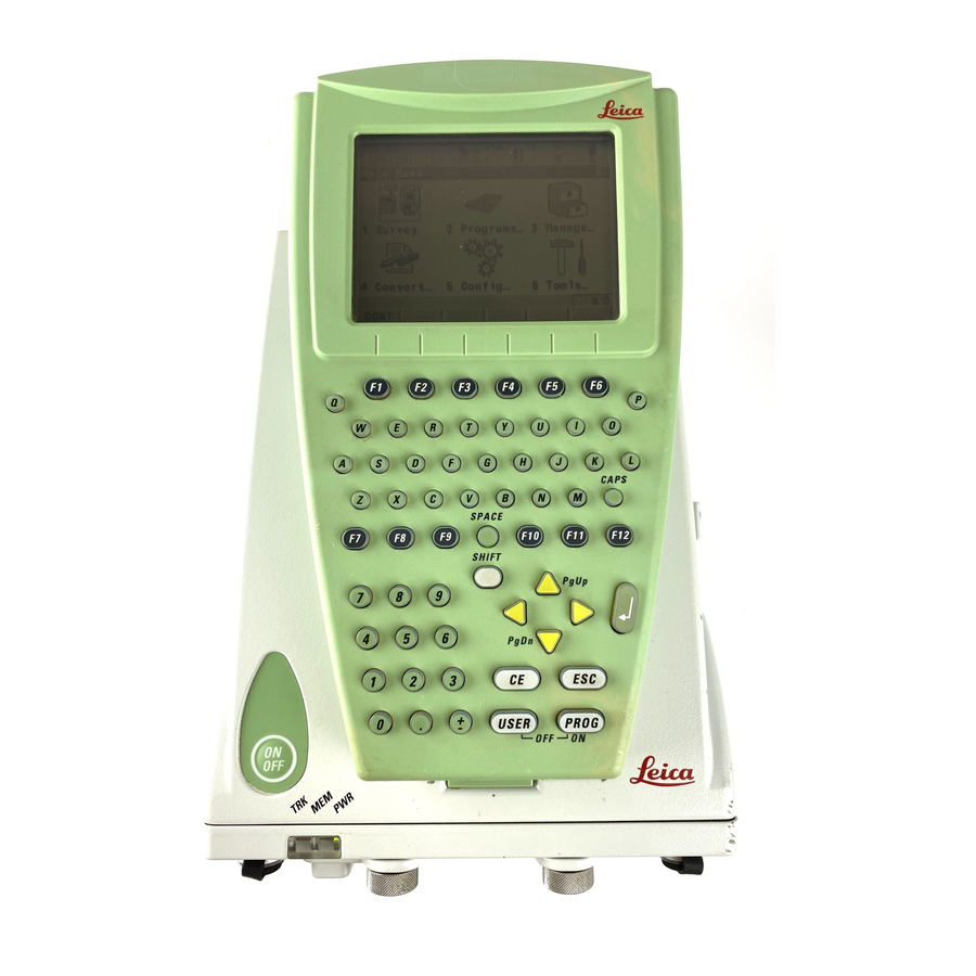
Switching between Leica software and Windows CE desktop Graphic a) Icon to start Leica software b) Windows CE desktop c) Task bar d) Start button RX12_33 Access Leica software THEN RX1250 is started the Leica software starts up automatically. Windows CE desktop double click to display the Leica software. - Page 114 SmartRover in the task bar to maximise it. Access Windows CE THEN desktop Leica software is to be minimised SHIFT MINIM (F5) in Main Menu. Leica software is to be closed SHIFT EXIT (F6) in Main Menu. Windows CE task bar is to be displayed...
-
Page 115: Sleep Mode
In sleep mode, the RX1250 shuts down and reduces power consumption. Rebooting RX1250 from sleep mode is quicker than a cold start after turning off. Putting RX1250 into The RX1250 can only be put into sleep mode in the Main Menu screen. sleep mode Press SHIFT SLEEP (F3). Using RX1250 GPS1200... -
Page 116: Configuring Interfaces
Using RX1250 GPS1200 Configuring Interfaces 4.4.1 Overview Description The required interface configurations for the RX1250 depend on the type of equipment setup. Equipment setup Interface configurations Refer to chapter Real-Time Reference using SmartAn- • SmartAntenna interface via Blue- 4.4.2 tenna, RX1250 and GHT56 tooth or USB •... -
Page 117: Configuring Smartantenna Interface
Highlight the SmartAntenna to be used. CONT (F1) If the SmartAntenna selected is connected for the first time, a Windows CE authen- tication request comes up. Type in 0000 as identification number for Leica’s Blue- tooth and click OK. Using RX1250... - Page 118 Using RX1250 GPS1200 Step Description Once the Bluetooth connection is established, the Bluetooth LED on the SmartAn- tenna starts flashing in blue.
-
Page 119: Configuring Clip-On Interface
4.4.3 Configuring Clip-On Interface Configuration step-by- Step Description step Select Main Menu: Config...\Interfaces... in the Leica software. Highlight Real-Time. EDIT (F3) CONFIGURE Real-Time Mode <R-Time Mode: Rover> or <R-Time Mode: Reference> <Port: Clip-on> DEVCE (F5) to select the device attached to the GHT56. -
Page 120: Receiver Protection With Pin
Description The receiver can be protected by a Personal Identification Number. If the PIN protection is activated, the receiver prompts for PIN code entry after starting up and before GPS1200 Main Menu comes up. If a wrong PIN has been typed in five times, a Personal UnblocKing code is required. - Page 121 PIN code must be typed in within five attempts or the PUK code is required. Next step IF the PIN code THEN entered is correct GPS1200 Main Menu is displayed. Refer to "7 Main Menu". Receiver Protection with PIN GPS1200...
- Page 122 GPS1200 IF the PIN code THEN entered is wrong refer to paragraph "GPS1200 Enter Security PIN Code Error: 479". wrong the fifth time the PUK code is required. Refer to paragraph "GPS1200 Enter Security PIN Code Error: 478". GPS1200 Enter Security PIN...
- Page 123 IF the PIN code THEN entered is wrong the fifth time the PUK code is required. Refer to paragraph "GPS1200 Enter Security PIN Code Error: 478". GPS1200 Enter Security PIN Code Error: 478 OK (F4) To continue with the subsequent screen.
- Page 124 Description of fields Field Option Description PUK Code User input The PUK code as generated by Leica Geosystems. • For receivers delivered with firmware version 2.10 or higher, the PUK code comes with the receiver. • For receivers delivered with firmware versions lower than v2.10, contact a Leica representative to...
- Page 125 PIN code is cleared and the PIN protection is deactivated. GPS1200 Main Menu is displayed. Refer to "7 Main Menu". wrong GPS1200 keeps asking for the correct PUK code. SHIFT QUIT (F6) to turn off the receiver.
-
Page 126: Configurable Keys
Define hot key step-by- This step-by-step description shows how to assign the CONFIGURE Coding & Linework step screen to the F7 key and to the first line of GPS1200 User Menu: Job Name. Step Description Select Main Menu: Config...\General Settings...\Hot Keys & User Menu. - Page 127 For Hot Keys/Shift Hot Keys select <F7: CONF Coding & Linework Settings>. For User Menu select <1: CONF Coding & Linework Settings>. CONT (F1) CONT (F1). Press F7 to access CONFIGURE Coding & Linework. Press USER and 1 to access CONFIGURE Coding & Linework. Configurable Keys GPS1200...
-
Page 128: User Key
Access Press USER to access GPS1200 User Menu: Job Name. GPS1200 This is an example of what a user defined menu can look like. The softkeys and their order User Menu: Job Name is fixed. - Page 129 Define USER key step- To define the USER key is the same as for the hot keys. Refer to paragraph "Define hot key by-step step-by-step". Configurable Keys GPS1200...
-
Page 130: Main Menu
The main menu is normally the first screen displayed when the instrument is switched on. If the PIN protection is active, GPS1200 Enter Security PIN Code is displayed first. After typing in the correct PIN code, the main menu is displayed. - Page 131 Tools... • To format the memory device. • To upload files relevant for the receiver func- tionality, for example, firmware and language files. • To transfer non data related files between receiver and CompactFlash card. Main Menu GPS1200...
- Page 132 Main Menu GPS1200 Main menu function Description Refer to chapter • To perform arithmetic operations such as addi- tion, subtraction, multiplication, division, statis- tical functions, trigonometric functions, conver- sions or roots. • To view files on the CompactFlash card or the internal memory.
-
Page 133: Survey
CSYS (F6) To change the coordinate system. Refer to "13.4.1 Creating a New Coordinate System" for information on defining a coordinate system. Next step For Main Menu: Survey Refer to chapter 44. Main Menu GPS1200... -
Page 134: Programs
Select Main Menu: Programs..Press PROG. Description Programs... accesses the application programs menu. The screen of the application programs menu is called GPS1200 Programs. GPS1200 The application programs menu contains all loaded application programs including Survey. Programs They are listed in the order in which they were loaded. - Page 135 For Main Menu: Programs...\Determine Coordinate System Refer to chapter 38. For Main Menu: Programs...\Volume Calculations Refer to chapter 49. For Main Menu: Programs...\Wake-Up Refer to chapter 49. For Main Menu: Programs...\RoadRunner Refer to GPS1200 Road- Runner Manual. Main Menu GPS1200...
-
Page 136: Manage
Main Menu GPS1200 Manage... Access Select Main Menu: Manage..Description Manage... is used to manage • jobs. • coordinate systems. • data. • configuration sets. • codelists. • antennas. Management functions include creating, selecting, editing and deleting. GPS1200 Management CONT (F1) To select the highlighted option and to continue with the subsequent screen. - Page 137 For Main Menu: Manage...\Coordinate Systems Refer to chapter 13. For Main Menu: Manage...\Configuration Sets Refer to chapter 14. For Main Menu: Manage...\Antennas Refer to chapter 15. Main Menu GPS1200...
-
Page 138: Convert
Main Menu GPS1200 Convert... Access Select Main Menu: Convert..Description Convert... provides access to data exchange options. GPS1200 Convert Data CONT (F1) To select the highlighted option and to continue with the subsequent screen. Next step For Main Menu: Convert...\Export Data from Job Refer to chapter 16. -
Page 139: Config
Press USER and then CONF (F2). Description Config... accesses all configuration parameters related to a survey, the receiver and the interfaces. Any changes made are stored in the configuration set. GPS1200 Configuration: Configu- ration Set CONT (F1) To select the highlighted option and to continue with the subsequent screen. -
Page 140: Tools
Main Menu GPS1200 Tools... Access Select Main Menu: Tools..Description Tools... provides functionality which is not directly related to surveying data. GPS1200 Tools Menu CONT (F1) To select the highlighted option and to continue with the subsequent screen. Next step For Main Menu: Tools...\Format Memory Device... - Page 141 Main Menu GPS1200...
- Page 142 • DTM jobs. Refer to "43.4.4 Staking Out a DTM". • Road jobs. Refer to the GPS1200 RoadRunner Manual. Default job A job called Default is available on the receiver after formatting the memory device, inserting a previously formatted CompactFlash card or deleting all jobs from MANAGE Jobs (Device).
-
Page 143: Manage
NEW (F2) To create a job. Refer to "8.3 Creating a New Job". EDIT (F3) To edit the highlighted job. Refer to "8.4 Editing a Job". DEL (F4) To delete the highlighted job. Manage...\Jobs GPS1200... - Page 144 Manage...\Jobs GPS1200 CFCRD (F6) or INTL (F6) Available for receivers with internal memory. To change between viewing jobs stored on the CompactFlash card or internal memory. Next step IF a job THEN is to be selected highlight the desired job.
-
Page 145: Creating A New Job
NEW (F2) to access MANAGE New Job. STORE (F1) To store the settings and to return to the screen from where MANAGE New Job was accessed. PAGE (F6) To change to another page on this screen. Manage...\Jobs GPS1200... - Page 146 Manage...\Jobs GPS1200 Step Description Refer to chapter MANAGE New Job, General page <Name:> A unique name for the new job. The name may be up to 16 characters long and may include spaces. Input required. <Description:> Two lines for a detailed description of the job. This can be for example, work to be performed or the classes contained in the job.
- Page 147 • For <Averaging Mode: Absolute Diffs>: <Points to Use:> The type of points which will be taken into account for absolute differences. From <Easting:> to <Cartesian Z:> The acceptable absolute differences for each coordinate component. Manage...\Jobs GPS1200...
- Page 148 Manage...\Jobs GPS1200 Step Description Refer to chapter • For <Averaging Mode: Off>: No other fields are available. STORE (F1) creates the new job and returns to MANAGE Jobs (Device).
-
Page 149: Editing A Job
SHIFT LOG (F5) accesses MANAGE Data Log: Job Name. To view, edit and delete points, lines and areas stored with the job. Points, lines and areas are sorted by time in one list. PAGE (F6) changes to the Codelist page. Are codes stored in the job? Manage...\Jobs GPS1200... - Page 150 Manage...\Jobs GPS1200 Step Description Refer to chapter • If no, continue with step 6. • If yes, continue with step 8. No codes are stored in the job. MANAGE Edit Job: Job Name, Codelist page <Codelist: <None>> This default setting can be changed. Choosing a codelist copies the codes to the job.
- Page 151 Points, lines and areas are sorted by time in one list. STORE (F1) stores the changes and returns to the screen from where MANAGE Edit Job: Job Name was accessed. Manage...\Jobs GPS1200...
-
Page 152: Managing Job Codes
Manage...\Jobs GPS1200 Managing Job Codes Description To view, edit, group and sort all codes currently stored in the job. The functionality of this screen is mainly the same as for MANAGE Codes. For simplicity, the functionality which is different from MANAGE Codes is explained here. Refer to "10.5 Managing Codes" for infor- mation on MANAGE Codes. -
Page 153: Manage
To access MANAGE Code Groups. To view, create, activate and deactivate code groups. Refer to "10.6 Managing Code Groups". SHIFT SORT (F5) To access MANAGE Sort Codes. To sort codes by code name, code description, quick code or last used. Manage...\Jobs GPS1200... - Page 154 Manage...\Jobs GPS1200 Next step THEN the job codes do not CONT (F1) closes the screen and returns to the screen from where need to be changed MANAGE Job Codes was accessed. a new job code is to NEW (F2). Refer to "10.5.2 Creating a New Code".
- Page 155 The line style can be changed. This new line style is stored to the Area codes code. It can be decided whether or not to update the line style of all previously stored lines/areas with this code in this job. Manage...\Jobs GPS1200...
-
Page 156: Overview
Manage...\Data GPS1200 Manage...\Data Overview Description Data is a generic term for points, lines and areas. Data management is the administration of data stored in the active job. This includes • viewing data with their related information. • editing data. •... -
Page 157: Accessing Data Management
Press USER. Refer to "6.2 USER Key" for information on the USER key. From a choicelist in some screens for example in application programs. Tap the line/area icon. Refer to the GPS1200 System Field Manual for information on icons. The objects listed on the pages belong to the currently active job. The objects listed and their order depend on the active sort and filter settings. - Page 158 Manage...\Data GPS1200 MANAGE CONT (F1) Data: Job Name, To close the screen and return to the screen from where this screen was accessed. Points page NEW (F2) To create a point. EDIT (F3) To edit the highlighted point. DEL (F4) To delete the highlighted point.
- Page 159 To create a line/area. After storing the new line/area, all existing lines and areas which are open are closed. EDIT (F3) To edit the highlighted line/area. CLOSE (F4) and OPEN (F4) To change between the options in the Open column of the highlighted line/area. Manage...\Data GPS1200...
- Page 160 Manage...\Data GPS1200 MORE (F5) To display information about the codes if stored with any line/area, the start time, the end time of when the last point was added to the line/area, the length of the line, the perimeter and the area of the area.
- Page 161 Line ID or MANAGE Edit Area: Area ID. Refer to "9.4.3 Editing a Line/Area". is to be viewed PAGE (F6) until the Map page is active. Refer to "32.5 Map Mode" for information about the functionality and softkeys available on the Map page. Manage...\Data GPS1200...
-
Page 162: Point Management
Manage...\Data GPS1200 Point Management 9.3.1 Terminology Description This chapter describes technical terms related to data management. Coordinate triplet A measured point consists of three coordinate components - two horizontal components and one vertical component. The generic term for the three coordinate components is coordinate triplet. - Page 163 Multiple. With more than one measured coordinate triplet, the average for the position and the height can be computed. Type Navigated points using uncorrected code solutions of a single epoch or SPP positions. Instrument source Number of triplets Multiple Manage...\Data GPS1200...
- Page 164 Manage...\Data GPS1200 Class Characteristic Description Type Estimated points from LGO. Instrument source LGO. Possible number of triplets NONE Type Measured points with angles. Instrument source Possible number of Unlimited triplets Sub class The sub class describes certain classes in detail. It indicates the status of the position when a coordinate triplet was measured and how the coordinates were determined.
- Page 165 Source Originated from application program/function- Instrument ality source ASCII File Convert Data, Import ASCII/GSI Data to Job GPS or TPS Arc Base Pt COGO, Arc Calculation - Base Point GPS or TPS Manage...\Data GPS1200...
- Page 166 Manage...\Data GPS1200 Source Originated from application program/function- Instrument ality source Arc Centre Pt COGO, Arc Calculation - Centre Point GPS or TPS Arc Offset Pt COGO, Arc Calculation - Offset Point GPS or TPS Arc Segmt Pt COGO, Arc Calculation - Segmentation...
- Page 167 Reference Plane, scan Road Runner Road Runner GPS or TPS Sets of Angles Sets of Angles Setup (Known BS) Setup, Known Backsight Point Setup (Loc Rsct) Setup, Local Resection Setup (Ori&Ht) Setup, Orientation and Height Transfer Setup (Resect) Setup, Resection Manage...\Data GPS1200...
- Page 168 Manage...\Data GPS1200 Source Originated from application program/function- Instrument ality source Setup (Resect H) Setup, Resection Helmert Setup (Set Az) Setup, Set Azimuth Srvy Auto Offset Survey Auto Points, automatically recorded with GPS or TPS offsets Stakeout Stakeout GPS or TPS...
- Page 169 The standard deviation as CQ would often be too optimistic. This is why the computation of the CQ in GPS1200 is not simply based on the basic standard deviation algorithms. For the standard deviation, there is, statistically, a 39.3 % probability in 2D that the computed position deviates from the true position by less than the standard deviation.
- Page 170 Manage...\Data GPS1200 Computation GPS measurements Unknowns Least square adjustment like rover coordinates Elements of cofactor matrix Root Mean Square RMS = a posteriori of unit weight • Reflects the influence of the different constellations of the • Reflects all error sources such as...
- Page 171 For the height determination, satellites can appear in two quadrants. This weakens the height position compared to the plan position. GPS12_055 Position determination with satellites Height determination with satellites appearing in all four quadrants. appearing in two quadrants. Manage...\Data GPS1200...
-
Page 172: Creating A New Point
Manage...\Data GPS1200 9.3.2 Creating a New Point Access Refer to "9.2 Accessing Data Management" to access MANAGE Data: Job Name. Create point step-by- The following table explains the most common settings. Refer to the stated chapter for more step information on screens. - Page 173 The codes from the job codelist are used. <Point Code:> All point codes of the job codelist can be selected. The description of the code is shown as an output field. The attributes are shown as output, input or choicelist fields depending on their definition. Manage...\Data GPS1200...
- Page 174 Manage...\Data GPS1200 Step Description Refer to chapter • For <Thematc Codes: Without Codelist>: Codes for points can be typed in but not selected from a codelist. <Code:> The code to be stored with the point. A check is performed to see if a point code of this name already exists in the job.
- Page 175 It may happen that a point with the same point ID exists in the job. If 11.5 the codes and/or attribute values of the new and the existing point do not match, a screen opens where they can be corrected. Manage...\Data GPS1200...
-
Page 176: Editing A Point
Manage...\Data GPS1200 9.3.3 Editing a Point Access Refer to "9.2 Accessing Data Management" to access MANAGE Data: Job Name. Edit point step-by-step The following table explains the most common settings. Refer to the stated chapter for more information on screens. - Page 177 The name of the station from where the point was measured is shown in an output field. Changing the reflector height recalculates the point height. MORE (F5) Available for TPS points. Displays the horizontal angle or the azimuth from the point to the instrument. Manage...\Data GPS1200...
- Page 178 Manage...\Data GPS1200 Step Description Refer to chapter PAGE (F6) changes to the Code page. MANAGE Edit Point: Point ID, Code page 11.2 and 11.3 The point code can be edited. All point codes in the job can be selected. The description of the code is shown as an output field.
- Page 179 MANAGE Edit Point: Point ID, Mean page 9.3.4 All points of <Class: MEAS> of the same point ID are listed sorted by time. The settings in the Use column can be edited. All functionality and keys are explained in a separate section. Manage...\Data GPS1200...
- Page 180 Manage...\Data GPS1200 Step Description Refer to chapter STORE (F1) stores the changes and returns to MANAGE Data: Job Name. An edited point retains the creation value for <Time:>. Changing coordinates of a point which has been previously used in other application programs, for example COGO, or hidden point measurements does not update the application results.
-
Page 181: Mean Page
Defining the averaging mode and configuring the limits The averaging mode and the limits are configured in MANAGE New Job, Avge page or in MANAGE Edit Job: Job Name, Avge page. Refer to "8.3 Creating a New Job". Refer to "8.4 Editing a Job". Manage...\Data GPS1200... - Page 182 Manage...\Data GPS1200 Description of averaging modes Averaging Description mode Average When more than one measured coordinate triplet is recorded for the same point, the average for the position and the height is computed. The class AVGE is assigned to the averaged point.
- Page 183 Mode: Rover>. Step Description Main Menu: Survey to access SURVEY Survey Begin. CONT (F1) to access SURVEY Survey: Job Name, Survey page. SHIFT AVGE (F2) or SHIFT ABS (F2) to access SURVEY Edit Point: Point ID, Mean page. Manage...\Data GPS1200...
- Page 184 Manage...\Data GPS1200 MANAGE All measured coordinate triplets recorded using the same point ID are shown. Edit Point: Point ID, Mean page STORE (F1) To store the changes and to return to the screen from where this screen was accessed. USE (F2) To change between the options in the Use column for the highlighted coordinate triplet.
- Page 185 The use of a measured coordinate triplet in the averaging. • Auto The coordinate triplet is included in the averaging computation if within the averaging limit defined in MANAGE New Job, Avge page or in MANAGE Edit Job: Job Name, Avge page. Manage...\Data GPS1200...
- Page 186 Manage...\Data GPS1200 Column Description • The coordinate triplet is always included in the averaging computation even if it would fall outside the averaging limit defined in MANAGE New Job, Avge page or in MANAGE Edit Job: Job Name, Avge page.
- Page 187 Next step IF a measured coor- THEN dinate triplet is not to be viewed STORE (F1) stores the changes and returns to MANAGE Data: Job Name. is to be viewed highlight a measured coordinate triplet and EDIT (F3). Manage...\Data GPS1200...
-
Page 188: Line/Area Management
Manage...\Data GPS1200 Line/Area Management 9.4.1 Overview Description A line/area consists of points and can be created/edited in MANAGE Data: Job Name. The individual points are measured within any application program. These can be all points except auxiliary points. Points can be simultaneously assigned to one or more lines and/or areas. -
Page 189: Creating A New Line/Area
• To start a new sequence of line ID’s type over the line ID. • For an individual name independent of the ID template SHIFT INDIV (F5). SHIFT RUN (F5) changes back to the next ID from the configured ID template. Manage...\Data GPS1200... - Page 190 Manage...\Data GPS1200 Step Description Refer to chapter <Pts to Store:> The type of points which are used to form the line 45.1, 45.4 during a survey. Select between all points, measured points, auto points and offset points of type 1 or 2.
- Page 191 LAST (F4) recalls the last used attribute values which were stored with this line code. DEFLT (F5) recalls the default attribute values for the selected code. STORE (F1) stores the new line entered and all associated informa- tion and returns to MANAGE Data: Job Name, Lines (X) page. Manage...\Data GPS1200...
- Page 192 Manage...\Data GPS1200 Step Description Refer to chapter The value for <Start Time:> with which the line is stored is the time 9.4.3 when STORE (F1) was pressed. The same value is assigned to the value for <End Time:> until a point is added to the line.
-
Page 193: Editing A Line/Area
<No. of Pts:> The number of points contained within the line. <Length:> The sum of the distances between the points in the sequential order in which they are stored for the line. This can be a horizontal grid distance or a geodetic distance on the WGS 1984 ellipsoid. Manage...\Data GPS1200... - Page 194 Manage...\Data GPS1200 Step Description Refer to chapter <Start Time:> and <Start Date:> The time/date when the line was created. A line cannot be renamed to an already existing line ID. MORE (F5) displays <End Time:> and <End Date:>. This is the time/date when the last point was added to the line.
- Page 195 STORE (F1) stores the changes and returns to MANAGE Data: Job Name, Lines (X) page. An edited line retains the creation value for <Start Time:>. The value for <End Time:> changes when a point was added to the line. Manage...\Data GPS1200...
-
Page 196: Working Example
Manage...\Data GPS1200 9.4.4 Working Example Description Application: Pick up points along fence lines with a gate. The gate can also be represented as a line. Some points belong to more than one line. Working technique: Real-time kinematic. Setting: F7 is configured to access the MANAGE Data: Job Name screen. - Page 197 Points can be coded separately. Press F7. MANAGE Data: Job Name, Lines (X) page Highlight the line F2. OPEN (F4) to open the line. Highlight the line G1. OPEN (F4) to open the line. Line F1 stays open. Manage...\Data GPS1200...
- Page 198 Manage...\Data GPS1200 Step Description Refer to chapter CONT (F1) SURVEY Survey: Job Name 44.3.3 Measure P1. This point is automatically added to all three lines open at that time. Press F7. MANAGE Data: Job Name, Lines (X) page Highlight the line F1.
-
Page 199: Data Log
SHIFT LOG (F5) to access MANAGE Data Log: Job Name. Access by hot key Press a hot key configured to access the screen MANAGE Data Log: Job Name. Refer to "6.1 Hot Keys" for information on hot keys. Manage...\Data GPS1200... - Page 200 Manage...\Data GPS1200 Access by user defined menu Press USER. Refer to "6.2 USER Key" for information on the USER key. MANAGE In the column Data Record, all points, lines and areas as well as free codes stored within Data Log: Job Name the active job are displayed.
- Page 201 Next step CONT (F1) returns to the screen from where MANAGE Data Log: Job Name was accessed. Manage...\Data GPS1200...
-
Page 202: Point Sorting And Filters
Manage...\Data GPS1200 Point Sorting and Filters 9.6.1 Sorting and Filters for Points, Lines and Areas Description The sort settings define the order of the objects in the active job. The filter settings define the objects to be viewed. Three types of filters are available:... - Page 203 The selected sort and filter settings are applied. STAKE (F5) To filter points for the Stakeout application program. Refer to "9.6.3 Stakeout Filter". PAGE (F6) To change to another page on this screen. Manage...\Data GPS1200...
- Page 204 Manage...\Data GPS1200 Description of fields Field Option Description <Sort:> Ascend Point ID, Always available. The method points are sorted by. Descend Point ID, Forward Time or Backward Time <Filter:> Always available. The method the points are filtered No Filter Shows all points.
- Page 205 Available for <Filter: Time>. The time of the first point to be displayed. <End Date:> User input Available for <Filter: Time>. The date of the last point to be displayed. <End Time:> User input Available for <Filter: Time>. The time of the last point to be displayed. Manage...\Data GPS1200...
- Page 206 The coordinate triplets of the highest class are shown. All Triplets All classes for one coordinate triplet are shown. <Instrument:> All, TPS, GPS, Available for <Filter: Instrument>. Points originating LEICA Geo Office, from this instrument type are shown. Level, Data Logger, Third Party SW or Unknown <Type:>...
- Page 207 Choicelist Available for <Filter: Individual Area>. Opening the choicelist opens MANAGE Data: Job Name. Refer to "9.2 Accessing Data Management". Next step PAGE (F6) changes to the Lines page. Refer to paragraph "MANAGE Sorts & Filters, Lines page". Manage...\Data GPS1200...
- Page 208 Manage...\Data GPS1200 MANAGE Sorts & Filters, Lines page CONT (F1) To close the screen and return to the screen from where this screen was accessed. The selected sort and filter settings are applied and the lists in MANAGE DATA: Job Name are updated.
- Page 209 PAGE (F6) To change to another page on this screen. Description of fields The functionality of setting the filters is identical to those on the Lines page. Refer to para- graph "MANAGE Sorts & Filters, Lines page". Manage...\Data GPS1200...
- Page 210 Manage...\Data GPS1200 Next step CONT (F1) returns to the screen from where MANAGE Sorts & Filters was accessed.
-
Page 211: Point, Line And Area Code Filter
To activate and deactivate code groups. Accesses MANAGE Code Groups. Any code group that have been previously deactivated are displayed as deactivated here. Codes belonging to a deactivated code group are not displayed in MANAGE Code Filter. Refer to "10.6 Managing Code Groups". Manage...\Data GPS1200... - Page 212 Manage...\Data GPS1200 USE (F5) To activate and deactivate the filter for the highlighted code. NONE (F6) or ALL (F6) To deactivate or activate all point codes. SHIFT SORT (F5) To define the order of the codes. Accesses MANAGE Sort Codes.
-
Page 213: Stakeout Filter
In MANAGE Sorts & Filters, PAGE (F6) until the Points page is active. STAKE (F5) to access MANAGE Stakeout Filter. MANAGE Stakeout Filter CONT (F1) To close the screen and return to the screen from where this screen was accessed. Manage...\Data GPS1200... - Page 214 Manage...\Data GPS1200 Description of fields Field Option Description <View:> Shows all points. Pts to Stakeout Shows points not yet staked out. Staked Points Shows points which are already staked out.
- Page 215 Manage...\Data GPS1200...
-
Page 216: Terminology
Manage...\Codelists GPS1200 Manage...\Codelists 10.1 Terminology Description This chapter describes technical terms related to codes and codelists. The values for code groups, codes and attributes are case sensitive. For example the code group Tree is not the same as the code group TREE. - Page 217 It allows to export free codes and objects in a chronological order to be used for third party mapping software. Code type: Code type: Free code Point code Line code Area code Optional: Optional: Quick code Quick code Manage...\Codelists GPS1200...
- Page 218 Manage...\Codelists GPS1200 Code types The code type defines how and for which objects a code can be used. It is possible to create a code of the same name but of different code types both on the receiver and in LGO.
- Page 219 This attribute value is automatically attached to the code. New attributes with this attribute type can be created in LGO. Attribute value types The attribute value type defines which values are accepted as input. Manage...\Codelists GPS1200...
- Page 220 Manage...\Codelists GPS1200 Text: Any input for the attribute is interpreted as text. New attributes with this attribute value type can be created in LGO or on the receiver. Real: An input for the attribute must be a real number, for example 1.23. New attributes with this attribute value type can be created in LGO.
- Page 221 Codelist Description A codelist is a collection of codes that can be used to describe surveyed objects in the field. Elements of a codelist • Code group • Code • Attributes Manage...\Codelists GPS1200...
- Page 222 Manage...\Codelists GPS1200 Structure of a codelist Structure Example Codelist Codelist |—— Code group 1 |—— Trees |—— Code 1.1 |—— Birch |—— Attribute 1.1.1 |—— Height |—— Attribute ... |—— Condition |—— Attribute 1.1.20 |—— Remark |—— Code 1.2 |—— Oak |——...
-
Page 223: Overview
The creating, editing and managing of codelists is explained in this chapter. In order to use a codelist on the receiver, it must be transferred from the CompactFlash card to the System RAM. Refer to "26 Tools...\Transfer Objects...". Manage...\Codelists GPS1200... -
Page 224: Accessing Codelist Management
Manage...\Codelists GPS1200 10.3 Accessing Codelist Management Access Select Main Menu: Manage...\Codelists. From a choicelist in some screens, for example MANAGE New Job, Codelist page. MANAGE Listed are all codelists stored in the System RAM. Codelists CONT (F1) To return to the screen from where this screen was accessed. - Page 225 MANAGE Codelists was accessed. is to be created NEW (F2). Refer to "10.4 Creating/Editing a Codelist". is to be edited highlight the codelist and EDIT (F3). Refer to "10.4 Creating/Editing a Codelist". Manage...\Codelists GPS1200...
-
Page 226: Creating/Editing A Codelist
Manage...\Codelists GPS1200 10.4 Creating/Editing a Codelist Access Refer to "10.3 Accessing Codelist Management" to access MANAGE Codelists. Create/edit a codelist The following table explains the most common settings. Refer to the stated chapter for more step-by-step information on screens. Step... -
Page 227: Managing Codes
The listed code groups belong to the selected System RAM codelist when this screen was accessed through Main Menu: Manage...\Codelists. to the job codelist when MANAGE Codes was accessed from an application program, MANAGE New Job or MANAGE Edit Job. Manage...\Codelists GPS1200... - Page 228 Manage...\Codelists GPS1200 The indicates codes which have attributes attached. CONT (F1) To close the screen and return to the screen from where this screen was accessed. NEW (F2) To create a new code. Refer to "10.5.2 Creating a New Code".
- Page 229 NEW (F2). Refer to "10.5.2 Creating a New Code". created a code is to be edited highlight the code and EDIT (F3). Refer to "10.5.3 Editing a Code". code groups are to be SHIFT GROUP (F4). Refer to "10.6 Managing Code Groups". accessed Manage...\Codelists GPS1200...
-
Page 230: Creating A New Code
Manage...\Codelists GPS1200 10.5.2 Creating a New Code Create a new code step- The following table explains the most common settings. Refer to the stated chapter for more by-step information on screens. Step Description Refer to chapter Refer to "10.5.1 Accessing MANAGE Codes" to access MANAGE Codes. - Page 231 <Attribute 1:> can be edited and the attribute value to be used as the default attribute value can be typed in. Attributes of attribute type mandatory or fixed and of value type real or integer must be created in LGO. Manage...\Codelists GPS1200...
- Page 232 Manage...\Codelists GPS1200 Step Description Refer to chapter Up to twenty attributes can be created. Is another attribute to be created? • If yes, repeat step 4. • If no, continue with step 6. STORE (F1) adds the new code and any associated attributes to the System RAM codelist and returns to the screen from where this screen was accessed.
-
Page 233: Editing A Code
All following steps are identical with the creation of a new code. Refer to "10.5.2 Creating a New Code". Follow the instructions in paragraph "Create a new code step-by-step" from step 3. onwards. Attribute names that have already been typed in cannot be edited in a job codelist. Manage...\Codelists GPS1200... -
Page 234: Managing Code Groups
Manage...\Codelists GPS1200 10.6 Managing Code Groups Access step-by-step Step Description Refer to "10.5.1 Accessing MANAGE Codes" to access MANAGE Codes. SHIFT GROUP (F4) to access MANAGE Code Groups. MANAGE The listed code groups belong to Code Groups the selected System RAM codelist when this screen was accessed through Main Menu: Manage...\Codelists. - Page 235 MANAGE Code Groups. is to be edited highlight the code group and EDIT (F3). In MANAGE Edit Code Group type in the changes for <Group:>. STORE (F1) stores the changes and returns to MANAGE Code Groups. Manage...\Codelists GPS1200...
-
Page 236: Coding
A code is a description which can be stored with a point, line, area or alone. Coding on GPS1200 is very flexible with thematical, free and quick coding being available. Thematical and free coding is possible by selecting codes from a codelist or by directly typing in codes. - Page 237 CAD package used, free codes can be configured to be stored before or after the object. Quick Quick coding is the storing of an object plus a thematical or free code using a minimum number of keystrokes. Coding GPS1200...
- Page 238 Coding GPS1200 Coding Characteristic Description method Selection of the codes Shortcuts must be assigned to codes in the job codelist. <Quick Code: On> must be set in CONFIGURE Coding & Linework. Typing the shortcut searches for the assigned code. Point occu- pation begins.
-
Page 239: Thematical Coding
Open the choicelist for <Point Code:> in MANAGE Edit Point: Point ID, Code page in data management. The procedure is similar for lines and areas. Open the choicelist for <Code (Auto):> in SURVEY Survey: Job Name, Auto page, if configured. Coding GPS1200... - Page 240 Coding GPS1200 MANAGE MANAGE Select Code is shown as an example. Select Code CONT (F1) To return to the screen from where this screen was accessed. NEW (F2) To create a new code. Refer to "10.5.2 Creating a New Code".
- Page 241 ID template. The occupied point is assigned to that line. The line stays open until it is closed manually or another line code is selected. • If an area code is selected then the behaviour is as for lines. ATRIB (F3) XX Enter Attributes Coding GPS1200...
- Page 242 Coding GPS1200 Step Description Refer to chapter If configured for the selected code, input fields for attribute values are available. Type in the attribute values. Attribute values for attributes of type • normal can be typed in. • fixed cannot be edited.
- Page 243 If a point with the same point ID exists in the job, the codes, the 11.5 attribute names and the attribute values of the new and the existing point must be identical. Should they not be identical, a screen opens where the code or attribute mismatch can be corrected. Coding GPS1200...
-
Page 244: Thematical Coding Without Codelist
Coding GPS1200 11.2.2 Thematical Coding without Codelist Requirements • <Thematc Codes: Without Codelist> in CONFIGURE Coding & Linework. • A display mask with an input field for codes must be configured. • A display mask with an choicelist for code types must be configured. - Page 245 • If an area code is selected then the behaviour is as for lines. OCUPY (F1) to start the point occupation. PAGE (F6) to change to another page on this screen. Coding GPS1200...
-
Page 246: Free Coding
Coding GPS1200 11.3 Free Coding 11.3.1 Free Coding Using a Codelist In this chapter, free coding using a codelist is explained for points. Refer to "9.4 Line/Area Management" for information on coding lines/areas. Requirements • The job codelist contains free codes. - Page 247 SHIFT GROUP (F4) To view, create, delete, activate and deactivate code groups. Refer to "10.6 Managing Code Groups". SHIFT SORT (F5) To sort codes by code name, code description, quick code or the last used. Coding GPS1200...
- Page 248 Coding GPS1200 Free coding using a The following table explains the most common settings. Refer to the stated chapter for more codelist step-by-step information on screens. Step Description Refer to chapter Refer to paragraph "Access" to access FREECODE Select Free Code.
- Page 249 DEFLT (F5) recalls the default attribute values for the selected code. FREECODE Enter Attributes STORE (F1) returns to the screen from where FREECODE Select Free Code was accessed and stores the free code, any associated attribute values and time related information. Coding GPS1200...
-
Page 250: Free Coding With Direct Input
Coding GPS1200 11.3.2 Free Coding with Direct Input In this chapter, free coding with direct input is explained for points. Refer to "9.4 Line/Area Management" for information on coding lines/areas. Requirements A hot key is configured to access the screen FREECODE Enter Free Code & Attributes or the user defined menu is configured to display the option Enter Free Code. - Page 251 The free codes are sorted by time with the most recently used code at the top of the list. In FREECODE Last Used Free Codes press ATRIB (F3) to type in attribute values. STORE (F1) stores the free code, any associated attribute values and time related information. Coding GPS1200...
-
Page 252: Quick Coding
Coding GPS1200 11.4 Quick Coding Requirements • The job codelist contains quick codes for points, lines and/or areas. • According to the requirements of the used CAD package, set <Rec Free Code: Before Point> or <Rec Free Code: After Point> in CONFIGURE Coding & Linework. - Page 253 Attribute values for attributes of type • normal cannot be typed in. Depending on the setting for <Attributes:> in CONFIGURE Coding & Linework, the default or the last used attribute values are stored. Coding GPS1200...
- Page 254 Coding GPS1200 Step Description Refer to chapter • fixed cannot be edited. The point code and any associated attribute values are stored with the point. This can be automatic if <Auto STOP: Yes> and <Auto STORE: Yes> is configured or manual with STOP (F1) and STORE (F1).
- Page 255 A new line/area is created and immediately stored with that line/area code and attributes. For the line/area ID, the line/area ID template as defined in CONFIGURE ID Templates is used. The system asks for mandatory attribute values. Quick coding for a line/area is finished. Coding GPS1200...
-
Page 256: Code And Attribute Mismatch
Coding GPS1200 11.5 Code and Attribute Mismatch 11.5.1 Code Mismatch Description When storing a point with a code, it may happen that a point with the same point ID already exists in the job. If the codes of the new and the existing point do not match, a screen opens where the code can be corrected. - Page 257 Highlight the code to be stored with the new point. STORE (F1) stores the highlighted code and any associated attributes with the point being stored and continues with the application program or data manage- ment. Coding GPS1200...
-
Page 258: Attribute Mismatch
Coding GPS1200 11.5.2 Attribute Mismatch Description If a point with the same point ID exists in the job, the codes, the attribute names and the attribute values of the new and the existing point must be identical. Should they not be iden- tical, a screen opens where the attribute mismatch can be corrected. - Page 259 CURNT (F5) and STORD (F5) to display the attribute names and values to be stored with the point. STORE (F1) stores the displayed attribute names and values with the point being stored and continues with the application program or data management. Coding GPS1200...
-
Page 260: Linework
Linework GPS1200 Linework 12.1 Overview Description Working with lines can be automated. Two ways of working are available. They are listed in the table below. The two ways of working can be mixed. Linework by Description Linework In all application programs and on the Auto page in Survey, a display mask listbox can be configured to show a field <Linework:>... -
Page 261: Performing Linework
Select Main Menu: Survey to access SURVEY Survey Begin. In SURVEY Survey Begin select a job. Select a configuration set with <R-Time Mode: None> or <R-Time Mode: Rover>. Select an antenna. CONT (F1) to access SURVEY Survey: Job Name. Linework GPS1200... - Page 262 Linework GPS1200 SURVEY The most important keys are explained. For the explanation of the other keys refer to "44.3.3 Survey: Job Name, Real-Time Rover Operations". Survey page OCUPY (F1) To start recording positions. The position mode icon changes to the static icon. (F1) changes to STOP.
- Page 263 Any line/area which is currently open is closed and the last point belonging to that line/area is given the End Line/Close Area linework flag. Linework GPS1200...
- Page 264 Linework GPS1200 Field Option Description ReOpen Last Line Opens the last used line again. The last code used with the reopened line is automatically selected when the point is stored. End Line Closes all open lines. Cont Line/Area Indicates a line/area is open.
- Page 265 Depending on the option selected for <Linework:>, a line/area is opened, closed or re-opened. Repeat steps 1. to 5. until all points are occupied. SHIFT QUIT (F6) to exit the Survey application program. Use a format file to export the points including the linework flags. Linework GPS1200...
-
Page 266: Combining Linework And Coding
Linework GPS1200 12.3 Combining Linework and Coding Description Linework and coding can be combined. This combination can be useful, because coding, assigning linework flags and opening/closing lines/areas can all be done with one point observation. Combining Linework and coding can only be configured if thematical point codes or if themat- ical point, line and area codes are available for selection. - Page 267 Else the configuration of a field for code types is optional. • Configure in CONFIGURE Coding & Linework, Coding page • <Show Codes: Only Pt Codes> or <Show Codes: All Codes>. • <Thematc Codes: With Codelist> or <Thematc Codes: Without Codelist>. Linework GPS1200...
- Page 268 Linework GPS1200 • In CONFIGURE Coding & Linework Settings, Linework page define the flags for Line- work. • <R-Time Mode: None> or <R-Time Mode: Rover> in CONFIGURE Real-Time Mode. The Survey application program is used here to explain the combination of Linework and Coding.
- Page 269 Type in a code. choicelist. Only point codes are available for selection. <None> to store a point without ----- to store a point without code or to perform Linework code or to perform Linework without coding. without coding. Linework GPS1200...
- Page 270 Linework GPS1200 Step Field Description for thematical coding With codelist Without codelist <Code Type:> Point is displayed. This field is an output field. It can not be changed. <Linework:> Select an option for the Linework flag to be stored with the point.
- Page 271 Select ----- to store a point without Linework. OCUPY (F1) STOP (F1) STORE (F1) For a point code being selected: • The point is stored with the selected code. • Depending on the selection for <Linework:>, a line/area is opened/closed. Linework GPS1200...
- Page 272 Linework GPS1200 Step Field Description for thematical coding With codelist Without codelist • An open line/area is closed when the selection for <Line- work:> was not changed but • the selection for <Code:> was changed. • the same code was re-selected, for example by using the right/left arrow key.
- Page 273 Linework GPS1200...
-
Page 274: Manage
Manage...\Coordinate Systems GPS1200 Manage...\Coordinate Systems 13.1 Overview Description A coordinate system • consists of up to five elements. • allows the conversion from WGS 1984 geodetic or cartesian coordinates to, local carte- sian, geodetic or grid coordinates and back. •... - Page 275 7 parameter transformation: dX, dY, dZ, rx, ry, rz, scale e) Local cartesian: X, Y, Z f) Local ellipsoid g) Local geodetic: Latitude, longitude, ellipsoidal height h) Local projection i) Local grid: Easting, Northing, orthometric height GPS12_083 Manage...\Coordinate Systems GPS1200...
- Page 276 WGS 1984 is the global geocentric datum to which all GPS positioning information is referred WGS 1984 to. WGS 1984 is the default coordinate system on a GPS1200 receiver. It is not possible to manually create a coordinate system called WGS 1984.
-
Page 277: Terminology
The relation between ellipsoidal height and ortho- metric height is Orthometric Height = Ellipsoidal Height - Geoid Separation N a) WGS 1984 ellipsoid b) Geoid P0 Measured point Ellipsoidal height Geoid separation N, is negative when the geoid is below the ellipsoid GPS12_076 Manage...\Coordinate Systems GPS1200... - Page 278 Manage...\Coordinate Systems GPS1200 N value and geoid model The geoid separation (N value) is the distance between the geoid and the reference ellipsoid. It may refer to the WGS 1984 or to the local ellipsoid. It is not a constant except over maybe small flat areas such as 5 km x 5 km.
- Page 279 CSCS models are supported by GPS1200. Their conversion process is as explained in the following table. Any suitable geoid model can be combined with a geodetic CSCS model. Refer to the online help of LGO for more information on CSCS models.
-
Page 280: Accessing Coordinate System Management
Manage...\Coordinate Systems GPS1200 13.3 Accessing Coordinate System Management Access Select Main Menu: Manage...\Coordinate Systems. Press a hot key configured to access the screen MANAGE Coordinate Systems. Refer to "6.1 Hot Keys" for information on hot keys. Press USER. Refer to "6.2 USER Key" for information on the USER key. - Page 281 SHIFT SET-D (F4) Available unless a default coordinate system is highlighted. To turn the highlighted coordinate system into a user defined default coordinate system stored in the receiver. SHIFT DEFLT (F5) To recall the deleted default coordinate systems. Manage...\Coordinate Systems GPS1200...
- Page 282 Manage...\Coordinate Systems GPS1200 Next step IF a coordinate THEN system is to be selected highlight the desired coordinate system. CONT (F1) closes the screen and returns to the screen from where MANAGE Coordinate Systems was accessed. is to be created highlight any coordinate system and NEW (F2).
-
Page 283: Coordinate Systems
NEW (F2) to access MANAGE New Coordinate System. MANAGE New Coordinate System <Name:> A unique name for the new coordinate system. The name may be up to 16 characters long and may include spaces. Manage...\Coordinate Systems GPS1200... - Page 284 Manage...\Coordinate Systems GPS1200 Step Description Refer to chapter <Residuals:> Available for transformations with control points. Manually entered transformations do not have control points. The method by which residuals are distributed throughout the transforma- tion area. The transformation results become more realistic and any strain is dispersed in the transformation.
-
Page 285: Editing A Coordinate System
An additional field is: <Pre Transform:> Available for Twostep transformations. The name of a preliminary 3D transformation which is used together with the selected projection to obtain preliminary grid coordinates to be used for a final 2D transformation. Manage...\Coordinate Systems GPS1200... - Page 286 Manage...\Coordinate Systems GPS1200 Step Description Refer to chapter Make the required changes. STORE (F1) stores the changes and returns to MANAGE Coordi- nate Systems.
-
Page 287: Transformations
Refer to "13.3 Accessing Coordinate System Management" to access MANAGE Coordinate Systems. In MANAGE Coordinate Systems highlight a coordinate system to be edited. EDIT (F3) In MANAGE Edit Coordinate System highlight <Transform:>. ENTER to access MANAGE Transformations. Manage...\Coordinate Systems GPS1200... - Page 288 Manage...\Coordinate Systems GPS1200 MANAGE Listed are all Classic 3D transformations stored in the database DB-X. Any unavailable infor- Transformations mation is shown as -----. CONT (F1) To select the highlighted transformation and to return to the previous screen. NEW (F2) To create a new transformation.
- Page 289 MANAGE Transformations was accessed. is to be created highlight any transformation and NEW (F2). Refer to "13.5.2 Creating a New Transformation". is to be edited highlight the transformation and EDIT (F3). Refer to "13.5.3 Editing a Transformation". Manage...\Coordinate Systems GPS1200...
-
Page 290: Creating A New Transformation
Manage...\Coordinate Systems GPS1200 13.5.2 Creating a New Transformation Classic 3D transformations can be created. Access Refer to "13.5.1 Accessing Transformation Management" to access MANAGE Transforma- tions. Create a transformation The following table explains the most common settings. Refer to the stated chapter for more step-by-step information on screens. - Page 291 Model: Molodensky-Bad>, additional input fields are available. Select at least a height mode and a transformation model. CLEAR (F5) Available for <Transf Model: Molodensky-Bad>. To set the additional input fields to 0. STORE (F1) stores the new transformation and returns to MANAGE Transformations. Manage...\Coordinate Systems GPS1200...
-
Page 292: Editing A Transformation
Manage...\Coordinate Systems GPS1200 13.5.3 Editing a Transformation Access step-by-step Step Description Refer to "13.5.1 Accessing Transformation Management" to access MANAGE Transformations. In MANAGE Transformations highlight a transformation to be edited. EDIT (F3) to access MANAGE Edit Transformation. All following steps are identical with the creation of a new transformation. -
Page 293: Ellipsoids
NEW (F2) To create a new ellipsoid. Refer to "13.6.2 Creating a New Ellipsoid". EDIT (F3) To edit the highlighted ellipsoid. Refer to "13.6.3 Editing an Ellipsoid". DEL (F4) To delete the highlighted ellipsoid. Manage...\Coordinate Systems GPS1200... - Page 294 Manage...\Coordinate Systems GPS1200 SHIFT SET-D (F4) To turn the highlighted ellipsoid into a user defined default ellipsoid stored in the receiver. SHIFT DEFLT (F5) To recall the deleted default ellipsoids. Next step IF an ellipsoid THEN is to be selected highlight the desired ellipsoid.
-
Page 295: Creating A New Ellipsoid
16 characters long and may include spaces. <Axis a:> The semi-major axis a. <1/f:> The reciprocal value of flattening f. Enter a name. STORE (F1) stores the new ellipsoid and returns to MANAGE Ellip- soids. Manage...\Coordinate Systems GPS1200... -
Page 296: Editing An Ellipsoid
Manage...\Coordinate Systems GPS1200 13.6.3 Editing an Ellipsoid Access step-by-step Step Description Refer to "13.6.1 Accessing Ellipsoid Management" to access MANAGE Ellip- soids. In MANAGE Ellipsoids highlight an ellipsoid to be edited. EDIT (F3) to access MANAGE Edit Ellipsoid. All following steps are identical with the creation of a new ellipsoid. Refer to "13.6.2 Creating a New Ellipsoid". -
Page 297: Projections
Refer to "13.3 Accessing Coordinate System Management" to access MANAGE Coordinate Systems. In MANAGE Coordinate Systems highlight a coordinate system to be edited. EDIT (F3) to access MANAGE Edit Coordinate System. In MANAGE Edit Coordinate System highlight <Projection:>. ENTER to access MANAGE Projections. Manage...\Coordinate Systems GPS1200... - Page 298 Manage...\Coordinate Systems GPS1200 MANAGE Listed are all projections stored in the database DB-X. Any unavailable information is shown Projections as -----. CONT (F1) To select the highlighted projection and to return to the previous screen. NEW (F2) To create a new projection. Refer to "13.7.2 Creating a New Projection".
- Page 299 Lambert 2 Para Lambert 2 Parallel. Conformal projection onto a cone, with its axis coinciding with the z-axis of the ellipsoid. The cone is secant to the sphere. Manage...\Coordinate Systems GPS1200...
- Page 300 Manage...\Coordinate Systems GPS1200 Column Option Description Cassini-Soldn Soldner Cassini. Projection onto a cylinder. It is neither equal area nor conformal. The scale is true along the central meridian and along lines perpendic- ular to central meridian. Polar Stereo Polar Stereographic. Conformal azimuthal projection onto a plane.
- Page 301 IF a projection THEN is to be edited highlight the projection and EDIT (F3). Refer to "13.7.3 Editing a Projection". Manage...\Coordinate Systems GPS1200...
-
Page 302: Creating A New Projection
Manage...\Coordinate Systems GPS1200 13.7.2 Creating a New Projection Access Refer to "13.7.1 Accessing Projection Management" to access MANAGE Projections. Create a projection The following table explains the most common settings. Refer to the stated chapter for more step-by-step information on screens. -
Page 303: Editing A Projection
All following steps are identical with the creation of a new projection. <Type:> in MANAGE Edit Projection cannot be changed. Refer to "13.7.2 Creating a New Projection". Follow the instructions in paragraph "Create a projection step-by-step" from step 3. onwards. Manage...\Coordinate Systems GPS1200... -
Page 304: Geoid Models
Manage...\Coordinate Systems GPS1200 13.8 Geoid Models 13.8.1 Overview Use in the field For use on the receiver in the field, geoid field files are created from the geoid model. Geoid field file The geoid separations in a geoid field file may be used in the field to change between ellip- soidal and orthometric heights. - Page 305 The total size of all files in the System RAM is restricted to 1 MB. Refer to "26 Tools...\Transfer Objects..." for information on how to transfer geoid field files to the System RAM on the receiver. Manage...\Coordinate Systems GPS1200...
-
Page 306: Accessing Geoid Model Management
Manage...\Coordinate Systems GPS1200 13.8.2 Accessing Geoid Model Management Access step-by-step Step Description Refer to "13.3 Accessing Coordinate System Management" to access MANAGE Coordinate Systems. In MANAGE Coordinate Systems highlight a coordinate system to be edited. EDIT (F3) to access MANAGE Edit Coordinate System. - Page 307 CONT (F1) closes the screen and returns to the screen from where MANAGE Geoid Models was accessed. is to be created CFCRD (F2) or INTL (F6). Refer to "13.8.3 Creating a New Geoid Model from the CompactFlash Card / Internal Memory". Manage...\Coordinate Systems GPS1200...
-
Page 308: Creating A New Geoid Model From The Compactflash Card / Internal Memory
Manage...\Coordinate Systems GPS1200 13.8.3 Creating a New Geoid Model from the CompactFlash Card / Internal Memory Refer to "26 Tools...\Transfer Objects..." for information on how to transfer geoid field files to the System RAM on the receiver. Requirement At least one geoid field file with the extension *.gem is in the \DATA\GPS\GEOID directory on the CompactFlash card / internal memory. -
Page 309: Cscs Models
The creation of CSCS models on the receiver and the functionality of all screens and fields are similar to those for geoid models. Refer to "13.8 Geoid Models". The directory on the CompactFlash card / internal memory for CSCS field files with the exten- sion *.csc is \DATA\GPS\CSCS. Manage...\Coordinate Systems GPS1200... -
Page 310: Manage
Manage...\Configuration Sets GPS1200 Manage...\Configuration Sets 14.1 Overview Description The receiver has numerous user configurable parameters and functions. This allows a variety of preferences to be addressed. The configuration of the parameters and functions for an individual measuring technique are combined in a configuration set. -
Page 311: Accessing Configuration Set Management
From a choicelist in some screens for example the begin screen of application programs. MANAGE Configuration Sets CONT (F1) To select the highlighted configuration set and to return to GPS1200 Main Menu. NEW (F2) To create a new configuration set. Refer to "14.3 Creating a New Configuration Set". EDIT (F3) To edit a configuration set. - Page 312 Manage...\Configuration Sets GPS1200 MORE (F5) To display information about the description, the creator and the creation date of the config- uration set. SHIFT SET-D (F4) Available unless a default configuration set is highlighted. To turn the highlighted configura- tion sets into a user defined default configura- tion set stored in the receiver.
-
Page 313: Creating A New Configuration Set
Input optional. <Creator:> The person’s name who creates the new configuration set. Input optional. Enter a name. STORE (F1) stores the new configuration set with the entered name. Starts the sequential configuration set wizard. Manage...\Configuration Sets GPS1200... - Page 314 Manage...\Configuration Sets GPS1200 Step Description Refer to chapter CONFIGURE Wizard Mode 21.1 <Wizard Mode: Reduced> LIST (F6) accesses CONFIGURE Quick Access. Lists all screens within the configuration set. Allows to access these individual screens and to change settings. CONT (F1) Is the configuration for a static operation? 14.3.2...
-
Page 315: Configuration Set For Static Operations
<Antenna: AX1202 GG Tripod> or <Antenna: AX1202 GG Pillar> <Default Ht: 0.0000> <Meas Type: Vertical> <Moving Ht: 0.0000> CONT (F1) CONFIGURE Display Settings 21.5 Select the display masks to be used with this configuration set. DMASK (F3) configures the selected display mask. Manage...\Configuration Sets GPS1200... - Page 316 Manage...\Configuration Sets GPS1200 Step Description Refer to chapter CONT (F1) CONFIGURE Coding & Linework 19.3 <Quick Code: Off> <Attributes: Default Values> CONT (F1) CONFIGURE Logging of Raw Obs 19.5 <Log Raw Obs: Static Only> • For static operations with long baselines and over long time: <Log Rate: 15.0s>...
- Page 317 <Lines: No Template Used> <Areas: No Template Used> CONT (F1) MANAGE Configuration Sets The adapted configuration set is highlighted. CONT (F1) closes the screen and returns to GPS1200 Main Menu. The highlighted configuration set is then the active configuration set. Manage...\Configuration Sets GPS1200...
-
Page 318: Configuration Set For Post-Processed Kinematic Operations
Manage...\Configuration Sets GPS1200 14.3.3 Configuration Set for Post-Processed Kinematic Operations Description Configuring the receiver for post-processed kinematic operations. Configuration step-by- The following table provides recommendations for the most common settings. For all other step fields, the default settings can be used. Refer to the stated chapter for more information on individual screens. - Page 319 <Use Separate Files: No> CONT (F1) leads back to CONFIGURE Logging of Raw Obs CONT (F1) CONFIGURE Point Occupation Settings 19.6 <Pt Occupation: Normal> <Auto OCCUPY: No> <Auto STOP: No> <Auto STORE: No> CONT (F1) CONFIGURE Quality Control Settings 19.4 Manage...\Configuration Sets GPS1200...
- Page 320 <Lines: No Template Used> <Areas: No Template Used> CONT (F1) MANAGE Configuration Sets The adapted configuration set is highlighted. CONT (F1) closes the screen and returns to GPS1200 Main Menu. The highlighted configuration set is then the active configuration set.
-
Page 321: Configuration Set For Real-Time Reference Operations
Refer to "14.3 Creating a New Configuration Set". Follow the instruc- tions in paragraph "Configuration step-by-step" up to step 7. CONFIGURE Real-Time Mode 22.3.3 <R-Time Mode: Reference> <R-Time Data: Leica> RATES (F3) CONFIGURE Data Rates 22.3.3 <Data: 1.0s> <Coords: 10s>... - Page 322 Manage...\Configuration Sets GPS1200 Step Description Refer to chapter CONT (F1) leads back to CONFIGURE Real-Time Mode DEVCE (F5) to configure devices. 23.2 REF (F2) configures additional reference station options like time 22.3.3 slicing. SHIFT RT-2 (F2) configures a second real-time device.
- Page 323 19.5 <Log Raw Obs: No> CONT (F1) MANAGE Configuration Sets The adapted configuration set is highlighted. CONT (F1) closes the screen and returns to GPS1200 Main Menu. The highlighted configuration set is then the active configuration set. Manage...\Configuration Sets GPS1200...
-
Page 324: Configuration Set For Real-Time Rover Operations
Refer to "14.3 Creating a New Configuration Set". Follow the instruc- tions in paragraph "Configuration step-by-step" up to step 7. CONFIGURE Real-Time Mode 22.3.4 <R-Time Mode: Rover> <R-Time Data: Leica> ROVER (F2) configures additional rover station options such as using 22.3.4 a reference network. DEVCE (F5) to configure devices. - Page 325 DMASK (F3) configures the selected display mask. CONT (F1) 19.4 CONFIGURE Coding & Linework 19.3 <Quick Code: Off> <Attributes: Default Values> CONT (F1) CONFIGURE Logging of Raw Obs 19.5 <Log Raw Obs: Never> CONT (F1) CONFIGURE Point Occupation Settings 19.6 Manage...\Configuration Sets GPS1200...
- Page 326 <Lines: No Template Used> <Areas: No Template Used> CONT (F1) MANAGE Configuration Sets The adapted configuration set is highlighted. CONT (F1) closes the screen and returns to GPS1200 Main Menu. The highlighted configuration set is then the active configuration set.
-
Page 327: Editing A Configuration Set
The currently active configuration set can be edited. Choose one of the following options and the configuration set access the required screens to edit the configuration set. wizard Select Main Menu: Config..Refer to "7 Main Menu". From inside an application program press USER and then CONF (F2). Manage...\Configuration Sets GPS1200... - Page 328 Manage...\Configuration Sets GPS1200 In CONFIGURE Wizard Mode, press LIST (F6). Refer to "14.3 Creating a New Configu- ration Set".
- Page 329 Manage...\Configuration Sets GPS1200...
-
Page 330: Overview
GPS1200 Manage...\Antennas 15.1 Overview Description • Leica Geosystems antennas are predefined as default and can be selected from a list. • Additional antennas can be defined. • Default antennas contain an elevation dependent correction model. • New antenna correction models can be set up and transferred to the receiver using LGO. -
Page 331: Manage
Creating a New Antenna". EDIT (F3) To edit the highlighted antenna. It is not possible to edit default antennas. Refer to "15.4 Editing an Antenna". DEL (F4) To delete the highlighted antenna. It is not possible to delete default antennas. Manage...\Antennas GPS1200... - Page 332 Manage...\Antennas GPS1200 SHIFT DEFLT (F5) To recall previously deleted default antennas and to reset default antennas to the default settings. User defined antennas are not affected. Next step IF an antenna THEN is to be selected highlight the desired antenna.
-
Page 333: Creating A New Antenna
All offsets are copied from the antenna which was highlighted when MANAGE New Antenna was accessed. PAGE (F6) to access MANAGE New Antenna, IGS page. MANAGE New Antenna, IGS page <IGS Name:> The International GPS Service name of the antenna. Manage...\Antennas GPS1200... - Page 334 Manage...\Antennas GPS1200 Step Description Refer to chapter <Serial Number:> The serial number of the antenna. <Set Up Number:> The set up number of the antenna. This identifies the version number of the current calibration. The combination of values typed in here provides a unique standard- ised ID for the antenna being used.
-
Page 335: Editing An Antenna
MANAGE Edit Antenna All the following steps are identical with the creation of a new antenna. All fields can be edited except those of Leica default antennas. Refer to "15.3 Creating a New Antenna". Follow the instructions from step 2. -
Page 336: Convert
CompactFlash card. • to a file on the internal memory if fitted. • via RS232 to a Leica TPS400/700 instrument. Refer to "22.6 Export Job" for information on how to configure the interface. Export format Format... - Page 337 Points in file outside of CSCS The default value for missing variable is model output. Points in file outside of geoid The default value for missing variable is model output, also if a geoid separation is available. Convert...\Export Data from Job GPS1200...
-
Page 338: Accessing The Data Export Functionality
Convert...\Export Data from Job GPS1200 16.2 Accessing the Data Export Functionality Access Select Main Menu: Convert...\Export Data from Job. Press a hot key configured to access the screen EXPORT Export Data from Job. Refer to "6.1 Hot Keys" for information on hot keys. -
Page 339: Exporting Data From A Job To A Custom Ascii Format
When in this choicelist press CFCRD (F6) or INTL (F6) to select a job from a different memory device. <Coord System:> The coordinate system currently attached to the selected <Job:>. <Format File:> The format files currently available in the System RAM. Convert...\Export Data from Job GPS1200... - Page 340 Convert...\Export Data from Job GPS1200 Step Description Refer to chapter <File Name:> The name of the file to which the data should be exported. The name is automatically suggested based on the job name to be exported and an extension. The default extension to be used can be configured in the EXPORT Define ASCII Export panel using CONF (F2).
- Page 341 Information message: Are more data to be exported? • If yes, continue with step 10. • If no, continue with step 11. YES (F4). Repeat steps 1. to 9. NO (F6) returns to the GPS1200 Main Menu. Convert...\Export Data from Job GPS1200...
-
Page 342: Exporting Data From A Job To Another Device
GPS1200 16.4 Exporting Data from a Job to another Device General Data can be transferred to a Leica TPS400/700 via RS232. Access Refer to "16.2 Accessing the Data Export Functionality" to access EXPORT Export Data from Job. Export data step-by- The following table explains the most common settings. - Page 343 Information message: Are more data to be exported? • If yes, continue with step 7. • If no, continue with step 8. YES (F4). Repeat step 1. to 6. NO (F6) returns to the GPS1200 Main Menu. Convert...\Export Data from Job GPS1200...
-
Page 344: Convert
Convert...\Import Data to Job GPS1200 Convert...\Import Data to Job 17.1 Overview Description This screen lists all the importers loaded. The data to import must be stored on the Compact- Flash card. Data can be imported to a job • on the CompactFlash card. - Page 345 Neither coordinates nor No import heights in file No point ID’s in file No import Import variables Block, point, line, arc, polyline. Local coordi- nates. No free codes, no attributes. Convert...\Import Data to Job GPS1200...
- Page 346 Convert...\Import Data to Job GPS1200 Format Characteristic Description Format definition Fixed format (X/Y/Z). Units Not predefined. Heights Z value imported as orthometric. Specialities Neither coordinates nor No import heights in file Checks Points are always imported with the class CTRL and a coordinate quality of -----. Refer to "9.3.1 Terminology".
- Page 347 Point imported, existing code from data- Should the existing code for the base applies. point in the database be replaced? Is the new point code already in Point imported with code, code added to the job? job as thematical code. Convert...\Import Data to Job GPS1200...
- Page 348 Convert...\Import Data to Job GPS1200 Point imported with code.
-
Page 349: Accessing The Data Import Functionality
IF importing data in THEN ASCII format Refer to "17.3 Importing Data in ASCII Format". GSI format Refer to "17.4 Importing Data in GSI Format". DXF format Refer to "17.5 Importing Data in DXF Format". Convert...\Import Data to Job GPS1200... -
Page 350: Importing Data In Ascii Format
Convert...\Import Data to Job GPS1200 17.3 Importing Data in ASCII Format Requirements At least one ASCII file with any file extension is stored in the \DATA directory of the Compact- Flash card. Access Refer to "17.2 Accessing the Data Import Functionality" to access IMPORT Import ASCII/GSI Data to Job. - Page 351 Information message: Are more data to be imported? • If yes, continue with step 10. • If no, continue with step 11. YES (F6). Repeat steps 1. to 9. NO (F4) returns to the GPS1200 Main Menu. Convert...\Import Data to Job GPS1200...
-
Page 352: Importing Data In Gsi Format
Convert...\Import Data to Job GPS1200 17.4 Importing Data in GSI Format Requirements At least one ASCII file in GSI format with the file extension *.gsi is stored in the \GSI directory of the CompactFlash card. Access Refer to "17.2 Accessing the Data Import Functionality" to access IMPORT Import ASCII/GSI Data to Job. - Page 353 Information message: Are more data to be imported? • If yes, continue with step 7. • If no, continue with step 8. YES (F6). Repeat steps 1. to 6. NO (F4) returns to the GPS1200 Main Menu. Convert...\Import Data to Job GPS1200...
-
Page 354: Importing Data In Dxf Format
Convert...\Import Data to Job GPS1200 17.5 Importing Data in DXF Format Requirements At least one file in DXF format with the file extension *.dxf has to be stored in the \DATA direc- tory of the CompactFlash card. Access Refer to "17.2 Accessing the Data Import Functionality" to access DXF IMPORT Import DXF Data to Job. - Page 355 Information message: Are more data to be imported? If yes, continue with step 5. If no, continue with step 6. YES (F6). Repeat steps 1. to 4. NO (F4) returns to the GPS1200 Main Menu. Convert...\Import Data to Job GPS1200...
-
Page 356: Convert
Convert...\Copy Points Between Jobs GPS1200 Convert...\Copy Points Between Jobs Description This chapter explains the process of copying points from one job to another. Important features: • Points are copied as defined by the point filter settings. • Points selected for copying may be viewed in a points listing. The point sort settings define the order of the points in the listing. - Page 357 Output The coordinate system which is currently attached to System:> the job <From Job:>. <To Job:> Choicelist Describes where the points are to be copied to. All jobs may be selected from Main Menu: Manage...\Jobs. Convert...\Copy Points Between Jobs GPS1200...
-
Page 358: Config
Config...\Survey Settings... GPS1200 Config...\Survey Settings... 19.1 ID Templates 19.1.1 Overview Description ID templates are predefined templates for point, line or area numbers. ID templates save having to type in the ID for each object. They are useful when many points are collected quickly, for example in post-processed and real-time kinematic operations. - Page 359 ID. • If point codes are being used then the point code is used as part of the line/area ID. • If attributes/strings are not being used then the numerical part of the line/area ID automatically increments. Config...\Survey Settings... GPS1200...
-
Page 360: Accessing Id Template Configuration
Config...\Survey Settings... GPS1200 19.1.2 Accessing ID Template Configuration Access Select Main Menu: Config...\Survey Settings...\ID Templates. Press a hot key configured to access the screen CONFIGURE ID Templates. Refer to "6.1 Hot Keys" for information on hot keys. Press USER. Refer to "6.2 USER Key" for information on the USER key. - Page 361 CONFIGURE ID Templates was accessed. is to be created Refer to "19.1.3 Creating a New ID Template". is to be edited Refer to "19.1.4 Editing an ID Template". is to be deleted Refer to "19.1.5 Deleting an ID Template". Config...\Survey Settings... GPS1200...
-
Page 362: Creating A New Id Template
Config...\Survey Settings... GPS1200 19.1.3 Creating a New ID Template Create ID template step- Step Description by-step Refer to "19.1.2 Accessing ID Template Configuration" to access CONFIGURE ID Templates. In CONFIGURE ID Templates highlight any field. ENTER to access CONFIGURE ID Template Library. - Page 363 999point 1004point 123point123 123point113 Right hand side numbers are incremented. Negative incre- ments allowed. Point11 Point5 Point-1 Point-7 Point-13 Abcdefghijklmn94 Abcdefghijklmno99 Incrementation fails if next Point ID increment fail increment will result in more than 16 characters. Config...\Survey Settings... GPS1200...
- Page 364 Config...\Survey Settings... GPS1200 <ID:> <Increment Next point ID Notes By:> Abcdefghijklmno9 Abcdefghijklmnop4 Negative incrementing fails if Point ID increment fail next increment requires nega- tive sign and will result in more than 16 characters. For <Increment: Alphanumeric> The rightmost character within the point ID is incremented regardless of whether that char- acter is numeric or alphanumeric.
- Page 365 Template Increment Next point ID’s Notes value ABCDEB ABCDEB Upper case alpha characters ABCDEG increment from upper to lower case until z is reached. Then a Abcdez new point ID must be entered. Point ID increment fail Config...\Survey Settings... GPS1200...
-
Page 366: Editing An Id Template
Config...\Survey Settings... GPS1200 19.1.4 Editing an ID Template Edit ID template step- Step Description by-step Refer to "19.1.2 Accessing ID Template Configuration" to access CONFIGURE ID Templates. In CONFIGURE ID Templates highlight any field. ENTER to access CONFIGURE ID Template Library. - Page 367 Step Description CONT (F1) returns to CONFIGURE ID Templates. CONT (F1) returns to the screen from where CONFIGURE ID Templates was accessed. Config...\Survey Settings... GPS1200...
-
Page 368: Deleting An Id Template
Config...\Survey Settings... GPS1200 19.1.5 Deleting an ID Template Delete ID template step- Step Description by-step Refer to "19.1.2 Accessing ID Template Configuration" to access CONFIGURE ID Templates. In CONFIGURE ID Templates highlight any field. ENTER CONFIGURE ID Template Library Highlight the ID template to be deleted. -
Page 369: Working Example
Refer to "19.1.3 Creating a New ID Template". Follow step 1. to 4. CONFIGURE New ID Template <ID: Bolt 001> <Increment: Numeric only> <Increment By: 1> <Cursor Posn: 1> CONT (F1) closes the screen and returns to CONFIGURE ID Template Library. Config...\Survey Settings... GPS1200... - Page 370 Config...\Survey Settings... GPS1200 Step Description CONT (F1) returns to CONFIGURE ID Templates. CONFIGURE ID Templates <Survey Pts: Bolt 001> CONT (F1) returns to the screen from where CONFIGURE ID Templates was accessed. Field procedure step- Step Description by-step Refer to "44.3 Surveying Points" to access SURVEY Survey: Job Name.
- Page 371 The next required point ID is BM98. It is valid for one point. SHIFT INDIV (F5) SURVEY Survey: Job Name Type BM98. <Indiv Pt ID: BM98>. OCUPY (F1) STOP (F1) STORE (F1) The system changes back to use the ID template RoadXXXX. Config...\Survey Settings... GPS1200...
-
Page 372: Display Settings
Config...\Survey Settings... GPS1200 19.2 Display Settings Description Display settings define the parameters shown on a page on the SURVEY screen. Four display masks are definable. Mask 1: Always shown on the SURVEY screen. Mask 2: Can be shown or hidden on the SURVEY screen. - Page 373 Indicates if the display mask is shown or hidden as a Survey:> page in SURVEY. <Position and From 0.05s to 1.0s Determines how often positions are computed and Screen the screen display is updated. The maximum update Update:> rate using Bluetooth on RX1250 is 0.2 s. Config...\Survey Settings... GPS1200...
- Page 374 Config...\Survey Settings... GPS1200 Next step IF a display mask THEN is not to be edited CONT (F1) closes the screen and returns to the screen from where CONFIGURE Display Settings was accessed. is to be edited highlight the display mask and DMASK (F3). Refer to paragraph "CONFIGURE Define Display Mask n".
- Page 375 Code Desc Output field for the description of codes. Code Desc (free) Output field for the description of free codes. Code Type Output field for the type of code, for example point code, line code or area code. Config...\Survey Settings... GPS1200...
- Page 376 Config...\Survey Settings... GPS1200 Field Option Description GDOP Output field for the current GDOP of the computed position. HDOP Output field for the current HDOP of the computed position. Line Space Full Insert full line space. Line Space Half Insert half line space.
- Page 377 VDOP Output field for the current VDOP of the computed position. Next step Step Description CONT (F1) returns to CONFIGURE Display Settings. CONT (F1) returns to the screen from where CONFIGURE Display Settings was accessed. Config...\Survey Settings... GPS1200...
-
Page 378: Coding & Linework
Config...\Survey Settings... GPS1200 19.3 Coding & Linework Description The settings on this screen define the method of coding. Refer to "11 Coding" for a complete description of coding. Access Select Main Menu: Config...\Survey Settings...\Coding & Linework Settings. Press a hot key configured to access the screen CONFIGURE Coding & Linework. - Page 379 Default Values When available, the default attribute values, as stored in the job, are displayed and stored. Last Used When available, the last used attribute values as stored in the job are displayed and stored. Config...\Survey Settings... GPS1200...
- Page 380 Config...\Survey Settings... GPS1200 Field Option Description <Mand Always Prompt The screen XX Enter Mandatory Attribute will Attribs:> always appear when codes, having one or more attributes of attribute type mandatory, are being stored. Attributes of attribute type mandatory or fixed can only be created in LGO.
- Page 381 The selection for <Linework:> in a display mask determines the flag stored with a point. The availability of <Linework:> in a display mask is configured in CONFIGURE Define Display Mask n. Refer to "12 Linework" for information on Linework. Config...\Survey Settings... GPS1200...
- Page 382 Config...\Survey Settings... GPS1200 CONT (F1) To accept changes and return to the screen from where this screen was accessed. PAGE (F6) To change to another page on this screen. Description of fields Field Option Description <Begin Line:> User input Opens a new line when the next point is stored. Any lines which are currently open are closed.
- Page 383 <ReOpen Last User input Opens the last used area again. Area:> <Close Area:> User input Closes all open areas. Next step PAGE (F6) changes to the first page on this screen. Config...\Survey Settings... GPS1200...
-
Page 384: Quality Control Settings
Config...\Survey Settings... GPS1200 19.4 Quality Control Settings Description The settings on this screen define the limits for coordinate quality and DOP values accepted for point occupations. Access Select Main Menu: Config...\Survey Settings...\Quality Control Settings. Press a hot key configured to access the screen CONFIGURE Quality Control Settings. - Page 385 <Allow 2D 2D positions can be obtained with only three satellites Posn:> available. The height is fixed to that of the last posi- tion computed with height. 2D positions cannot be obtained with only three satel- lites available. Config...\Survey Settings... GPS1200...
- Page 386 Config...\Survey Settings... GPS1200 Next step CONT (F1) returns to the screen from where CONFIGURE Qualtiy Control Settings was accessed.
-
Page 387: Logging Of Raw Obs
Press a hot key configured to access the screen CONFIGURE Logging of Raw Obs. Refer to "6.1 Hot Keys" for information on hot keys. Press USER. Refer to "6.2 USER Key" for information on the USER key. Config...\Survey Settings... GPS1200... - Page 388 Config...\Survey Settings... GPS1200 Within the configuration set wizard. Refer to "14.2 Accessing Configuration Set Manage- ment". CONFIGURE Logging of Raw Obs CONT (F1) To accept changes and return to the screen from where this screen was accessed. Description of fields...
- Page 389 <Log Rate:> From 0.05s to Available unless <Log Raw Obs: Never> or <Log 300.0s Raw Obs: No>. Rate at which raw observations are logged. Recommendations: • The maximum logging rate using Bluetooth on RX1250 is 0.2 s. Config...\Survey Settings... GPS1200...
- Page 390 Config...\Survey Settings... GPS1200 Field Option Description • For static operations with long baselines and over long time <Log Rate: 15.0s> or <Log Rate: 30.0s>. • For reference stations for post-processed and real-time kinematic rovers, <Log Rate:> at the reference should be the same rate as at the rover.
- Page 391 <Split Tracks:> Yes or No Available for <Use Separate Files: Yes> and unless <R-Time Mode: Reference>. Activates the interruption of static intervals when the time set for <Obs File Size:> is reached. The data is then recorded to a new file. Config...\Survey Settings... GPS1200...
- Page 392 Config...\Survey Settings... GPS1200 Field Option Description Moving intervals are always interrupted and written to a new file when the time set for <Obs File Size:> is reached. <Delete Old Yes or No Available for <Use Separate Files: Yes>. Deletes Files:>...
-
Page 393: Point Occupation Settings
Settings. Refer to "6.1 Hot Keys" for information on hot keys. Press USER. Refer to "6.2 USER Key" for information on the USER key. Within the configuration set wizard. Refer to "14.2 Accessing Configuration Set Manage- ment". Config...\Survey Settings... GPS1200... - Page 394 Config...\Survey Settings... GPS1200 CONFIGURE Point Occupation Settings CONT (F1) To accept changes and return to the screen from where this screen was accessed. PARAM (F3) To configure the time interval after which a point occupation can be stopped automatically. Refer to paragraph "CONFIGURE Post- Process Stop Criteria".
- Page 395 Job Name. <Auto STOP:> Yes or No Available for <Pt Occupation: Normal>. Stops the measurements automatically when the parameter defined for <STOP Criteria:> reaches 100 %. <STOP Available for <Pt Occupation: Normal> and <Auto Criteria:> STOP: Yes>. Config...\Survey Settings... GPS1200...
- Page 396 Config...\Survey Settings... GPS1200 Field Option Description Defines the method used for <Auto STOP:>. The setting determines the computation and value to be shown for <% Completed:> in the display mask and in STATUS Occupation Information. Parameters for the selected method are defined with PARAM (F3).
- Page 397 Defines the instrument behaviour once a point is stored. Manual Exits SURVEY when pressing ESC. Automatically Exits SURVEY automatically when pressing STORE (F1) and returns to main menu. Auto & Turn Off Exits SURVEY automatically when pressing STORE (F1) and turns receiver off. Config...\Survey Settings... GPS1200...
- Page 398 Config...\Survey Settings... GPS1200 Point occupation mode Normal a) Time in epochs b) OCUPY (F1) pressed c) STOP (F1) pressed d) Post-processed coordinates computed by averaging resulting positions of epochs 2 and GPS12_056 Point occupation mode Instantaneous a) Time in epochs...
- Page 399 PARAM (F3) changes to CONFIGURE Post-Process Stop Criteria. Refer to paragraph "CONFIGURE Post-Process Stop Criteria". are to be configured <R-Time Mode: Rover> PARAM (F3) changes to CONFIGURE Real-Time Stop Criteria. Refer to paragraph "CONFIGURE Real-Time Stop Criteria". Config...\Survey Settings... GPS1200...
- Page 400 Config...\Survey Settings... GPS1200 CONFIGURE Post-Process Stop Criteria CONT (F1) To accept changes and to return to CONFIGURE Point Occupation Settings Description of fields The parameters shown on this screen depend on the setting for <STOP Criteria:> in CONFIGURE Point Occupation Settings.
- Page 401 Refer to para- graph "Observation time depending on the number of satellites available". Next step Step Description CONT (F1) closes the screen. CONT (F1) returns to the screen from where CONFIGURE Point Occupation Settings was accessed. Config...\Survey Settings... GPS1200...
- Page 402 Config...\Survey Settings... GPS1200 CONFIGURE Real-Time Stop Criteria CONT (F1) To accept changes and to return to CONFIGURE Point Occupation Settings. Description of fields The parameters shown on this screen depend on the setting for <STOP Criteria:> in CONFIGURE Point Occupation Settings.
- Page 403 Counting the number of positions starts when OCUPY (F1) is pressed. Next step Step Description CONT (F1) returns to CONFIGURE Point Occupation Settings. CONT (F1) returns to the screen from where CONFIGURE Point Occupation Settings was accessed. Config...\Survey Settings... GPS1200...
- Page 404 Config...\Survey Settings... GPS1200 Observation time depending on the number of satellites available GPS12_075 Thin line represents <6 satellites for: 3 min>. Bold line represents <5 satellites for: 5 min>. Dashed line represents <4 satellites for: 7 min>. a) OCUPY (F1) is pressed. Counting time starts.
-
Page 405: Working Example
Refer to "19.6.1 Configuration of Point Occupation Settings" for accessing step-by-step CONFIGURE Point Occupation Settings. CONFIGURE Point Occupation Settings <Pt Occupation: Normal> <Auto OCCUPY: No> <Auto STOP: Yes> <STOP Criteria: Positions> <Auto STORE: Yes> <End Survey: Manual> PARAM (F3) Config...\Survey Settings... GPS1200... - Page 406 Config...\Survey Settings... GPS1200 Step Description CONFIGURE Post-Process Stop Criteria Type in how many positions are to be occupied before the point occupation stops automatically. The number varies with each application. CONT (F1) closes the screen. CONT (F1) returns to the screen from where CONFIGURE Point Occupation Settings was accessed.
-
Page 407: Seismic Recording
Press a hot key configured to access the screen CONFIGURE Seismic Recording. Refer to "6.1 Hot Keys" for information on hot keys. Press USER. Refer to "6.2 USER Key" for information on the USER key. Within the configuration set wizard. Refer to "14.2 Accessing Configuration Set Manage- ment". Config...\Survey Settings... GPS1200... - Page 408 Config...\Survey Settings... GPS1200 CONFIGURE Seismic Recording CONT (F1) To accept changes and return to the screen from where this screen was accessed. Description of fields Field Option Description <Store Yes or No Stores a seismic record with each real-time point.
- Page 409 Next step CONT (F1) returns to the screen from where CONFIGURE Seismic Recording was accessed. Config...\Survey Settings... GPS1200...
-
Page 410: Ring Buffer
• can be configured and used from an external software using special commands from Outside World Interface or Leica Binary 2 format. Documentation for OWI and LB2 is available on request from the Leica Geosystems representative. •... - Page 411 RBxxxxff is the point ID for a static point which is stored into the ring buffer. Field Description Ring buffer xxxx Receiver ID, four characters. Default: Last four digits of the receiver serial number Ring buffer number, two characters Config...\Survey Settings... GPS1200...
-
Page 412: Configuring And Using A Ring Buffer
Config...\Survey Settings... GPS1200 19.8.2 Configuring and Using a Ring Buffer Access Select Main Menu: Config...\Survey Settings...\Ring Buffer. This option is not available for RX1250 with SmartAntenna. The configuration of an active ring buffer cannot be changed. In order to change the config- uration of a ring buffer, raw data logging for the ring buffer must be stopped and the recorded raw data must be deleted. - Page 413 Raw data for a ring buffer can be logged in static or moving mode. <Device:> CF Card or The device on which the raw data will be stored. Internal Depending on the receiver options, this may be an output field. Config...\Survey Settings... GPS1200...
- Page 414 Config...\Survey Settings... GPS1200 Field Option Description <Data From 10 min to Available for <Configuration: Overall Length>. The Interval:> 4 weeks duration for how long data is recorded to the ring buffer before newly observed data is recorded over the oldest data.
- Page 415 <Buffer No.:>. STOP (F3). the raw data on a deactivated ring select the desired <Buffer No.:>. DEL (F4). buffer is to be deleted the screen is to be quit ESC. Config...\Survey Settings... GPS1200...
-
Page 416: Config
Config...\Instrument Settings... GPS1200 Config...\Instrument Settings... 20.1 Antenna & Antenna Heights Description The settings on this screen define the antenna and the default height for the antenna. Refer to "2 Antenna Heights" for all information about antenna heights. Access Select Main Menu: Config...\Instrument Settings...\Antenna & Antenna Heights. - Page 417 The change will not update <Default Ht:> in the configu- ration. The initial value depends on the selected antenna. <Vert Offset:> Output The vertical antenna offset for the selected antenna. Config...\Instrument Settings... GPS1200...
- Page 418 Config...\Instrument Settings... GPS1200 Field Option Description <Meas Type:> Slope or Vertical The way the antenna height will be measured. <Horiz Offset:> Output Available for <Meas Type: Slope>. The horizontal antenna offset for the selected antenna. <Moving Ht:> User input Sets the default antenna height for auto points and for the moving part of a track when logging raw observa- tions.
-
Page 419: Satellite Settings
Within the configuration set wizard. Refer to "14.2 Accessing Configuration Set Manage- ment". CONFIGURE Satellite Settings CONT (F1) To accept changes and return to GPS1200 Main Menu. HELTH (F4) Available for <SV Health: User Defined>. To configure the satellites used in the survey. - Page 420 Config...\Instrument Settings... GPS1200 Description of fields Field Option Description <Sat System:> Available for GX1230 GG/ATX1230 GG. Defines the satellite signals accepted by the receiver when tracking satellites. GPS Only Only GPS satellites are tracked. GPS & Glonass GPS and GLONASS satellites are tracked.
- Page 421 CONT (F1) closes the screen and returns to the screen from where ured CONFIGURE Satellite Settings was accessed. are to be configured HELTH (F4). Refer to paragraph "CONFIGURE Satellite Tracking". Config...\Instrument Settings... GPS1200...
- Page 422 Config...\Instrument Settings... GPS1200 CONFIGURE Satellite Tracking CONT (F1) To accept changes and return to the screen from where this screen was accessed. USE (F5) To change between the options in the column User. Description of columns Column Option Description Satellite...
- Page 423 It is not stored as part of the config- uration set. After turning the receiver on, Auto is always set. Next steps Step Description CONT (F1) returns to CONFIGURE Satellite Settings. CONT (F1) returns to GPS1200 Main Menu. Config...\Instrument Settings... GPS1200...
-
Page 424: Time Zone
Select Main Menu: Config...\Instrument Settings...\Time Zone. Within the configuration set wizard. Refer to "14.2 Accessing Configuration Set Manage- ment". CONFIGURE Local Time Zone CONT (F1) To accept changes and to return to GPS1200 Main Menu. Description of fields Field Option Description <Time Zone:>... - Page 425 Field Option Description <Local Time:> User input Setting the local time and date supports a very fast <Local Date:> satellite acquisition. Next step CONT (F1) returns to GPS1200 Main Menu. Config...\Instrument Settings... GPS1200...
-
Page 426: Instrument Id
By doing so, it can be identified which instrument was used for certain measurements. Access Select Main Menu: Config...\Instrument Settings...\Instrument ID. CONFIGURE Instrument ID CONT (F1) To accept changes and to return to GPS1200 Main Menu. DEFLT (F5) To recall the default instrument ID. - Page 427 Field Option Description <Instrument User input Sets a four digit number as instrument identification ID:> number. By default the last four numbers of the serial number are used. Next step CONT (F1) returns to GPS1200 Main Menu. Config...\Instrument Settings... GPS1200...
-
Page 428: Set Net Parameters
Config...\Instrument Settings... GPS1200 20.5 Set NET Parameters The Set NET Parameters option is available on the GRX1200 Pro and GRX1200 GG Pro. Description The settings on the screen allow the network parameters to be defined for the Ethernet device. Typical uses The Ethernet connection can be used to remotely •... - Page 429 Within the configuration set wizard. Refer to "14.2 Accessing Configuration Set Manage- ment". CONFIGURE Set NET Parameters CONT (F1) To return to GPS1200 Main Menu. CLEAR (F5) To reset all fields to their default values. Description of fields Field Option Description <IP Address:>...
- Page 430 A gateway is the connection or interchange point that connects separate IP networks. For example a Local Area Network may need a gateway to connect it to the Internet. Next step CONT (F1) returns to GPS1200 Main Menu.
- Page 431 Config...\Instrument Settings... GPS1200...
-
Page 432: Config
Within the configuration set wizard. Refer to "14.2 Accessing Configuration Set Manage- ment". CONFIGURE Wizard Mode CONT (F1) To accept changes and to return to GPS1200 Main Menu or to continue with the subsequent screen within the configuration set wizard. LIST (F6) To access CONFIGURE Quick Access. Lists all screens within a configuration set. - Page 433 Reduced A reduced set of screens are shown in the configura- tion set wizard. Next step CONT (F1) returns to GPS1200 Main Menu or continues with the subsequent screen within the configuration set wizard. Config...\General Settings... GPS1200...
-
Page 434: Hot Keys & User Menu
Config...\General Settings... GPS1200 21.2 Hot Keys & User Menu Description The settings on this screen assign a particular function, screen or application program to each of the first and second level of hot keys and to the USER key. Refer to "6 Configurable Keys"... - Page 435 All functions, screens or application programs which <F12:> can be assigned to the particular key. Next step PAGE (F6) changes to the Shift Hot Keys page. Refer to paragraph "CONFIGURE Hot Keys & User Menu, Shift Hot Keys page". Config...\General Settings... GPS1200...
- Page 436 Config...\General Settings... GPS1200 CONFIGURE To configure the second level of hot keys. Hot Keys & User Menu, The functionality on this page is identical to the one on the Hot Keys page. Shift Hot Keys page Next step PAGE (F6) changes to the User Menu page. Refer to paragraph "CONFIGURE Hot Keys &...
- Page 437 Next step PAGE (F6) changes to the first page on this screen. Config...\General Settings... GPS1200...
-
Page 438: Units & Formats
Config...\General Settings... GPS1200 21.3 Units & Formats Description The settings on this screen define • the units for all types of measurement data displayed. • information related to some types of measurement data. • the order in which coordinates are displayed. - Page 439 International feet [fi], inches and 1/8 inches (0' 00 0/8 fi), storage in US feet US Ft (ft) US feet [ft] US Ft/Inch (ft) US feet, inches and 1/8 inches (0' 00 0/8 fi) [ft] US Miles (mi) US miles [mi] Config...\General Settings... GPS1200...
- Page 440 Config...\General Settings... GPS1200 Field Option Description Kilometres (km) Kilometres [km] <Distance From 0 Decimals The number of decimal places shown for all distance Dec:> to 4 Decimals and coordinate related fields. This is for data display and does not apply to data export or storage. The available options depend on the selected <Distance...
- Page 441 Inch The units shown for all pressure related fields. Hg (inHg), hPa or PSI = pounds per square inch. Next step PAGE (F6) changes to the Angle page. Refer to paragraph "CONFIGURE Units & Formats, Angle page". Config...\General Settings... GPS1200...
- Page 442 Config...\General Settings... GPS1200 CONFIGURE Units & Formats, Angle page CONT (F1) To accept changes and return to the screen from where this screen was accessed. PAGE (F6) To change to another page on this screen. Description of fields Field Option Description <Direc Ref:>...
- Page 443 Available for <Direc Base: Magnetic>. The value for the magnetic declination. It is consid- ered when computing or using any azimuth values. Next step PAGE (F6) changes to the Time page. Refer to paragraph "CONFIGURE Units & Formats, Time page". Config...\General Settings... GPS1200...
- Page 444 Config...\General Settings... GPS1200 CONFIGURE Units & Formats, Time page CONT (F1) To accept changes and return to the screen from where this screen was accessed. PAGE (F6) To change to another page on this screen. Description of fields Field Option Description <Time...
- Page 445 Lat,Long or The order in which geodetic coordinates are shown in Format:> Long,Lat all screens. The order in display masks depends on the user settings. Next step PAGE (F6) changes to the first page on this screen. Config...\General Settings... GPS1200...
-
Page 446: Language
Refer to "27.2 System Languages" for information on uploading languages. Access Select Main Menu: Config...\General Settings...\Language. CONFIGURE Languages on Instru- ment CONT (F1) To accept changes and return to GPS1200 Main Menu. DEL (F1) To delete the highlighted language. Description of columns Field Description Language The languages available on the receiver. - Page 447 The selected language is used for the system software. If a language is not available for the system software, the English language is used instead. Application programs run in the language they were loaded. Next step CONT (F1) returns to GPS1200 Main Menu. Config...\General Settings... GPS1200...
-
Page 448: Display, Beeps, Text
Select Main Menu: Config...\General Settings...\Display, Beeps, Text. CONFIGURE Display, Beeps, Text, Display page CONT (F1) To accept changes and return to GPS1200 Main Menu. CALIB (F5) To calibrate the touch screen. PAGE (F6) To change to another page on this screen. - Page 449 The screen heating comes on automatically at 5°C and shuts off again at 7°C. The screen heating never comes on. Next step PAGE (F6) changes to the Beeps page. Refer to paragraph "CONFIGURE Display, Beeps, Text, Beeps page". Config...\General Settings... GPS1200...
- Page 450 Config...\General Settings... GPS1200 CONFIGURE Display, Beeps, Text, Beeps page CONT (F1) To accept changes and return to the screen from where this screen was accessed. PAGE (F6) To change to another page on this screen. Description of fields Field Option Description <Warning...
- Page 451 αNUM or F1-F6 whenever an entry is made. The choices available depend on the character sets loaded on the instrument and the language config- ured to be used on the instrument. Next step PAGE (F6) changes to the first page on this screen. Config...\General Settings... GPS1200...
-
Page 452: Start Up & Power Down
Config...\General Settings... GPS1200 21.6 Start Up & Power Down Power Down is unavailable for a RX1250 with SmartAntenna. Description The settings on this screen • define the behaviour of the instrument for a general start up. • define the behaviour of the instrument when starting up after a power loss. - Page 453 For receivers delivered with firmware version 2.10 or higher, the PUK code comes with the receiver. • For receivers delivered with firmware versions lower than v2.10, contact a Leica representative to obtain a PUK code. Access Select Main Menu: Config...\General Settings...\Start Up & Power Down.
- Page 454 Config...\General Settings... GPS1200 CONFIGURE Start Up & Power Down, Start Up page CONT (F1) To accept changes and to return to GPS1200 Main Menu. PAGE (F6) To change to another page on this screen. Description of fields Field Option Description <Start...
- Page 455 This page is not available for RX1250 with SmartAntenna. Start Up & Power Down, Power Down page CONT (F1) To accept changes and to return to GPS1200 Main Menu. PAGE (F6) To change to another page on this screen. Description of fields...
- Page 456 Config...\General Settings... GPS1200 Field Option Description <Set Primary:> External A, Available for the GRX1200 Series where batteries External B or can be attached to port PWR with a Y-cable. Sets the Automatic external battery which is always used when sufficient power is available, regardless of the status of the other battery.
- Page 457 PIN code must be typed in within five attempts or the PUK code is required. Refer to "5 Receiver Protection with PIN". Change PIN Yes or No Activates <New PIN:> to type in a new PIN code. Config...\General Settings... GPS1200...
- Page 458 Config...\General Settings... GPS1200 Next step PAGE (F6) changes to the first page on this screen.
- Page 459 Config...\General Settings... GPS1200...
-
Page 460: Config
Config...\Interfaces... - General GPS1200 Config...\Interfaces... - General 22.1 Overview Description The receiver has a variety of interfaces which can be configured to be used with different ports and devices. The configuration varies depending on the individual application. Interface, port and... -
Page 461: Accessing Configuration Interfaces
To configure the parameters related to the highlighted interface. Refer to the sections on each individual interface below. CTRL (F4) Available for certain devices connected to certain interfaces. To configure additional parameters, for example changing channels of radios. Config...\Interfaces... - General GPS1200... - Page 462 Config...\Interfaces... - General GPS1200 SHIFT CONEC (F4) and SHIFT DISCO (F4) Available for a real-time interface configured to use a device of type digital cellular phone or modem. To dial the number of another station configured in the active configuration set and to hang up again.
- Page 463 CTRL (F4). Refer to "24 an interface is to be Config...\Interfaces... - Controlling Devices" for information on the configured functionality. Config...\Interfaces... - General GPS1200...
-
Page 464: Real-Time
Config...\Interfaces... - General GPS1200 22.3 Real-Time 22.3.1 Overview Description The real-time interface allows real-time related parameters to be configured. This includes defining if the receiver should work as a reference or a rover and the real-time messages to be used. Up to two real-time interfaces can be configured on the receiver. - Page 465 IF the real-time THEN interface is for use with both Refer to "22.3.5 Configuration with Digital Cellular Phone and digital cellular phone Radio". and radio Config...\Interfaces... - General GPS1200...
-
Page 466: Configuration Without Real-Time Interface
Config...\Interfaces... - General GPS1200 22.3.2 Configuration without Real-Time Interface Access Refer to "22.3.1 Overview" to access CONFIGURE Real-Time Mode. CONFIGURE <R-Time Mode: None> means the receiver is not to be used as a real-time reference or as Real-Time Mode a real-time rover. -
Page 467: Configuration Of A Reference Real-Time Interface
Bluetooth device is found a list of available devices is provided. DEVCE (F5) Available unless <Port: NETx>. To create, select, edit or delete a device. Refer to "23.2 Accessing CONFIGURE Devices / CONFIGURE GPRS Internet Devices". Config...\Interfaces... - General GPS1200... - Page 468 <R-Time Data: Reference> activates a reference Mode:> or Rover real-time interface. <R-Time Leica The proprietary Leica real-time GPS data format. Data:> This is recommended when working exclusively with Leica receivers. CMR and CMR+ are compacted formats used to CMR+ broadcast data for third party receivers.
- Page 469 1005: Stationary real-time reference station Antenna Reference Point • 1006: Stationary real-time reference station ARP with antenna height • 1007: Antenna descriptor • 1008: Antenna descriptor and serial number Network RTK Messages according to Master- Auxiliary Concept: Config...\Interfaces... - General GPS1200...
- Page 470 Config...\Interfaces... - General GPS1200 Field Option Description • 1014: Network Auxiliary Station Data message. This message contains details of the reference stations in the network, for example the master station and its coordinates, and the coordinate differences between the master and its auxiliaries.
- Page 471 RX1250 with GHT56 when a device is attached to the GHT56. NETx Available for an activated Internet interface. If these ports are not assigned to a specific interface, then these ports are additional remote ports. Config...\Interfaces... - General GPS1200...
- Page 472 Config...\Interfaces... - General GPS1200 Field Option Description Port x The physical port P1, P2 or P3 on the instrument to which the device is attached. Port 1 Available for RX1250. LEMO port on RX1250. Next step REF (F2) changes to CONFIGURE Additional Reference Options, General page. Refer to paragraph "CONFIGURE Additional Reference Options, General page".
- Page 473 The allowed minimum and maximum values vary. From 0 to 31 For <R-Time Data: Leica> and <R-Time Data: CMR/CMR+> in CONFIGURE Real-Time Mode. From 0 to 1023 For <RTCM Version: 1.x> and <RTCM Version: 2.x>.
- Page 474 Config...\Interfaces... - General GPS1200 Field Option Description <Time Slot:> 2, 3 or 4 Available for <Time Slicing: Yes>. The contents of the The time slot represents the actual time delay. The choicelist depend number of possible time slots is the number of refer- on the settings for ence stations in use.
- Page 475 <Password:> User input A password for authentication is required to send data to the NTRIP Caster. Contact the NTRIP admin- istrator for information. <Mountpnt:> User input Identifies from where data is streamed to the NTRIP Caster. Config...\Interfaces... - General GPS1200...
- Page 476 Config...\Interfaces... - General GPS1200 Next step Step Description CONT (F1) closes the screen and returns to CONFIGURE Real-Time Mode. RATES (F3). Refer to paragraph "CONFIGURE Real-Time Data Rates". CONFIGURE Description Real-Time Data Rates For all real-time data formats, parts of the message can be output at different rates.
- Page 477 The port that is used must be different to the first real-time interface. Refer to paragraph "CONFIGURE Real-Time Mode" above for information on the fields and keys. The difference is, that SHIFT RT-2 (F2) is replaced by SHIFT RT-1 (F2) and returns to CONFIGURE Real-Time Mode. Config...\Interfaces... - General GPS1200...
- Page 478 Config...\Interfaces... - General GPS1200 Next step IF changes for the first THEN real-time interface are not to be made CONT (F1) accepts the changes, closes the screen and returns to the screen from where CONFIGURE Real-Time Mode was accessed. The second real-time interfaces is added to the list in CONFIGURE Interfaces.
-
Page 479: Configuration Of A Rover Real-Time Interface
To create, select, edit or delete a device. Refer to "23.2 Accessing CONFIGURE Devices / CONFIGURE GPRS Internet Devices". Avail- able unless a SBAS data format has been selected for <R-Time Data:>. Refer to "22.3.6 Configuration of SBAS" for information on SBAS. Config...\Interfaces... - General GPS1200... - Page 480 Config...\Interfaces... - General GPS1200 SHIFT PARA (F3) To activate and deactivate the prediction of real-time observations between the data rate of the reference. Refer to paragraph "Prediction" for information on prediction. Available unless <R-Time Data: RTCM 1,2 v2> or <R-Time Data: RTCM 9,2 v2>.
- Page 481 CONFIGURE SBAS Tracking Mode. Refer to "22.3.6 Configuration of SBAS". WAAS/EGNOS/M Wide Area Augmentation System SAS, EGNOS, European Geostationary Navigation Overlay Service WAAS, MSAS, MTSAT Satellite-based Augmentation System where EGNOS (Test) or MTSAT stands for Multi-functional Transport SATel- WAAS (Test) lite. Config...\Interfaces... - General GPS1200...
- Page 482 The real-time data formats Leica, CMR and CMR+ contain this information. This is mainly important when a System300 receiver is used as reference.
- Page 483 The real-time data formats Leica, RTCM v2.3, CMR and CMR+ contain this information. If the reference data is corrected by absolute...
- Page 484 Config...\Interfaces... - General GPS1200 CONFIGURE The available fields depend on the selected <R-Time Data:> in CONFIGURE Real-Time Additional Rover Mode. Options, CONT (F1) General page To accept changes and return to the screen from where this screen was accessed. GGA (F4) To activate the sending of a GGA message for reference network applications.
- Page 485 From 0 to 4095 For <R-Time Data: RTCM v3>. <Ref Defines the type of reference network to be used. Network:> Refer to LEICA GPS Spider documentation for more detailed descriptions. None To survey without reference station network. Config...\Interfaces... - General...
- Page 486 Description Nearest The rover sends its position via NMEA GGA message to LEICA GPS Spider. From this position, LEICA GPS Spider determines the reference in a reference network that is closest to the rover. The corrections from that reference is sent to the rover. Supported for all real-time data formats.
- Page 487 <User ID 1:> User input Available for <Send User ID: Yes>. and <User ID The specific user ID’s to be sent as part of the Leica 2:> proprietary NMEA message. By default the serial number of the instrument is displayed.
- Page 488 Config...\Interfaces... - General GPS1200 Field Option Description <RTCM 1.x, 2.1, 2.2 or 2.3 Available for <R-Time Data: RTCM XX v2> in Version:> CONFIGURE Real-Time Mode. The same version must be used at the reference and the rover. <Bits / Byte:>...
- Page 489 <Mountpnt:> User input The NTRIP Source from where real-time data is required. Next step Step Description CONT (F1) returns to CONFIGURE Real-Time Mode. CONT (F1) returns to the screen from where CONFIGURE Real-Time Mode was accessed. Config...\Interfaces... - General GPS1200...
- Page 490 Config...\Interfaces... - General GPS1200 Prediction The following provides additional information on the prediction of real-time positions between the data rate of the reference. This can be activated for a real-time rover interface unless <R- Time Data: RTCM 1,2 v2> or <R-Time Data: RTCM 9,2 v2>.
- Page 491 For the height determination, satellites can appear in two quadrants. This weakens the height position compared to the plan position. GPS12_055 Position determination with satellites Height determination with satellites appearing in all four quadrants. appearing in two quadrants. Config...\Interfaces... - General GPS1200...
- Page 492 Config...\Interfaces... - General GPS1200 In high dynamic GPS operations, this fact results in height variations of a few centimetres as shown in the blue curve in the diagram below. Some GPS monitoring applications require a stabilised height. By applying the filter, the height variations are smoothed and most of the noise in the height component is eliminated.
-
Page 493: Configuration With Digital Cellular Phone And Radio
Start the rover using either the digital cellular phone interface or the radio interface. On the rover, change the configuration set in use in order to change between using digital cellular phone and radio. There is no need to return to the reference. Config...\Interfaces... - General GPS1200... -
Page 494: Configuration Of Sbas
Config...\Interfaces... - General GPS1200 22.3.6 Configuration of SBAS Description Allows a Space-Based Augmentation System to be configured to provide additional correc- tions in conjunction with GPS signals. Also commonly referred to as Satellite-Based Augmentation System, SBAS provides corrected time and distance measurements calcu- lated by a network of ground relay stations and geostatic satellites. - Page 495 System satellites while the system is still in test mode. WAAS (Test) To track Wide Area Augmentation System satellites while the system is still in test mode. Next step Step Description CONT (F1) returns to CONFIGURE Real-Time Mode. Config...\Interfaces... - General GPS1200...
- Page 496 Config...\Interfaces... - General GPS1200 Step Description CONT (F1) returns to the screen from where CONFIGURE Real-Time Mode was accessed.
-
Page 497: Configuration Of Gga Message Sending For Reference Network Applications
Press a hot key configured to access the screen CONFIGURE Send GGA NMEA. Refer to "6.1 Hot Keys" for information on hot keys. Press USER. Refer to "6.2 USER Key" for information on the USER key. Config...\Interfaces... - General GPS1200... - Page 498 Config...\Interfaces... - General GPS1200 CONFIGURE CONT (F1) Send GGA NMEA To accept changes and return to the screen from where this screen was accessed. COORD (F2) Available for <GGA Position: From Job> and <GGA Position: LAST/HERE Posn>. To view other coordinate types. Local coordinates are available when a local coordinate system is active.
- Page 499 The coordinates of this point are sent out in the GGA message. Opening the choicelist opens MANAGE Data: Job Name. Refer to "9.2 Accessing Data Management". Next step Step Description CONT (F1) returns to CONFIGURE Additional Rover Options. CONT (F1) returns to CONFIGURE Real-Time Mode. Config...\Interfaces... - General GPS1200...
- Page 500 Config...\Interfaces... - General GPS1200 Step Description CONT (F1) returns to the screen from where CONFIGURE Real-Time Mode was accessed.
-
Page 501: Ascii Input
IF the task is to THEN configure the ASCII interface Refer to "22.4.2 Configuration of an ASCII Input Interface". annotations Refer to "22.4.3 Configuration of Annotations". reply command Refer to "22.4.4 Configuration of a Command to the Device". Config...\Interfaces... - General GPS1200... -
Page 502: Configuration Of An Ascii Input Interface
Config...\Interfaces... - General GPS1200 22.4.2 Configuration of an ASCII Input Interface Access Refer to "22.4.1 Overview" to access CONFIGURE ASCII Input. CONFIGURE ASCII Input CONT (F1) To accept changes and return to the screen from where this screen was accessed. - Page 503 1:> to ANNOT (F2). <Annotation If the seismic record is configured to be used then the 4:> default is <Annotation 4: Seismic>. Next step CONT (F1) returns to the screen from where CONFIGURE ASCII Input was accessed. Config...\Interfaces... - General GPS1200...
-
Page 504: Configuration Of Annotations
Config...\Interfaces... - General GPS1200 22.4.3 Configuration of Annotations Configuration of anno- Step Description tations step-by-step Refer to "22.4.1 Overview" to access CONFIGURE ASCII Input. ANNOT (F2) to access CONFIGURE Annotations to be Used. CONFIGURE Annotations to be Used <Annotation:> The annotation to which the ASCII message is to be stored. - Page 505 Adapt the settings for a selected annotation according to the requirements. For the configuration of other annotations repeat step 3. until all annotations are configured. CONT (F1) stores the changes and returns to CONFIGURE ASCII Input. Config...\Interfaces... - General GPS1200...
-
Page 506: Configuration Of A Command To The Device
Config...\Interfaces... - General GPS1200 22.4.4 Configuration of a Command to the Device Configuration of Step Description command step-by-step Refer to "22.4.1 Overview" to access CONFIGURE ASCII Input. SHIFT CMND (F5) CONFIGURE Send Command to Device <Command:> A message to be sent to the device through the configured port when the survey or stakeout application program is accessed. -
Page 507: Working Example 1
Using a depth sounder to measure the depth of the lake at certain locations. Goal: The depth sounder constantly streams data at a rate of 1 Hz and sends the depth it has measured to the GPS1200 receiver in the format: 27.234<CR> 27.345<CR>... - Page 508 Config...\Interfaces... - General GPS1200 Step Description CONFIGURE ASCII Input <Use Device: Yes> <Port:> Select the port to which the depth sounder is connected. <End of Msg: CR> ANNOT (F2) CONFIGURE Annotations to be Used <Annotation: Annotation 1> <Accept ASCII: Yes>...
- Page 509 The coordinates of the points can be measured as auto points. Refer to "45 Survey - Auto Points" for information on how to automatically log points. Use STATUS ASCII Input - XX to view and check the ASCII data being input to the receiver. Refer to "31.5.1 Real-Time Input". Config...\Interfaces... - General GPS1200...
-
Page 510: Working Example 2
Using a gas analyser to measure the levels of gasses at various locations. Goal: The gas analyser outputs the results as an ASCII message and sends the four different levels it has measured to the GPS1200 receiver in the format: GS1 2.786<CR/LF> GS2 0.034<CR/LF>... - Page 511 <Annotation: Annotation 1> <Accept ASCII: Yes> <Message Desc: Gas 1> <Message ID: GS1> <Use Prefix: None> <Send Reply: No> Still in CONFIGURE Annotations to be Used <Annotation: Annotation 2> <Accept ASCII: Yes> <Message Desc: Gas 2> Config...\Interfaces... - General GPS1200...
- Page 512 Config...\Interfaces... - General GPS1200 Step Description <Message ID: GS2> <Use Prefix: None> <Send Reply: No> Repeat step 5. accordingly for <Annotation: Annotation 3> and <Annotation: Annotation 4>. CONT (F1) closes the screen and returns to CONFIGURE ASCII Input. CONT (F1) returns to the screen from where CONFIGURE ASCII Input was accessed.
-
Page 513: Nmea Out
NMEA Output 1 and NMEA Output 2. For simplicity, the title NMEA Output is used in the following. Access Select Main Menu: Config...\Interfaces..Highlight NMEA Out. EDIT (F3). NMEA Out 2 is not available for RX1250 with SmartAntenna. Config...\Interfaces... - General GPS1200... - Page 514 Config...\Interfaces... - General GPS1200 CONFIGURE CONT (F1) NMEA Output To accept changes and return to the screen from where this screen was accessed. MESGS (F2) To configure what NMEA messages are output, the rates and the output timing method. Refer to paragraph "CONFIGURE NMEA Messages".
- Page 515 IF NMEA messages THEN are not configured CONT (F1) closes the screen and returns to the screen from where CONFIGURE NMEA Output was accessed. are to be configured MESGS (F2). Refer to paragraph "CONFIGURE NMEA Messages". Config...\Interfaces... - General GPS1200...
- Page 516 Config...\Interfaces... - General GPS1200 CONFIGURE This screen shows the messages that can be output, which messages are currently output, NMEA Messages the output rates and the output timing method. CONT (F1) To accept changes and return to the screen from where this screen was accessed.
- Page 517 The NMEA message is created as soon as the infor- mation is available. It is sent out in the time interval as defined in <Rate:>. Refer to paragraph "Diagram". On Point Stored The NMEA message is sent on point storage. Config...\Interfaces... - General GPS1200...
- Page 518 Config...\Interfaces... - General GPS1200 Field Option Description If the time interval as defined in <Rate:> is shorter than the epochs as defined in <Posi- tion and Screen Update:> in CONFIGURE Display Settings, then the internal computa- tion of positions is changed to allow the speci- fied rate of NMEA positions.
- Page 519 <Maximum CQ:>. <Maximum User input Available unless <CQ Control: None>. CQ:> The limit for the coordinate quality up to which NMEA messages are output. Next step Step Description CONT (F1) returns to CONFIGURE NMEA Messages. Config...\Interfaces... - General GPS1200...
- Page 520 Config...\Interfaces... - General GPS1200 Step Description CONT (F1) returns to the screen from where CONFIGURE NMEA Messages was accessed. Diagram For <Output: At Epoch> with <Rate: 1.0s> and <Position and Screen Update: 1.0s> Data 1 available NMEA message for data 1 composed...
-
Page 521: Export Job
The Export Job interface allows data from a job to be exported from the receiver to an instru- ment such as Leica TPS400/700. Refer to "16.4 Exporting Data from a Job to another Device" for information on how to export data via RS232. - Page 522 Config...\Interfaces... - General GPS1200 Description of fields Field Option Description <Use Device:> Yes or No Activates the interface. <Port:> Bluetooth x Available for RX1250. The Bluetooth port which will be used for the interface functionality. NETx Available for an activated Internet interface. If these ports are not assigned to a specific interface, then these ports are additional remote ports.
- Page 523 Next step CONT (F1) returns to the screen from where CONFIGURE Export Job Interface was accessed. Config...\Interfaces... - General GPS1200...
-
Page 524: Hidden Point
Config...\Interfaces... - General GPS1200 22.7 Hidden Point Description Hidden point measurement devices are used for measuring to points which cannot be directly measured with GPS, for example house corners or trees. The measurements made with a hidden point measurement device are directly transferred to the receiver for the calcu- lation of the coordinates of the hidden point. - Page 525 To compute a hidden point with height. <Est Pos User input The estimated value for the position quality assigned Qlty:> to all hidden points. This must be estimated because hidden point measurement devices do not output position qualities. Config...\Interfaces... - General GPS1200...
- Page 526 Config...\Interfaces... - General GPS1200 Field Option Description <Est Ht Qlty:> User input Available for <Compute Ht: Yes>. The estimated value for the height quality assigned to all hidden points. <Use Device:> Yes or No Activates the hidden point interface. For <Use Device: No>, the measured values must be entered...
- Page 527 When measuring hidden points, the height of the hidden point measurement device can be typed in. This option should be used when the hidden point can be directly measured using the hidden point device. Refer to paragraph "Diagram". Config...\Interfaces... - General GPS1200...
- Page 528 Config...\Interfaces... - General GPS1200 Field Option Description Device & Trgt Ht When measuring hidden points, the height of the hidden point measurement device as well as the target height can be typed in. This option should be used when the hidden point cannot be directly meas- ured with a hidden point device but a target point can be used to calculated the position of the hidden point.
- Page 529 Available for <EAO Method: Permanent>. The default value for the offset angle. Next step Step Description CONT (F1) returns to CONFIGURE Hidden Point Measurements. CONT (F1) returns to the screen from where CONFIGURE Hidden Point Meas- urements was accessed. Config...\Interfaces... - General GPS1200...
- Page 530 Config...\Interfaces... - General GPS1200 Diagram P0 Known point P1 Target point P2 Hidden point Height of P0 Height of P2 = a + d1 + d4 - d3 Device height: height of hidden point meas- urement device above P0 Slope distance...
- Page 531 Distance offsets at A Leica Disto is shown as an example. hidden point measure- ment devices Negative <Dist Offset:> Positive <Dist Offset:> Pole Disto P0 Hidden point GPS12_039 Config...\Interfaces... - General GPS1200...
-
Page 532: Tilt
Config...\Interfaces... - General GPS1200 22.8 Tilt Description Tilt devices are used for measuring inclinations. The data from the tilt device is logged together with the GPS raw observations. PC based software can convert the tilt data to a readable ASCII format, e.g. RINEX. - Page 533 No data is logged, unless raw observation logging is active. For an active ring buffer on a GRX1200 Classic, GRX1200 Pro or GRX1200 GG Pro, the measure- ments are also stored to the ring buffer files. Config...\Interfaces... - General GPS1200...
- Page 534 <Notify Msg:> None or Binary Activates the output of a binary notification message. The format is LB2 v2. Documentation for LB2 is avail- able on request from the Leica Geosystems repre- sentative. Next step IF port and device for a...
- Page 535 The device that is currently configured to <Port:>. If no device is configured to that port then RS232 is displayed. Next step CONT (F1) returns to the screen from where CONFIGURE Choose Notification Port was accessed. Config...\Interfaces... - General GPS1200...
-
Page 536: Meteo
Config...\Interfaces... - General GPS1200 22.9 Meteo Description Meteo devices are used for measuring air pressure, temperature and relative humidity. The data from the meteo device is logged together with the GPS raw observations. PC based software can convert the meteo data to a readable ASCII format, e.g. RINEX. -
Page 537: Smartantenna
Establishing a connection is initiated automatically upon switching on RX1250. double clicking the icon on Windows CE desktop to display the Leica software. Requirements The SmartAntenna interface is configured such that SmartAntenna is being used via Bluetooth. An <ID Address:> is available. - Page 538 Config...\Interfaces... - General GPS1200 Access Select Main Menu: Config...\Interfaces..Highlight SmartAntenna. EDIT (F3). CONFIGURE CONT (F1) SmartAntenna Interface To accept changes and return to the screen from where this screen was accessed. To establish a connection to the SmartAn- tenna.
- Page 539 <Port:>. <ID Address:> Output The ID address of the SmartAntenna to be used. Next step CONT (F1) returns to the screen from where CONFIGURE SmartAntenna Interface was accessed. A connection to the SmartAntenna is established. Config...\Interfaces... - General GPS1200...
-
Page 540: Internet
Internet Description The Internet interface • allows accessing the Internet using a GPS1200 receiver plus normally a GPRS device. • can be used together with the Real-Time interface to receive real-time data from a NTRIP Caster via Internet communication. Refer to "34.1 Overview" for information about NTRIP. - Page 541 Port 1 Available for RX1250. LEMO port on RX1250. <IP Address:> In order to get access to the Internet, an IP address is required. This IP address identifies the receiver in the Internet. Config...\Interfaces... - General GPS1200...
- Page 542 GPS1200 wants to access the Internet via the device the same IP address identifies the receiver. This is important if GPS1200 is used as a TCP/IP server. This option should only be selected if a static IP address is available for the receiver.
- Page 543 Next step CONT (F1) returns to the screen from where CONFIGURE Internet Interface was accessed. Config...\Interfaces... - General GPS1200...
-
Page 544: Pps Output
Config...\Interfaces... - General GPS1200 22.12 PPS Output The PPS output is an optional interface requiring a special port. Description PPS stands for Pulse Per Second. It is a pulse that is output at a specified interval time. This can be used to activate another device. Additionally, a notification message can be output through ports P1, P2, P3 or RX when a PPS output occurs. - Page 545 <Limit Error:> The output of PPS can be restricted by the accuracy of time. If the time accuracy is degraded below a defined value, for example, due to a lack of satellites, no PPS output is generated. Config...\Interfaces... - General GPS1200...
- Page 546 Config...\Interfaces... - General GPS1200 Field Option Description Yes or No Activates the observation of the time accuracy limit within which pulses shall be generated. <Limit:> User input Available for <Limit Error: Yes>. The time accuracy limit in nanoseconds. <Notify Msg:> None, Binary or...
-
Page 547: Event Input
The settings on this screen define the input port and parameters for the event input option. This screen is available if the instrument is fitted with a event input port. Technical specifica- Refer to the GPS1200 User Manual for technical specifications of the event input port and tions the required cable. - Page 548 Config...\Interfaces... - General GPS1200 CONT (F1) To accept changes and return to the screen from where this screen was accessed. NPORT (F4) To configure the port and the device through which the notification message shall be trans- mitted. Refer to "22.16 Remote".
- Page 549 IF port and device for a THEN notification message are not to be configured CONT (F1) closes the screen and returns to the screen from where CONFIGURE Event Input was accessed. are to be configured NPORT (F4). Refer to "22.16 Remote". Config...\Interfaces... - General GPS1200...
-
Page 550: External Oscillator
Pro via the port OSC. The settings on this screen define the parameters for incoming external oscillator signals. Technical specifica- Refer to the GPS1200 User Manual for technical specifications of the external oscillator port tions and the required cable. Access Select Main Menu: Config...\Interfaces.. - Page 551 An external oscillator is not been used. All other fields become unavailable. TCXO To use a temperature compensated crystal oscillator. OCXO To use an oven controlled crystal oscillator. Rubidium To use a rubidium based external oscillator. Caesium To use a caesium based external oscillator. Config...\Interfaces... - General GPS1200...
- Page 552 Config...\Interfaces... - General GPS1200 Field Option Description User Allows noise elements to be defined for a customised external oscillator. The noise elements are used to describe the frequency noise characteristics of the oscillator. The noise elements are a value with a number part and an exponential part, for example, 1.0167e...
-
Page 553: Ascii Remote
GX1200 at a PC. For requesting ASCII Data a Outside World Interface or Leica Binary 2 command is used. Documentation for OWI and LB2 is available on request from the Leica Geosystems repre- sentative. - Page 554 Config...\Interfaces... - General GPS1200 CONFIGURE ASCII Remote CONT (F1) To accept changes and return to the screen from where this screen was accessed. DEVCE (F5) To create, select, edit or delete a device. Refer to "23.2 Accessing CONFIGURE Devices / CONFIGURE GPRS Internet Devices".
- Page 555 Activates the output of a notification message. The Binary format is OWI or LB2 v2. Documentation for OWI and LB2 is available on request from the Leica Geosys- tems representative. Next step CONT (F1) returns to the screen from where CONFIGURE ASCII Remote was accessed.
-
Page 556: Remote
RX1200, e.g. a PC. Outside World Interface or Leica Binary 2 commands can be used to control the receiver through the remote port. Documentation for OWI and LB2 is available on request from the Leica Geosystems representative. - Page 557 Column Description Port The physical port on the instrument which will be used for the interface functionality. Interface The interface configured for the ports. Any port which is not configured is automatically assigned the remote interface. Config...\Interfaces... - General GPS1200...
- Page 558 Config...\Interfaces... - General GPS1200 Column Description Device The hardware connected to the chosen port. Next step CONT (F1) returns to the screen from where CONFIGURE Remote Interfaces was accessed.
- Page 559 Config...\Interfaces... - General GPS1200...
-
Page 560: Configuration Of Devices
Overview Description A device is the hardware which is connected to a chosen port of GPS1200. Devices are used to transmit and receive real-time data and to communicate with the receiver, for example to download raw observations from a remote location. -
Page 561: Digital Cellular Phones
AT command language must be supported by the digital cellular digital cellular phones phone. Refer to "23.3 Creating a New Device". • Working area must be covered by a digital cellular phone network. • The network operator must support data transmission. Configuration of Devices GPS1200... - Page 562 Configuration of Devices GPS1200 Sometimes required: • SIM card. This is the same SIM card as normally used in mobile phones. The SIM card must be enabled to transmit data. Contact the service provider to enable the SIM card. •...
- Page 563 Reference and rover can both be equipped with a digital cellular phone and a radio. On the reference they operate simultaneously. On the rover, use the radio when within radio range of the reference and the digital cellular phone when radio reception is not possible. Configuration of Devices GPS1200...
-
Page 564: Modems
Configuration of Devices GPS1200 23.1.3 Modems Typical uses • To transmit NMEA messages. • To download raw observations from a remote location. • To transmit real-time data • Example of use Step Description The reference is equipped with a modem. - Page 565 Modems must be connected with a cable. Refer to "Appendix E Cables" for information on cables. User defined modems Other modems than those listed above can be used. Their settings must be defined by creating a new modem configuration. Refer to "23.3 Creating a New Device". Configuration of Devices GPS1200...
-
Page 566: Radios
Configuration of Devices GPS1200 23.1.4 Radios Typical uses • To transmit real-time data. • To download raw observations from a remote loca- tion. • To receive real-time data. • To steer a receiver. Example of use Step Description Reference and rover must both be equipped with radios using the same frequency range and the same data format. - Page 567 Reference and rover can both be equipped with a radio and a digital cellular phone. On the reference they operate simultaneously. On the rover, use the radio when within radio range of the reference and the digital cellular phone when radio reception is not possible. Configuration of Devices GPS1200...
-
Page 568: Rs232
Configuration of Devices GPS1200 23.1.5 RS232 Typical uses To exchange information with a device via an RS232 interface, for example sending NMEA messages to a computer. Port P1, P2, P3 and the RX port of the receiver are standard RS232 interfaces. The device is always connected with a cable. Refer to "Appendix E Cables"... -
Page 569: Smartgate
SMARTgate is a device with an integrated digital cellular phone, a radio and the functionality of a SAPOS-Box, available in a Leica radio housing. The SAtellite POSitioning service is a reference station service available in Germany. Refer to www.navsys.de for more informa- tion about the SMARTgate device. -
Page 570: Hidden Point Measurement Devices
Configuration of Devices GPS1200 23.1.7 Hidden Point Measurement Devices Typical uses To measure • distances, using laser technology • angles • azimuths to points which are not directly accessible by means of GPS, for example house corners or trees. The measurements taken with hidden point measurement devices are directly trans- ferred if the device is connected to the receiver. - Page 571 Leica Disto memo • Leica Laser Locator • Leica Disto pro • Leica Laser Locator Plus • Leica Disto • Leica Vector User defined hidden point measurement devices Other hidden point measurement devices than those listed above can be used. Their settings must be defined by creating a new hidden point measurement device.
-
Page 572: Gprs / Internet Devices
When using GPRS technology charges are made based on the amount of transferred data and not as for normal digital cellular phones where charges are made for the connection time. Typical uses To access the Internet with a GPS1200 receiver in order to receive real-time data from the Internet. Example use Step Description This is an example use for receiving data from the Internet. - Page 573 Advantages • Unlimited range of the data link between reference and rover. • Free of jamming from other users. • Fees are charged for the amount of data being transferred. Configuration of Devices GPS1200...
-
Page 574: Accessing Configure Devices / Configure Gprs Internet Devices
Configuration of Devices GPS1200 23.2 Accessing CONFIGURE Devices / CONFIGURE GPRS Internet De- vices Description Allows devices to be created, edited, selected and deleted. Refer to "24 Config...\Interfaces... - Controlling Devices" for more information about configuring devices. Access step-by-step Step Description Main Menu: Config...\Interfaces... - Page 575 Available for Internet and bluetooth devices. To list all devices or to hide devices which are not Internet or bluetooth capable. SHIFT DEFLT (F5) To recall previously deleted default devices and to reset default devices to the default settings. Configuration of Devices GPS1200...
- Page 576 Configuration of Devices GPS1200 Description of columns Column Description Name Names of available devices. Type Type of device defined when creating the device. Creator The creator of the device. The creator can either be Default if the device is a default, or User if the device has been created.
-
Page 577: Creating A New Device
To store the new device and to return to the screen from where this screen was accessed. ATCMD (F4) Available for digital cellular phones and modems. To configure communication commands. Refer to paragraph "CONFIGURE GSM/Modem AT Command Lines". Configuration of Devices GPS1200... - Page 578 Configuration of Devices GPS1200 Description of fields Field Option Description <Name:> User input Name of new device. <Type:> Output Same device type as was highlighted when NEW (F2) was used. <GPRS/ Yes or No Available for digital cellular phones and modems.
- Page 579 GPRS/Internet page The AT commands configure the devices for GPRS/Internet mode. Please refer to the manual of the GPRS / Internet device for informa- tion about which AT commands need to be entered or contact the supplier. The following table lists the fields of both pages. Configuration of Devices GPS1200...
- Page 580 Configuration of Devices GPS1200 Description of fields Field Option Description <Init 1:> User input Initilisation sequence to initilise digital cellular phone/modem. <(cont):> User input Allows the <Init X:> or the <Connect:> string to continue onto a new line. <Init 2:>...
-
Page 581: Editing A Device
Refer to "23.3 Creating a New Device" for infor- mation on the fields. Next step to close the screen and to return to the screen from where CONFIGURE Edit STORE (F1) Device was accessed. Configuration of Devices GPS1200... -
Page 582: Config
Config...\Interfaces... - Controlling Devices GPS1200 Config...\Interfaces... - Controlling Devices 24.1 Digital Cellular Phones 24.1.1 Overview Description For digital cellular phones, information such as • the reference stations that can be contacted • the phone numbers of the reference stations and •... - Page 583 It is the world’s most commonly used digital network. Next step IF using a digital THEN cellular phone of technology Refer to "24.1.2 Configuring a GSM Connection". CDMA Refer to "24.1.3 Configuring a CDMA Connection". Config...\Interfaces... - Controlling Devices GPS1200...
-
Page 584: Configuring A Gsm Connection
Some GSM’s ask for the iden- tification number of the Bluetooth. The identification number of Leica’s Bluetooth is 0000. The field is unavailable for RX1250 with SmartAntenna. <ID Address:> Available for <Bluetooth: Yes>. The ID address of the Bluetooth device to be used. - Page 585 RLP. For digital cellular phones that do not use RLP select Trans- parent. Check with the network provider if the digital cellular phone uses RLP. Select the digital cellular phone reference station to be dialled. Config...\Interfaces... - Controlling Devices GPS1200...
- Page 586 Config...\Interfaces... - Controlling Devices GPS1200 Step Description Refer to chapter NEAR (F2) finds the nearest reference station with a digital cellular 24.10 phone of GSM technology. Available when reference stations to dial are already created in CONFIGURE Stations to Dial. Coordinates of these stations must be known.
-
Page 587: Configuring A Cdma Connection
<Station:> as configured in CONFIGURE Stations to Dial. <Auto CONEC:> Allows for automatic connection between the rover 44.3.2, and the reference when a point is occupied during a survey. 44.3.3 Select the digital cellular phone reference station to be dialled. Config...\Interfaces... - Controlling Devices GPS1200... - Page 588 Config...\Interfaces... - Controlling Devices GPS1200 Step Description Refer to chapter NEAR (F2) finds the nearest reference station with a digital cellular 24.10 phone of CDMA technology. Available when reference stations to dial are already created in CONFIGURE Stations to Dial. Coordinates of these stations must be known.
- Page 589 Step Description Refer to chapter <My Phone No:> Type in the mobile directory number provided by the network provider. CLEAR (F5) deletes the input of the highlighted field. CONT (F1) returns to CONFIGURE Interfaces. Config...\Interfaces... - Controlling Devices GPS1200...
-
Page 590: Modems
Config...\Interfaces... - Controlling Devices GPS1200 24.2 Modems Description For modems, information such as • the reference stations that can contacted and • the phone numbers of the reference stations can be controlled. Changing the reference station to be dialled is of interest in two cases. - Page 591 NEAR (F2) finds the nearest reference station with a modem. Avail- 24.10 able when reference stations to dial are already created in CONFIGURE Stations to Dial. Coordinates of these stations must be known. CONT (F1) returns to CONFIGURE Interfaces. Config...\Interfaces... - Controlling Devices GPS1200...
-
Page 592: Radios
Config...\Interfaces... - Controlling Devices GPS1200 24.3 Radios Description For radios the channels on which the radio broadcasts can be changed. Changing channels changes the frequency at which the radio operates. The following radios support channel changing: • AT-RXM500 • Satelline 2Asx •... - Page 593 CONFIGURE Interfaces. In CONFIGURE Interfaces highlight an interface which has a radio attached. CTRL (F4) to access CONFIGURE Radio Channel. CONFIGURE Radio Channel <Radio Type:> The type of radio highlighted when CONFIGURE Radio Channel was accessed. Config...\Interfaces... - Controlling Devices GPS1200...
- Page 594 Config...\Interfaces... - Controlling Devices GPS1200 Step Description Refer to chapter <Channel:> The radio channel. The channel used must be within minimum and maximum allowed input values. The minimum and maximum allowed input values for a radio depend on the number of channels supported by the radio and the spacing between the chan- nels.
-
Page 595: Rs232
<Bluetooth:> GPS1200 receivers detect automatically if the attached devices is bluetooth capable. Some devices ask for the identification number of the Bluetooth. The identification number of Leica’s Bluetooth is 0000. The field is unavailable for RX1250 with SmartAntenna. Config...\Interfaces... - Controlling Devices... - Page 596 Config...\Interfaces... - Controlling Devices GPS1200 Step Description Refer to chapter <ID Address:> Available for <Bluetooth: Yes>. The ID address of the Bluetooth device to be used. Refer to the device’s user manual for information about the ID address. SRCH (F4) available for <Bluetooth: Yes>, to search for all available Bluetooth devices.
-
Page 597: Smartgate Boxes
If the signal is blocked due to radio interference, the channel at the reference and the rover can be changed in order to work on a slightly different frequency. This option is not available for RX1250 with SmartAntenna. Config...\Interfaces... - Controlling Devices GPS1200... - Page 598 Config...\Interfaces... - Controlling Devices GPS1200 Configure SMARTgate The following table explains the most common settings. Refer to the stated chapter for more connection step-by- information on screens. step Step Description Refer to chapter Refer to "22.2 Accessing Configuration Interfaces" to access CONFIGURE Interfaces.
-
Page 599: Hidden Point Measurement Devices
<Bluetooth:> GPS1200 receivers detect automatically if the attached devices is bluetooth capable. Some devices ask for the identification number of the Bluetooth. The identification number of Leica’s Bluetooth is 0000. The field is unavailable for RX1250 with SmartAntenna. Config...\Interfaces... - Controlling Devices... - Page 600 Config...\Interfaces... - Controlling Devices GPS1200 Step Description Refer to chapter <ID Address:> Available for <Bluetooth: Yes>. The ID address of the Bluetooth device to be used. Refer to the device’s user manual for information about the ID address. SRCH (F4) available for <Bluetooth: Yes>, to search for all available Bluetooth devices.
-
Page 601: Gprs / Internet Devices
24.7 GPRS / Internet Devices Description GPRS / Internet devices can be used to access the Internet from a GPS1200 receiver. Configure Internet The following table explains the most common settings. Refer to the stated chapter for more connection step-by- information on screens. - Page 602 Config...\Interfaces... - Controlling Devices GPS1200 Step Description Refer to chapter <APN:> Available for some GPRS / Internet devices. The Access Point Name of a server from the network provider, which allows access to data services. Contact your provider to get the correct APN.
-
Page 603: Internet / Ethernet
The Ethernet connection is available on the GRX1200 Pro and GRX1200 GG Pro. Description Internet The Internet connection allows for the GPS1200 receivers except GRX1200 Pro/GRX1200 GG Pro to be connected to the Internet to receive real-time data. A GPRS / Internet device must be attached to the receiver. - Page 604 <Name:> The name of the port NET that was attached to the inter- face that was highlighted when this page was accessed. <User:> How the GPS1200 receiver will operate in the Internet. 34.1 <User: Client> must be selected when using NTRIP as Internet application.
- Page 605 X To:> can be used to prevent a user with an IP address outside the defined ranges from accessing the receiver. Enter the IP address ranges. CLEAR (F5) returns the fields back to their default values. Config...\Interfaces... - Controlling Devices GPS1200...
- Page 606 Config...\Interfaces... - Controlling Devices GPS1200 Step Description Refer to chapter CONT (F1) returns to the screen from where CONFIGURE Set NET Port was accessed.
-
Page 607: Scanning Reference Stations
Refer to "22.2 Accessing Configuration Interfaces" to access CONFIGURE Interfaces. In CONFIGURE Interfaces highlight an interface which has an appropriate device attached. CTRL (F4) to access CONFIGURE RS232 Connection or CONFIGURE Radio Channel. SCAN (F5) to access CONFIGURE Scan Reference Station. Config...\Interfaces... - Controlling Devices GPS1200... - Page 608 Config...\Interfaces... - Controlling Devices GPS1200 CONFIGURE Scan Reference Station CONT (F1) To select the highlighted reference station and to continue with the subsequent screen. CH- (F2) and CH+ (F3) Available for scanning reference stations with radios attached. To switch the radio to one channel lower/higher than the current channel.
-
Page 609: Configuring The Stations To Dial
For a reference station to be dialled, a name, the phone number and, if available, the coordinates can be configured. The configuration is possible for rover and reference digital cellular phones and modems. Config...\Interfaces... - Controlling Devices GPS1200... -
Page 610: Accessing Configure Stations To Dial
Config...\Interfaces... - Controlling Devices GPS1200 24.10.2 Accessing CONFIGURE Stations to Dial Access step-by-step Step Description Refer to chapter Refer to "22.2 Accessing Configuration Interfaces" to access CONFIGURE Interfaces. In CONFIGURE Interfaces highlight an interface which has a digital cellular phone of any technology or modem attached. - Page 611 Description of columns Column Description Name Name of all available reference stations. Number Phone number of the station to dial. Config...\Interfaces... - Controlling Devices GPS1200...
-
Page 612: Creating A New Station To Dial
Config...\Interfaces... - Controlling Devices GPS1200 24.10.3 Creating a New Station to Dial Create new station to Step Description dial step-by-step Refer to "24.10.2 Accessing CONFIGURE Stations to Dial" to access CONFIGURE Stations to Dial. NEW (F2) to access CONFIGURE New Station to Dial. - Page 613 Description SHIFT ELL H or SHIFT ORTH (F2) Available for local coordinates. Changes between the ellipsoidal and the orthometric height. STORE (F1) returns to the screen from where CONFIGURE New Points to Dial was accessed. Config...\Interfaces... - Controlling Devices GPS1200...
-
Page 614: Editing A Station To Dial
Config...\Interfaces... - Controlling Devices GPS1200 24.10.4 Editing a Station to Dial Access step-by-step Step Description Refer to "24.10 Configuring the Stations to Dial" to access CONFIGURE Stations to Dial. EDIT (F3) to access CONFIGURE Edit Station to Dial. All following steps are identical with the creation of a new station to dial. -
Page 615: Configuring The Server To Connect
Internet and allows existing servers to be edited. For servers to be accessed in the Internet, the IP address and the TCP/IP port must be known. For a server to be accessed, a name can be configured. Config...\Interfaces... - Controlling Devices GPS1200... -
Page 616: Accessing Configure Server To Connect
Config...\Interfaces... - Controlling Devices GPS1200 24.11.2 Accessing CONFIGURE Server to Connect Access step-by-step Step Description Refer to chapter Refer to "22.2 Accessing Configuration Interfaces" to access CONFIGURE Interfaces. In CONFIGURE Interfaces highlight an interface which has an Internet/Ethernet interface attached. - Page 617 To change between the IP Address and the TCP/IP Port of the server. Description of columns Column Description Name Name of all available servers. IP Address IP addresses of all available servers. TCP/IP Port TCP/IP Port numbers of all available servers. Config...\Interfaces... - Controlling Devices GPS1200...
-
Page 618: Creating A New Server
Config...\Interfaces... - Controlling Devices GPS1200 24.11.3 Creating a New Server Create new server to be Step Description accessed step-by-step Refer to "24.11.2 Accessing CONFIGURE Server to Connect" to access CONFIGURE Server to Connect. NEW (F2) to access CONFIGURE New Server. -
Page 619: Editing A Server To Connect
Connect. EDIT (F3) to access CONFIGURE Edit Server. All following steps are identical with the creation of a new server. Refer to "24.11.3 Creating a New Server". Follow the instructions from step 3. onwards. Config...\Interfaces... - Controlling Devices GPS1200... -
Page 620: Tools
Tools...\Format Memory Device GPS1200 Tools...\Format Memory Device Description Allows the CompactFlash card, the internal memory, if fitted, and the System RAM to be formatted. All data will be erased. Refer to "Appendix B Memory Types" for more information on the types of memory devices available. - Page 621 Next step THEN the CompactFlash CONT (F1) to format the selected memory device and return to card or internal GPS1200 Main Menu. memory is to be formatted the application PROGS (F4) to format the application programs memory. All load- programs memory is able application programs are deleted.
-
Page 622: Tools
Tools...\Transfer Objects... GPS1200 Tools...\Transfer Objects... Description This chapter describes the basic procedure for transferring objects between the Compact- Flash card, and the internal memory, if fitted, and the System RAM. Refer to "Appendix C Directory Structure of the Memory Device" for information about file types and locations of files on the CompactFlash card. - Page 623 To select the coordinate system to be transferred. <File:> Choicelist To select the geoid field file, the CSCS field file, the entire contents of the System RAM or the PZ-90 transformation (only for GLONASS sensors) to be transferred, depending on the transfer option chosen. Tools...\Transfer Objects... GPS1200...
- Page 624 Tools...\Transfer Objects... GPS1200 Field Option Description Each new System1200 firmware will include the latest PZ-90 transformation, so that is normally not necessary to transfer a PZ-90 transformation to or from a sensor. PZ90 is the GLONASS reference frame. For a combined processing (GPS &...
- Page 625 IF all XX THEN are not to be transferred CONT (F1) transfers selected object. Tools...\Transfer Objects... GPS1200...
-
Page 626: Tools
Tools...\Upload System Files... GPS1200 Tools...\Upload System Files... 27.1 Application Programs Description Application program uploads are possible from the CompactFlash card to the application programs memory. These files are stored in the \SYSTEM directory of the memory device and use the extension *.a*. - Page 627 Upload from CompactFlash card. <To:> Output Upload to application programs memory. <Program:> Choicelist List of program files stored on the CompactFlash card. <Version:> Output Version of the program file chosen. Next step CONT (F1) uploads the selected application program. Tools...\Upload System Files... GPS1200...
-
Page 628: System Languages
Tools...\Upload System Files... GPS1200 27.2 System Languages Description System language uploads are possible from the CompactFlash card to the instrument. These files are stored in the \SYSTEM directory of the active memory device and use an extension that is individual to each language. - Page 629 Version of the language file. Next step CONT (F1) uploads the selected language. It is not possible to have more than three language files stored on the instrument. English is always available as the default language and cannot be deleted. Tools...\Upload System Files... GPS1200...
-
Page 630: Instrument Firmware
Tools...\Upload System Files... GPS1200 27.3 Instrument Firmware Description Firmware uploads are possible from the CompactFlash card to the instrument, SmartAn- tenna or RX1200. These files are stored in the \SYSTEM directory of the active memory device and use the extension *.fw. - Page 631 This software covers display, sound and communica- tion settings of the RX1210 and RX1210T. The avail- able languages for the RX1200 are included in the firmware. <Version:> Output Version of the firmware file. Next step CONT (F1) to upload firmware. Tools...\Upload System Files... GPS1200...
-
Page 632: Overview
Tools...\Calculator GPS1200 Tools...\Calculator 28.1 Overview Description The calculator can be used to perform the following arithmetic operations such as • addition, subtraction, multiplication and division • statistics • trigonometry, hyperbolic trigonometry and calculations with Pi • polar, rectangular and angle conversions •... -
Page 633: Accessing The Calculator
Press USER. Refer to "6.2 USER Key" for information on the USER key. Press CALC in any screen when editing an input field for numeric characters, such as <Azimuth:> in COGO Traverse Input. Refer to "28.4.4 Calling and Closing the Calcu- lator from an Input Field for Numeric Characters". Tools...\Calculator GPS1200... -
Page 634: Configuring The Calculator
Tools...\Calculator GPS1200 28.3 Configuring the Calculator Access step-by-step Step Description Refer to "28.2 Accessing the Calculator" to access TOOLS XX Calculator. SHIFT CONF (F2) to access TOOLS Calculator Configuration. TOOLS Calculator Configura- tion CONT (F1) To accept changes and return to the screen from where this screen was accessed. - Page 635 GRAD <Display Dec:> From 0 Decimals The number of decimal places shown in TOOLS to 10 Decimals Calculator. Next step CONT (F1) confirms the selections made and returns to the screen from where TOOLS Calculator Configuration was accessed. Tools...\Calculator GPS1200...
-
Page 636: Using The Calculator
Tools...\Calculator GPS1200 28.4 Using the Calculator 28.4.1 RPN Mode Requirements <Operatng Mode: RPN> in TOOLS Calculator Configuration. Access Refer to "28.2 Accessing the Calculator" to access TOOLS RPN Calculator. TOOLS Refer to paragraph "Working example" for information about the operating principle. - Page 637 Second stack. After an operation, the value from <Y:> is written here. <Y:> Output First stack. After an operation, the value from <X:> is written here. <X:> User input The value for the next operation. Next step SHIFT DONE (F4) returns to GPS1200 Main Menu. Tools...\Calculator GPS1200...
- Page 638 Tools...\Calculator GPS1200 Working example Task: Calculate (3 + 5) / (7 + 6). Step Description Type in 3. ENTER Type in 5. ENTER <Y: 3>, <X: 5> + (F1) <X: 8> Type in 7. ENTER <Y: 8>, <X: 7> Type in 6.
-
Page 639: Standard Mode
Softkeys" for information about the function keys. Description of fields Field Option Description First field on the Output The unit used for trigonometric functions in the calcu- screen lator as configured in TOOLS Calculator Configura- tion. Degrees Tools...\Calculator GPS1200... - Page 640 User input The value for next operation or result from latest oper- screen ation. Next step SHIFT DONE (F4) returns to GPS1200 Main Menu. Working example Task: Calculate (3 + 5) / (7 + 6). Step Description Type in 3.
- Page 641 Last field on the screen displays 13.00000. Remember 13.00000. such that REC (F2) is visible. REC (F2) to recall 8.00000. ENTER such that / (F4) is visible. / (F4) Type in 13. ENTER Last field on the screen displays 0.61538. Tools...\Calculator GPS1200...
-
Page 642: Description Of Softkeys
Tools...\Calculator GPS1200 28.4.3 Description of Softkeys Overview of softkeys The softkeys shown and described are those of <Operatng Mode: RPN>. Most of the softkeys are identical and their functionality is similar to that for <Operatng Mode: Standard>. The function keys F1-F6 are allocated seven times with softkeys. Using the various allocations can be accessed. - Page 643 To add <X:> to <ΣX:> and <Y:> to <ΣY:>. Σ- (F2) To subtract <X:> from <ΣX:> and <Y:> from <ΣY:>. MEAN (F3) To calculate the mean <ΣX>. SDEV (F4) To calculate the standard deviation for <ΣX>. CLRΣ (F6) To clear <ΣX> and <ΣZ>. Tools...\Calculator GPS1200...
- Page 644 Tools...\Calculator GPS1200 to access the Third level SIN (F1) To calculate sine of <X:>. COS(F2) To calculate cosine of <X:>. TAN (F3) To calculate tangent of <X:>. ASIN (F4) To calculate arcsine of <X:>. ACOS (F5) To calculate arccosine of <X:>.
- Page 645 To calculate <X:> 1/X (F5) To inverse <X:>. Y^X (F6) <X:> To calculate <Y:> to access the Sixth level LOG (F1) <X:> To calculate the log 10^X(F2) <X:> To calculate 10 LN (F3) <X:> To calculate the log Tools...\Calculator GPS1200...
- Page 646 LASTX (F4) To recall the last <X:> before recent calcula- tion. CLEAR (F6) To delete everything. SHIFT to access the second level of function keys SHIFT CONF (F2) To configure the calculator. SHIFT DONE (F4) To return to GPS1200 Main Menu.
-
Page 647: Calling And Closing The Calculator From An Input Field For Numeric Characters
COGO Traverse Input Highlight <Azimuth:>. ENTER CALC (F5) to access TOOLS XX Calculator. If a value had already been typed in for <Azimuth:>, this value is taken over into the input field in TOOLS XX Calculator. TOOLS XX Calculator Tools...\Calculator GPS1200... - Page 648 Tools...\Calculator GPS1200 Step Description Refer to chapter Perform the calculations. 28.4.1, 28.4.2 SHIFT DONE (F4) to return to COGO Traverse Input. The calculated value is taken over for <Azimuth:>.
- Page 649 Tools...\Calculator GPS1200...
-
Page 650: Tools...\File Viewer
Tools...\File Viewer GPS1200 Tools...\File Viewer Description Allows ASCII files on the memory device to be viewed. The ASCII file can have up to 500 KB. Refer to "Appendix C Directory Structure of the Memory Device" for more information on the contents of folders on the memory device. - Page 651 .. is displayed at the top of the list if a directory has been accessed. Second Date of the directory or file. Third Time of the directory or file. Next step THEN the screen is to be ESC to return to GPS1200 Main Menu. quit Tools...\File Viewer GPS1200...
- Page 652 Tools...\File Viewer GPS1200 THEN a directory is to highlight the directory and DIR (F2). accessed a file is to be viewed highlight the file and VIEW (F3). Refer to "TOOLS View File: File Name". TOOLS View File: File Name CONT (F1) To return to the screen from where this screen was accessed.
- Page 653 Keys Function Moves left. Next step CONT (F1) returns to the screen from where TOOLS View File: File Name was accessed. Tools...\File Viewer GPS1200...
-
Page 654: Tools
Tools...\Licence Keys GPS1200 Tools...\Licence Keys Description A licence key can be used to activate application programs and protected options and can be used to define the expiry date of the software maintenance. Refer to "31.4 STATUS: System Information" to find out how to check the expiry date of the software maintenance. - Page 655 Select Main Menu: Tools...\Licence Keys. Select an application program not yet activated. TOOLS Enter Licence Key CONT (F1) To accept changes and return to GPS1200 Main Menu or continue with application program. SHIFT DEL (F4) To delete all licence keys on the receiver/RX1250.
- Page 656 Allows the licence key to be typed in manually. <Key:> User input Available for <Method: Manual Entry of Key>. The licence key required to activate an application program. Entry is not case sensitive. Next step CONT (F1) returns to GPS1200 Main Menu or continues with selected application program.
- Page 657 Tools...\Licence Keys GPS1200...
-
Page 658: Status
STATUS GPS1200 STATUS 31.1 STATUS Functions Description The STATUS functions help using the receiver by showing the state of many receiver func- tions. All fields are output fields. Unavailable information is indicated by -----. Access Press USER and then STAT (F3). Refer to "6.2 USER Key" for information on the USER key. - Page 659 Interfaces... • Information related to the configuration and 31.5 use of interfaces, ports and devices. • Information related to the incoming data from active devices. Bluetooth Information related to the configuration and use 31.6 of Bluetooth interfaces. STATUS GPS1200...
-
Page 660: Status: Survey
Keys" for information on hot keys. Press USER. Refer to "6.2 USER Key" for information on the USER key. Tap the number of visible satellites icon. Refer to the GPS1200 System Field Manual for information on icons. Tap the contributing satellites icon. Refer to the GPS1200 System Field Manual for infor- mation on icons. - Page 661 PAGE (F6) To change to another page on this screen. STATUS GPS1200...
- Page 662 STATUS GPS1200 Description of columns Column Description The Pseudo Random Noise number (GPS) or the Slot number (GLONASS) of the satellites. Elev The elevation angle in degrees. The arrows indicate if the satellite is rising or falling. Azmth The azimuth of the satellite.
- Page 663 PAGE (F6) To change to another page on this screen. STATUS GPS1200...
- Page 664 STATUS GPS1200 Description of symbols Symbol Description Satellites above the <Cut Off Angle:> configured in CONFIGURE Satel- lite Settings. Satellites below the <Cut Off Angle:> configured in CONFIGURE Satel- lite Settings. Next step THEN the receiver is a real- PAGE (F6) changes to the Reference page. Refer to paragraph time rover "STATUS Satellites, Reference page".
-
Page 665: Real-Time Status
Press a hot key configured to access the screen STATUS Real-Time. Refer to "6.1 Hot Keys" for information on hot keys. Press USER. Refer to "6.2 USER Key" for information on the USER key. Tap the real-time device and real-time status icon. Refer to the GPS1200 System Field Manual for information on icons. STATUS... - Page 666 STATUS GPS1200 STATUS Real-Time, General page CONT (F1) To exit STATUS Real-Time. DATA (F4) To view the data being received. Depending on <R-Time Data:>, the shown data differ. Refer to paragraph "STATUS Real-Time Input Data". REF2 (F5) and REF1 (F5) Available for <R-Time Mode: Reference>...
- Page 667 If more than one message is send at a time, then all types are shown separated by comma. Next step PAGE (F6) changes to the Device page. Refer to paragraph "STATUS Real-Time, Device page". STATUS GPS1200...
- Page 668 STATUS GPS1200 STATUS The content of this page differs for each type of device in use. Real-Time, Device page CONT (F1) To exit STATUS Real-Time. ACCNT (F3) Available for SMARTgate device. To view SMARTgate account information. Accesses STATUS SMARTgate Account Information.
- Page 669 Available if device is connected via bluetooth. Indicates the state of the connection. <Signal:> Indication of received signal strength of the digital cellular phone network. For radios Description of fields The available fields depends on the radio type. STATUS GPS1200...
- Page 670 STATUS GPS1200 Field Description <Port:> The port to which the device is connected. <Type:> The type of device. <Channel:> The radio channel. <Actual Freq:> The actual set frequency of the radio. <Central Freq:> The defined central frequency of the radio.
- Page 671 Ref (Nearest) page Reference is the closest to the rover determined by for example LEICA GPS Spider. Ref (i-MAX) page Reference information are individualised Master-Auxiliary corrections determined and sent by for example LEICA GPS Spider. Ref (MAX) page Reference information are Master-Auxiliary corrections determined and sent by for example LEICA GPS Spider.
- Page 672 It is different from the point ID of the reference station. <Antenna Ht:> • For <R-Time Data: Leica>, <R-Time Data: RTCM v3.0> or <R-Time Data: RTCM X v2> with <RTCM Version: 2.3>: The antenna height at the reference from the marker to the MRP.
- Page 673 The number of active auxiliary reference stations from which data is Ref:> received. Next step THEN other coordinate types are COORD (F2). Local coordinates are available when a local to be viewed coordinate system is active. this screen is to be quit CONT (F1) exits STATUS Real-Time. STATUS GPS1200...
- Page 674 STATUS GPS1200 STATUS The following provides additional information on the satellite data received via real-time Real-Time Input Data message. Information of those satellites is displayed, which are used on both reference and rover. Access DATA (F4) on STATUS Real-Time, General page.
- Page 675 Pseudorange corrections. <RRC:> Rate of change of the corrections. <IODE:> Issue Of Data Ephemeris. The identification number of the ephemeris for a satellite. Next step CONT (F1) returns to the screen from where STATUS Real-Time Input Data was accessed. STATUS GPS1200...
-
Page 676: Current Position
Press a hot key configured to access the screen STATUS Position. Refer to "6.1 Hot Keys" for information on hot keys. Press USER. Refer to "6.2 USER Key" for information on the USER key. Tap the position status icon. Refer to the GPS1200 System Field Manual for information on icons. - Page 677 Pos Quality and Available for phase fixed and code only solutions. The 2D coordinate Ht Quality and height quality of the computed position. Refer to "9.3.1 Termi- nology" for information on coordinate quality. HDOP and VDOP Available for navigated solutions. STATUS GPS1200...
- Page 678 STATUS GPS1200 Next step THEN the receiver is a real-time PAGE (F6) changes to the Baseline page. Refer to para- rover graph "STATUS Position, Baseline page". the receiver is not configured PAGE (F6) changes to the Speed page. Refer to paragraph for real-time "STATUS Position, Speed page".
- Page 679 Next step CONT (F1) exits STATUS Position. STATUS GPS1200...
-
Page 680: Logging Status
Press a hot key configured to access the screen STATUS Logging. Refer to "6.1 Hot Keys" for information on hot keys. Press USER. Refer to "6.2 USER Key" for information on the USER key. Tap the logging information icon. Refer to the GPS1200 System Field Manual for infor- mation on icons. STATUS... - Page 681 PAGE (F6) changes to the Reference or Ref vated time rover (VRS) page. Refer to paragraph "STATUS Logging, Reference page". no ring buffer is acti- the receiver is not a CONT (F1) exits STATUS Logging. vated real-time rover STATUS GPS1200...
- Page 682 STATUS GPS1200 STATUS Logging, Ring Buffer page CONT (F1) To exit STATUS Logging. PAGE (F6) To change to another page on this screen. Description of fields Field Description <Ring Buffer No.:> The number of the active ring buffer. <No. of Files:>...
- Page 683 Ref (Nearest) page Reference is the closest to the rover determined by for example LEICA GPS Spider. Ref (i-MAX) page Reference information are individualised Master-Auxiliary corrections determined and sent by for example LEICA GPS Spider. Ref (MAX) page Reference information are Master-Auxiliary corrections determined and sent by for example LEICA GPS Spider.
- Page 684 STATUS GPS1200 Field Option Description None Raw observations are not being logged at the refer- ence. Next step CONT (F1) exits STATUS Logging.
-
Page 685: Occupation Information Status
The name of the screen changes with the static or moving mode of the receiver. The values STATUS are reset with each new static interval. Occupation Information Information on this screen is available for <R-Time Mode: None> and <R-Time Mode: (Moving) Rover>. STATUS GPS1200... - Page 686 STATUS GPS1200 For static mode Description of fields Field Description <Obs The percentage of collected data required for successful processing. Completed:> It is a conservative estimate based on a 10 - 15 km baseline. The criteria used to display this value depend on the settings for <Auto STOP:>, <STOP Criteria:>...
- Page 687 Rate at which raw observations are being recorded. Rate:> <Moving The number of logged moving raw observations. Reset as soon a new Obs:> moving interval starts. Next step CONT (F1) exits STATUS Occupation Information (Static) or STATUS Occupation Infor- mation (Moving). STATUS GPS1200...
-
Page 688: Status: Battery & Memory
Press USER. Refer to "6.2 USER Key" for information on the USER key. Tap the battery icon. Refer to the GPS1200 System Field Manual for information on icons. Tap the CompactFlash card/internal memory icon. Refer to the GPS1200 System Field Manual for information on icons. - Page 689 CONT (F1) To exit STATUS Battery & Memory (Rover). REF (F5) Available when the receiver is configured as real-time rover. To view battery and memory information for the reference. PAGE (F6) To change to another page on this screen. STATUS GPS1200...
- Page 690 STATUS GPS1200 Description of fields Field Description <Device Used:> The memory device in use. <Mem CF Card:> The total/free memory for data storage on the CompactFlash card. <Mem Instrmnt:> The total/free memory for data storage on the internal memory. A grey field and grey dashes indicate an unavailable internal memory.
- Page 691 Next step CONT (F1) returns to STATUS Battery & Memory (Rover). STATUS GPS1200...
-
Page 692: Status: System Information
STATUS GPS1200 31.4 STATUS: System Information Access Select STATUS: System Information. Refer to "31.1 STATUS Functions" on how to access the STATUS menu. Press a hot key configured to access the screen STATUS System Information. Refer to "6.1 Hot Keys" for information on hot keys. - Page 693 Next step PAGE (F6) changes to the Application page. Refer to paragraph "STATUS System Infor- mation, Application page". STATUS Shows the versions of all uploaded application programs. System Information, Application page Next step CONT (F1) exits STATUS System Information. STATUS GPS1200...
-
Page 694: Status: Interfaces
STATUS GPS1200 31.5 STATUS: Interfaces... 31.5.1 Real-Time Input Description This screen shows the incoming data from the real-time device. Refer to "31.2.2 Real-Time Status" paragraph "STATUS Real-Time, Device page" for information on the fields available, depending on the configured real-time device. -
Page 695: Ascii Input
STATUS Functions" on how to access the STATUS menu. Press a hot key configured to access the screen STATUS ASCII Input - XX. Refer to "6.1 Hot Keys" for information on hot keys. Press USER. Refer to "6.2 USER Key" for information on the USER key. STATUS GPS1200... - Page 696 STATUS GPS1200 STATUS ASCII Input - XX CONT (F1) To exit STATUS ASCII Input - XX. DATA (F3) and DESCR (F3) To change between the given description for the incoming ASCII data or the last received ASCII data. Next step...
-
Page 697: Tilt
The UTC or local time by when the last data was received. <Temperature:> The temperature as received from the tilt device. <Incl-x:> The x component, right/left, of the inclination as read from the tilt device. <Incl-y:> The y component, forwards/backwards, of the inclination as read from the tilt device. STATUS GPS1200... - Page 698 STATUS GPS1200 Next step CONT (F1) exits STATUS Tilt Measurement.
-
Page 699: Meteo
Meteo Measurement UTC or local time when the data was last received, the temperature in °C, the air pressure in hPa, the temperature in °C and the relative humidity in percentage. Next step CONT (F1) exits STATUS Meteo Measurement. STATUS GPS1200... -
Page 700: Smartantenna
STATUS GPS1200 31.5.5 SmartAntenna Description This screen shows • the SmartAntenna connected. • the seconds since the last data from the SmartAntenna was received. • if the SmartAntenna is connected via Bluetooth or USB cable. This information is included in the name of the screen. -
Page 701: Internet
Access This screen is accessible for a configured and activated Internet interface. Select STATUS: Interfaces..Highlight Internet. IFACE (F5). Refer to "31.1 STATUS Func- tions" on how to access the STATUS menu. STATUS GPS1200... -
Page 702: Event Input
STATUS GPS1200 31.5.7 Event Input Description This screen shows the incoming data from the event input interface. Access This screen is accessible for a configured and activated event input interface. Select STATUS: Interfaces..Highlight Event Input. IFACE (F5). Refer to "31.1 STATUS Functions"... - Page 703 Counting starts as soon as the event input is configured and activated. To reset the counter to 0, RESET (F5). Next step CONT (F1) exits STATUS Event Input. Diagram a) Event b) Event pulse c) Time guard GPS12_078 STATUS GPS1200...
-
Page 704: Remote Interfaces
STATUS GPS1200 31.5.8 Remote Interfaces Description This screen shows all available ports and the interfaces and devices configured to these ports. Access This screen is accessible for a configured and activated remote interface. Select STATUS: Interfaces..Highlight Remote. IFACE (F5). Refer to "31.1 STATUS Functions"... - Page 705 Port The physical port on the instrument which is being used for the interface functionality. Interface The interface configured for the ports. Device The hardware connected to the chosen port. Next step CONT (F1) exits STATUS Remote Interfaces. STATUS GPS1200...
-
Page 706: Bluetooth
Access Select STATUS: Bluetooth. Refer to "31.1 STATUS Functions" on how to access the STATUS menu. Tap the Bluetooth icon. Refer to the GPS1200 System Field Manual for information on icons. STATUS The way information is displayed indicates the configuration status of the Bluetooth port and Bluetooth the connection status of the device. - Page 707 STATUS GPS1200...
-
Page 708: Mapview Interactive Display Feature
MapView Interactive Display Feature GPS1200 MapView Interactive Display Feature 32.1 Overview Description MapView is an interactive display feature embedded in the firmware but used by all applica- tion programs as well as data management. MapView provides a graphical display of the survey elements which allows for a better overall understanding of how the data being used and measured relates to each other. - Page 709 REFLINE XX Stakeout, Map page accesses MapView in survey mode. Displayable data The data displayed in MapView is defined by the application program through which it was accessed, filters set in MANAGE Sorts & Filters, and the selections made in XX MapView Configuration. MapView Interactive Display Feature GPS1200...
-
Page 710: Accessing Mapview
MapView Interactive Display Feature GPS1200 32.2 Accessing MapView Description The MapView interactive display feature is provided as a page within all application programs and data management. It is accessed through the application program itself. Depending on the application program and from where in the application program MapView is accessed, different MapView modes are available. - Page 711 PAGE (F6) until COGO XX Results, Plot page is active. Example access for survey mode: Step Description Select Main Menu: Survey. Press a hot key configured to access the screen SURVEY Survey Begin. Refer to "6.1 Hot Keys" for information on hot keys. MapView Interactive Display Feature GPS1200...
- Page 712 PAGE (F6) until SURVEY Survey: Job Name, Map page is active. MapView can be open multiple times, for example as SURVEY Survey: Job Name, Map page accessed from GPS1200 Main Menu and as MANAGE Data: Job Name, Map page accessed using the USER key.
-
Page 713: Configuring Mapview
To confirm the selections and to return to the screen from where this screen was accessed. SYMBL (F3) To view all point symbols and their descrip- tions. PAGE (F6) To change to another page on this screen. MapView Interactive Display Feature GPS1200... - Page 714 MapView Interactive Display Feature GPS1200 Description of fields Field Option Description <Show Yes or No Determines if points are displayed in MapView. Points:> <Point ID:> Yes or No Available for <Show Points: Yes>. Determines if the ID of a point is displayed.
- Page 715 Yes or No Available for <Show Areas: Yes>. Determines if the Code:> code of an area is displayed. Displayable line/area A line is shown as example. information a) <Show Line ID:> b) <Show Line Code:> MapView Interactive Display Feature GPS1200...
- Page 716 MapView Interactive Display Feature GPS1200 Next step PAGE (F6) changes to the Display page. Refer to paragraph "XX MapView Configuration, Display page". Description of fields MapView Configuration, Field Option Description Display page <Show Pt When <200 Pts or Determines if point information is shown or not. For Info:>...
- Page 717 Current 3D coordinate quality of the computed posi- tion. <Show Path:> Yes or No Displays the path of the rover as a dashed line. Next step CONT (F1) confirms the selections and returns to where XX MapView Configuration was accessed. MapView Interactive Display Feature GPS1200...
-
Page 718: Mapview Components
MapView Interactive Display Feature GPS1200 32.4 MapView Components 32.4.1 Softkeys Description Standard functionality is provided by a number of softkeys within MapView. These softkeys are available regardless of the mode in which MapView was accessed and always perform the same functions. - Page 719 Softkey Touch equivalent PAGE (F6) Tap on a page tab. SHIFT FIT (F3) Tap on fit touch icon. Refer to "32.4.3 Toolbar" MapView Interactive Display Feature GPS1200...
-
Page 720: Screen Area
MapView Interactive Display Feature GPS1200 32.4.2 Screen Area Description The MapView screen area is very similar in all cases. The positions of the scale bar, the North arrow and the toolbar, if visible, do not change. Standard screen a) Toolbar... - Page 721 Point with focus Symbol Description The point that has the focus. Rover Symbol Description Available in survey mode. Position of the rover. The rover path is shown as dashed line. MapView Interactive Display Feature GPS1200...
-
Page 722: Toolbar
MapView Interactive Display Feature GPS1200 32.4.3 Toolbar Description Touch icons are available in a toolbar, if <Toolbar: Yes> in XX MapView Configuration, Display page. The toolbar is always located on the left hand side of the screen. Some of the functions performed by the touch icons can also be replicated using a softkey in the same mode as when the touch icon appears. -
Page 723: Point Symbols
Points of class NONE or points of class CTRL/MEAS with a height only component cannot be displayed in MapView. A list of the point types available, and their description, is available by pressing SYMBL (F3) in XX MapView Configuration, Points page. Refer to "32.3 Configuring MapView". MapView Interactive Display Feature GPS1200... -
Page 724: Map Mode
MapView Interactive Display Feature GPS1200 32.5 Map Mode 32.5.1 MapView in Map Mode Description The map mode of MapView is available as the Map page in data management and some application programs. It can be used to display, select and edit points, lines and areas. - Page 725 DONE (F2) is visible. SHIFT FILTR (F5) Available for FOCUS (F2). To change the filter settings. Accesses MANAGE Sorts & Filters. Touch screen functions Touch equivalent FOCUS (F2) Tap on a point. MapView Interactive Display Feature GPS1200...
-
Page 726: Selecting Points, Lines And Areas
MapView Interactive Display Feature GPS1200 32.5.2 Selecting Points, Lines and Areas Description Selecting a point, line or area in the map mode of MapView is possible using both the softkeys and the touch screen. The functionality of all screens and field are similar for the selecting of a point, line or area. - Page 727 Point Code The code of the points within range of the point selection. Select the desired point. MORE (F5) to display information about the point code, the 3D coordinate quality and class, the time the point was stored and the date the point was stored. MapView Interactive Display Feature GPS1200...
- Page 728 MapView Interactive Display Feature GPS1200 Step Description Display CONT (F1) returns to MANAGE Data: Job Name, Map page with the focus on the selected point. DONE (F2) exits the focus tool. Selecting a point using Step Description Display the touch screen step- Refer to "32.5.1 MapView in Map Mode"...
- Page 729 CONT (F1) returns to MANAGE Data: Job Name, Map page with the focus on the selected point. A square is centred on the selected point and the point parameter text, as defined in XX MapView Configuration, Points page, is highlighted. MapView Interactive Display Feature GPS1200...
-
Page 730: Plot Mode - Mapview Screen Area
MapView Interactive Display Feature GPS1200 32.6 Plot Mode - MapView Screen Area Description The plot mode of MapView is available as the Plot page in an application program and can be used to view the results of the application program. Results are shown in black, all other information, that is displayable, is shown in grey. - Page 731 Touch screen functions Touch Equivalent SHIFT FIT R (F4) Tap on fit results touch icon. Refer to "32.4.3 Toolbar" MapView Interactive Display Feature GPS1200...
- Page 732 MapView Interactive Display Feature GPS1200 Example of results Application Display Description displayed in MapView COGO Intersec- Intersecting lines on Plot page tion, Bearing - with known bear- Bearing ings from known points COGO line Points defining the calculation, line and those...
- Page 733 Hidden Point, Line between Bearing and known point and Distance hidden point Reference Line, Reference line or Edit Reference arc with target point Line as offset from refer- ence line MapView Interactive Display Feature GPS1200...
- Page 734 MapView Interactive Display Feature GPS1200 Application Display Description Reference A dashed rectangle Plane, Edit indicates the face Reference view of the plane. Plane Update Setups Points from the job in grey, setup points and updated backsight points in black...
-
Page 735: Survey Mode
Map pages in survey mode. SURVEY The softkeys described below are specific to MapView in survey mode. Refer to "32.4.1 Survey: Job Name, Softkeys" for descriptions of the standard softkeys. Map page MapView Interactive Display Feature GPS1200... - Page 736 MapView Interactive Display Feature GPS1200 SHIFT FACE (F1) and SHIFT PLAN (F1) Available in REFPLANE Measure Point on Plane, Map page. To change between the face and the plane view of the plane. SHIFT CENTR (F4) To centre the screen around the point with the current focus or the focus tool, if FOCUS (F2) is active.
-
Page 737: Mapview In Staking Out Survey Mode
The point to be staked is displayed in black. • The reference line/arc is displayed in black. The STAKEOUT XX Stakeout, Map page is used as the example below. The functions described are the same for all Map pages available when staking out. MapView Interactive Display Feature GPS1200... - Page 738 MapView Interactive Display Feature GPS1200 Access step-by-step Example access for MapView in survey mode, Stakeout Step Description Select Main Menu: Programs...\Stakeout. Press PROG. Highlight Stakeout. CONT (F1). Refer to "36.2 Accessing the Application Programs Menu" for information on the PROG key.
- Page 739 The negative height difference from the height of the current position to the height of the point to be staked. <FILL:> Output The positive height difference from the height of the current position to the height of the point to be staked. MapView Interactive Display Feature GPS1200...
-
Page 740: Selecting Lines And Areas
MapView Interactive Display Feature GPS1200 32.7.3 Selecting Lines and Areas Description Selecting a line or area in the survey mode of MapView is possible using the touch screen. The functionality of all screens and field are similar for the selecting of a line or area. The step-by-step instructions for selecting a line using the touchscreen can be applied for areas. - Page 741 CONT (F1) returns to SURVEY Data: Job Name, Map page. A message appears in the message line. • Line Line Name was opened (If the line was close before). • Line Line Name was closed (If the line was open before). MapView Interactive Display Feature GPS1200...
-
Page 742: Update Setups
Update Setups GPS1200 Update Setups 33.1 Terminology Description This chapter describes technical terms related to Setup. Setup Setup is an application program on TPS1200 instruments. It can be used to orientate the TPS1200 instrument. Backsight In a TPS survey, the instrument is set up over a point. - Page 743 TPS job, the coordinates of the unknown backsight point can be determined using GPS1200 with the CompactFlash from the TPS1200 instrument. When assigning the same point ID of the unknown backsight point to a point measured with GPS1200, the TPS setup and all related calculations can be updated on GPS1200.
-
Page 744: Procedure Of Updating Setups
Next step VIEW (F3) views all setups using the unknown backsight and accesses GPS1200 Update Setups with new BS. Refer to paragraph "GPS1200 Update Setups with new BS, Setups page". - Page 745 Setup The identifier for the setup from TPS1200 using the unknown backsight point whose point ID has been assigned to a point measured with GPS1200 Date The date the setup was stored. The format is as defined in CONFIGURE Units & Formats, Time page.
- Page 746 Update Setups GPS1200 GPS1200 The functionality and softkeys available are described in the MapView chapter. Refer to "32.6 Update Setups with new Plot Mode - MapView Screen Area". Points from the job are displayed in grey, setup points and updated backsight points are Plot page displayed in black.
- Page 747 Update Setups GPS1200...
-
Page 748: Ntrip Via Internet
NTRIP via Internet GPS1200 NTRIP via Internet 34.1 Overview Description Networked Transport of RTCM via Internet Protocol • is a protocol streaming real-time corrections over the Internet. • is a generic protocol based on the Hypertext Transfer Protocol HTTP/1.1. •... - Page 749 In order to receive real-time corrections, the NTRIP Client must first send • a user ID • a password • an identification name, the so-called MountPoint, from which real-time corrections are to be received to the NTRIP Caster. NTRIP via Internet GPS1200...
- Page 750 The NTRIP Server could be the GRX1200 Classic receiver itself. This means the GPS1200 receiver is both the NTRIP Source generating the real-time data and also the NTRIP Server...
- Page 751 Graphic NTRiPClient NTRiPServer NTRIP and it’s role in the Internet GPS12_149 NTRIP via Internet GPS1200...
-
Page 752: Configuring A Real-Time Rover For Using Ntrip Service
• Firmware v1.42 or higher must be loaded on the RX1200. To access to the Internet with a GPS1200 receiver, General Packed Radio System devices will normally be used. GPRS is a telecommunication standard for transmitting data packages using the Internet Protocol (IP). - Page 753 24.7 <APN:> Available for some devices. The Access Point Name of a server from the network provider, which allows access to data serv- ices. Contact your provider to get the correct APN. Mandatory for using GPRS. NTRIP via Internet GPS1200...
- Page 754 PIN is locked for any reason, for example the wrong PIN was entered, input the Personal UnblocKing code for access to the PIN. CONT (F1) to return to GPS1200 Main Menu. The receiver is now online to the Internet. The Internet online status icon is displayed.
-
Page 755: Configuring To Connect To A Server
<R-Time Data:> Select the type of data to be received from the Internet. <Port: NETx> CONT (F1) to return to CONFIGURE Interfaces. Highlight Real-Time. CTRL (F4) to access CONFIGURE Set NET Port. CONFIGURE Set NET Port 24.8 <User: Client> NTRIP via Internet GPS1200... - Page 756 CONT (F1) to return to CONFIGURE Interfaces. Once the receiver is connected to the server a message is displayed in the message line. CONT (F1) to return to GPS1200 Main Menu. USER STAT (F3) to access STATUS Status Menu. Highlight Interfaces..
- Page 757 Description Refer to chapter Highlight Real-Time. DEVCE (F5) to access STATUS Device: Internet. STATUS Device: Internet Check the Internet online status. CONT (F1) to return to STATUS Interfaces. CONT (F1) to return to GPS1200 Main Menu. NTRIP via Internet GPS1200...
-
Page 758: Using The Ntrip Service With A Real-Time Rover
NTRIP via Internet GPS1200 34.2.3 Using the NTRIP Service with a Real-Time Rover Requirements The configurations from the previous chapter must have been completed. Refer to "34.2.2 Configuring to Connect to a Server". Use NTRIP service step- Step Description by-step Select Main Menu: Config...\Interfaces.. - Page 759 <Charges:> Indicates if charges are currently made for the connection. <Carrier:> The type of carrier message sent out. <System:> The type of satellite system supported by the MountPoint. PAGE (F6) to access CONFIGURE MountPoint: XX, Location page. CONFIGURE MountPoint: XX, Location page NTRIP via Internet GPS1200...
- Page 760 NTRIP via Internet GPS1200 Step Description Detailed information about the location of the MountPoint is displayed. PAGE (F6) to access CONFIGURE MountPoint: XX, Miscell page. CONFIGURE MountPoint: XX, Miscell page <Generator:> The hard- or software generating the data stream. <Compress:> The name of the compression / encryption algorithm.
-
Page 761: Configuring A Grx1200 Pro/Grx1200 Gg Pro For Connecting A Ntrip Server
Internet. Real-time data can be sent to the NTRIP Caster. LEICA GPS Spider is needed to start the GRX1200 Pro/GRX1200 GG Pro and connect it to the NTRIP Caster since a GRX1200 Pro/GRX1200 GG Pro cannot be started using the RX1200. - Page 762 GPS1200 Step Description Refer to chapter Highlight NET2. This port is to connect from LEICA GPS Spider. CTRL (F4) to access CONFIGURE Set NET Port. CONFIGURE Set NET Port <User: Server> CONT (F1) to return to CONFIGURE Interfaces. The configuration for the connection from LEICA GPS Spider is finished.
- Page 763 CONT (F1) to return to GPS1200 Main Menu. The configuration to access the NTRIP Caster via Internet is finished. Ensure that the GRX1200 Pro/GRX1200 GG Pro is in GPS1200 Main Menu when connecting from LEICA GPS Spider else uploading the settings or starting the receiver may fail.
- Page 764 A message on the RX controller will indicate if the connection to the NTRIP Caster is successful. In case of connection interruptions, which could be caused by power or network outages, the GRX1200 Pro/GRX1200 GG Pro will auto- matically reconnect to the NTRIP Caster. LEICA GPS Spider can be closed.
- Page 765 NTRIP via Internet GPS1200...
-
Page 766: Reference Station
GNSS raw observations and status information. • can log or stream out data from specific external devices approved by Leica Geosystems, such as meteo and tilt, which can be directly output to an external remote control software package. - Page 767 One port to input event messages • One port for input from an external oscillator Refer to the GPS1200 User Manual for more information on the equipment setup and getting started. Refer to the other chapters in this manual for information on functionality.
-
Page 768: Application Programs - General
Application Programs - General GPS1200 Application Programs - General 36.1 Overview Description Application programs are software packages supporting specific tasks. Available are: • COGO • Stakeout • Determine Coordinate System • Survey • DTM Stakeout • Survey Cross Section •... - Page 769 Customised application programs can be developed locally using the GeoC++ development programs environment. Information on the GeoC++ development environment is available on request from the Leica Geosystems representative. Customised application programs always run in the language they were developed in. Application Programs - General...
-
Page 770: Accessing The Application Programs Menu
They are listed in the order in which they were loaded. Selecting an option in the menu starts the application program assigned to the option. Configurations and measurements that can be performed depend on the application program. The screen of the application programs menu is called GPS1200 Programs. Access to the applica- Select Main Menu: Programs.. - Page 771 Select an option in the menu to open the application. Refer to the chapter on the individual application programs. Four application programs can be open at one time. XX Begin is shown for the application program opened first, but not for the following application programs. Application Programs - General GPS1200...
-
Page 772: Cogo
COGO GPS1200 COGO 37.1 Overview Description COGO is an application program to perform coordinate geometry calculations such as • coordinates of points. • bearings between points. • distances between points. The calculations can be made from • existing point data in the job, known distances or known azimuths. - Page 773 Source: Arc Base Pt, Arc Centre Pt, Arc Offset Pt, Arc Segmt Pt, COGO Area Divsn., COGO Shift/Rtn, COGO Traverse, Intsct (Brg Brg), Intsct (Brg Dst), Intsct (Dst Dst), Intsct (4 Pts), Line Base Pt, Line Offset Pt or Line Segmt Pt depending on the COGO calculation method used • Instrument source: GPS COGO GPS1200...
-
Page 774: Accessing Cogo
COGO GPS1200 37.2 Accessing COGO Access Select Main Menu: Programs...\COGO. Press PROG. Highlight COGO. CONT (F1). Refer to "36.2 Accessing the Application Programs Menu" for information on the PROG key. Press a hot key configured to access the screen COGO COGO Begin. Refer to "6.1 Hot Keys"... - Page 775 The active job. All jobs from Main Menu: Manage...\Jobs can be selected. <Coord Output The coordinate system currently attached to the System:> selected <Job:>. <Codelist:> Choicelist No codes are stored in the selected <Job:>. All codelists from Main Menu: Manage...\Codelists can be selected. COGO GPS1200...
- Page 776 COGO GPS1200 Field Option Description Output Codes have already been stored in the selected <Job:>. If codes had been copied from a System RAM codelist, then the name of the codelist is displayed. If codes have not been copied from a System RAM codelist but typed in, then the name of the active job is displayed.
- Page 777 To calculate the direction, the distance and the 3D coordinate differences between a known point and a given line using • two known points and an offset point (known point or current position). COGO GPS1200...
- Page 778 COGO GPS1200 COGO menu options Description Refer to chapter • a bearing and a distance from a known point and an offset point. To calculate the direction, the distance and the 3D coordinate differences between a known point and a given arc.
- Page 779 To calculate the base point of the line using 37.7 • two known points and an offset point. • a bearing and a distance from a known point and an offset point. To calculate the offset point of the line using COGO GPS1200...
- Page 780 COGO GPS1200 COGO menu options Description Refer to chapter • two known points that define the line, a distance along the line and an offset. • a distance along a bearing from a known point and and offset. To calculate new points on a line using •...
- Page 781 • shifts. • rotation. • scale. Heights are not scaled. The values for shifts, rotation and/or scale are entered manually. Points with full coordinate triplets, position only points and height only points can be used. COGO GPS1200...
- Page 782 COGO GPS1200 COGO menu options Description Refer to chapter Shift, Rotate & Scale To calculate the coordinates of new points using the 37.10 (Match Pts) shifts, rotation and scale computed from selected points. Points with full coordinate triplets, position only points and height only points can be used.
-
Page 783: Configuring Cogo
PAGE (F6) To change to another page on this screen. SHIFT ABOUT (F5) To display information about the program name, the version number, the date of the version, the copyright and the article number. COGO GPS1200... - Page 784 COGO GPS1200 Description of fields Field Option Description <Distance The type of distances and offsets to be accepted as Type:> input or shown as output, and used in the calculation. Grid Distances are calculated as the trigonometric distance between the position of two points. The distance field is <HDist-Grid:>.
- Page 785 The estimated value for the height quality assigned to all calculated heights which is used for the averaging calculation. <TPS Obs - Output text COGO method for which only the following configura- TPS Obs Inter- tion setting is valid. section> COGO GPS1200...
- Page 786 COGO GPS1200 Field Option Description <Compute Ht:> Defines the height being used within TPS Obs - TPS Obs Intersection. Using Average Using an average of the two observations. Use Upper Height Using the upper height. Use Lower Height Using the lower height.
- Page 787 <Write Yes or No To generate a logfile when the application program is Logfile:> exited. A logfile is a file to which data from an application program is written to. It is generated using the selected <Format File:>. COGO GPS1200...
- Page 788 COGO GPS1200 Field Option Description <File Name:> Choicelist Available for <Write Logfile: Yes>. The name of the file to which the data should be written. A logfile is stored in the \DATA directory of the active memory device. The data is always appended to the file.
-
Page 789: Cogo Calculation - Inverse Method
Diagram Known P0 First known point P1 Second known point Unknown α Direction from P0 to P1 Slope distance between P0 and P1 Horizontal distance between P0 and P1 GPS12_062 Height difference between P0 and P1 COGO GPS1200... - Page 790 COGO GPS1200 Access Refer to "37.2 Accessing COGO" to access COGO Inverse Input. COGO inverse calcula- The following table explains the most common settings. Refer to the stated chapter for more tion point - point step- information on screens. by-step...
- Page 791 The calculated distance between the two known points is indicated. SHIFT QUIT (F6) does not store the calculated results and exits COGO calculation. STORE (F1) to store the result. For <Write Logfile: Yes> in COGO Configuration, Logfile page the result is written to the logfile. COGO GPS1200...
- Page 792 COGO GPS1200 Step Description Refer to chapter Are more inverse COGO calculations to be made? • If yes, repeat steps 2. to 7. • If no, continue with step 8. SHIFT QUIT (F6) to exit COGO calculation.
-
Page 793: Inverse Point - Line
• bearing and distance from one point The coordinates of the known points • may be taken from the active job. • may be measured during the COGO calculation. • may be entered. COGO GPS1200... - Page 794 COGO GPS1200 Diagram Known P0 Start point P1 End point P2 Offset point Unknown P3 Base point d1 Offset-XX GPS12_119 d2 ΔLine-XX Access Refer to "37.2 Accessing COGO" to access COGO Inverse Pt - Line Input. COGO Inverse Pt - Line Input,...
- Page 795 Data: Job Name can be selected. <End Point:> Choicelist Available for <Method: 2 Points>. The end point of the line. All points from COGO Data: Job Name can be selected. <Azimuth:> User input Available for <Method: Pt/Brg/Dist>. The azimuth of the line. COGO GPS1200...
- Page 796 COGO GPS1200 Field Option Description <HDist-Grid:> User input Available for <Method: Pt/Brg/Dist>. The horizontal distance from the start point to the end point of the line. <Inverse to:> The method by which the inverse will be calculated. Known Point Inverse to a known point. All points from COGO Data: Job Name can be selected.
- Page 797 <Line Length:> Output Length of line from start point to end point. <Line Brng:> Output Bearing of line from start point to end point. <Offs Pt Brng:> Output Bearing of offset point from base point to offset point. COGO GPS1200...
- Page 798 COGO GPS1200 Next step PAGE (F6) changes to the Plot page. COGO The functionality of the Plot page is similar to COGO Traverse Results, Plot page. Inverse Pt - Line Result, Plot page Next step STORE (F1) stores the result and returns to COGO Inverse Pt - Line Input, Input page.
-
Page 799: Inverse Point - Arc
• radius to the two points • coordinates of an offset point The coordinates of the known points • may be taken from the active job. • may be measured during the COGO calculation. • may be entered. COGO GPS1200... - Page 800 COGO GPS1200 Diagram Known P0 Start point P1 End point P2 Offset point Unknown P3 Base point Offset-XX ΔArcDist-XX GPS12_121 Access Refer to "37.2 Accessing COGO" to access COGO Inverse Pt - Arc Input. COGO Inverse Pt - Arc Input,...
- Page 801 Defines the arc using two tangents and a radius of the arc. 2 Tgnts/Arc Lngt Defines the arc using two tangents and the length of the arc. 2 Tgnts/Chrd Lngt Defines the arc using two tangents and the chord of the arc. COGO GPS1200...
- Page 802 COGO GPS1200 Field Option Description <Start Point:> Choicelist The start point of the arc. All points from COGO Data: Job Name can be selected. Available for <Method: 3 Points> and <Method: 2 Points/Radius>. <Second Choicelist All points from COGO Data: Job Name can be Point:>...
- Page 803 Inverse Pt - Arc Input, Display Feature" for information on the functionality and softkeys available. Map page Next step CALC (F1) calculates and accesses COGO Inverse Pt - Arc Result. Refer to paragraph "COGO Inverse Pt - Line Result, Result page". COGO GPS1200...
- Page 804 COGO GPS1200 COGO Inverse Pt - Arc Result, Result page STORE (F1) To store result and to return to COGO Inverse Pt - Line Input. COORD (F2) To view other coordinate types. PAGE (F6) To change to another page on this screen.
- Page 805 The functionality of the Plot page is similar to COGO Traverse Results, Plot page. Inverse Pt - Arc Result, Plot page Next step STORE (F1) stores the result and returns COGO Inverse Pt - Arc Input, Input page. COGO GPS1200...
-
Page 806: Inverse Point - Current Position
COGO GPS1200 37.4.4 Inverse Point - Current Position Description The direction, the distance and the coordinate differences between the two known points can be calculated depending on the data available for the known points. Points with full coordi- nate triplets, position only points and height only points can be used. - Page 807 For all point fields, the MapView interactive display on the Map page 32.5 can be used to select the desired point. To type in coordinates for a known point open the choicelist when 9.3.2 <From:> or <To:> is highlighted. Press NEW (F2) to create a new point. COGO GPS1200...
- Page 808 COGO GPS1200 Step Description Refer to chapter COGO Inverse Pt - Current Pos, Inverse page 37.4.4 The COGO calculation results are displayed on the same page. The horizontal distance values which are displayed depend on the configuration for <Distance Type:> in COGO Configuration, Parameters page.
- Page 809 For <Write Logfile: Yes> in COGO Configuration, Logfile page the result is written to the logfile. Are more inverse COGO calculations to be made? • If yes, repeat steps 2. to 7. • If no, continue with step 8. SHIFT QUIT (F6) to exit COGO calculation. COGO GPS1200...
-
Page 810: Cogo Calculation - Traverse Method
COGO GPS1200 37.5 COGO Calculation - Traverse Method 37.5.1 Overview Description Elements that must be known are • the coordinates of one point. • the direction from the known point to the COGO point. • the distance from the known point to the COGO point. - Page 811 2 Direction from P1 to P2 α 3 Direction from P2 to P3 α 4 Direction from P2 to P4 Distance between P0 and P1 Distance between P1 and P2 Distance between P2 and P3 GPS12_063 Distance between P2 and P4 COGO GPS1200...
- Page 812 COGO GPS1200 Unknown P1 First COGO point P2 Second COGO point P3 Third COGO point - sideshot P4 Fourth COGO point...
-
Page 813: Traverse With Azimuth/Bearing
<From:> is highlighted. Press NEW (F2) to create a new point. COGO Traverse Input, Input page <Azimuth:> The direction from the known point to the COGO point. <HDist-XX:> The horizontal distance between the known point and the COGO point. COGO GPS1200... - Page 814 COGO GPS1200 Step Description Refer to chapter <Offset:> Available for <Use Offsets: Yes> in COGO Configura- tion, Parameters page. The offset of the COGO point from the line of direction. A positive offset is to the right, a negative offset is to the left.
- Page 815 The next COGO calculation can be continued from that same point. COGO Traverse Results, Result page <Point ID:> The identifier for the COGO point depending on the point 19.1 ID template configured for <Survey Pts:> in CONFIGURE ID Templates. The point ID can be changed. COGO GPS1200...
- Page 816 COGO GPS1200 Step Description Refer to chapter <Ortho Ht:> or <Local Ell Ht:> are input fields. The height of the known point used in the COGO calculation is suggested. A height value to be stored with the calculated point can be typed in.
- Page 817 For <Write Logfile: Yes> in COGO Configuration, Logfile page the result is written to the logfile. Are more COGO traverse calculations to be made? • If yes, repeat steps 2. to 11. • If no, continue with step 12. SHIFT QUIT (F6) to exit COGO calculation. COGO GPS1200...
-
Page 818: Traverse With Angle Right
COGO GPS1200 37.5.3 Traverse with Angle Right Access Refer to "37.2 Accessing COGO" to access COGO Traverse Input. COGO CALC (F1) Traverse Input, To calculate the COGO point. Input page INV (F2) To calculate the values for the distance and the offset from two existing points. - Page 819 The offset of the COGO point from the line of direc- tion. A positive offset is to the right, a negative offset is to the left. Next step The work flow is very similar to a COGO traverse calculation with azimuth/bearing. Refer to "37.5.2 Traverse with Azimuth/Bearing". COGO GPS1200...
-
Page 820: Cogo Calculation - Intersections Method
COGO GPS1200 37.6 COGO Calculation - Intersections Method 37.6.1 Intersection with Bearing - Bearing Description The COGO intersection calculation bearing - bearing calculates the intersection point of two lines. A line is defined by a point and a direction. Elements that must be known are •... - Page 821 COGO Intersection Input, Input page 37.3 SHIFT CONF (F2) to configure the COGO application program. COGO Intersection Input, Input page <Method: Brng - Brng> <1st Point:> The point ID of the first known point for the COGO calculation. COGO GPS1200...
- Page 822 COGO GPS1200 Step Description Refer to chapter Select the point stored in the job. SURVY (F5) when <1st Point:> is highlighted. To manually occupy 44.3 a point for the COGO calculation. For all point fields, the MapView interactive display on the Map page 32.5...
- Page 823 The procedure to input the second known point and the azimuth is identical to the procedure for the first known point. Repeat steps 2. and 3. CALC (F1) to calculate the result. COGO Brng - Brng Results, Result page COGO GPS1200...
- Page 824 COGO GPS1200 Step Description Refer to chapter <Point ID:> The identifier for the COGO point depending on the point 19.1 ID template configured for <Survey Pts:> in CONFIGURE ID Templates. The point ID can be changed. <Ortho Ht:> or <Local Ell Ht:> are input fields. The height of the first point used in the COGO calculation is suggested.
- Page 825 <Method:> in COGO Intersection Input, Input page can be 37.6.3 or changed. Refer to the relevant chapters for the other COGO inter- 37.6.4 section calculation methods. • If no, continue with step 13. SHIFT QUIT (F6) to exit COGO calculation. COGO GPS1200...
-
Page 826: Intersection With Bearing - Distance
COGO GPS1200 37.6.2 Intersection with Bearing - Distance Description The COGO intersection calculation bearing - distance calculates the intersection point of a line and a circle. The line is defined by a point and a direction. The circle is defined by the centre point and the radius. - Page 827 <Method: Brng - Dist> is to be selected in COGO Intersection Input, Input page. • For the second known point <HDist-XX:> is used instead of <Azimuth:>. The keys and advice mentioned are still valid. CALC (F1) to calculate the COGO points. COGO GPS1200...
- Page 828 COGO GPS1200 Step Description Two results are calculated. COGO Brng - Dist Results, Result1 page <Point ID:> The identifier for the first result of the COGO point 19.1 depending on the point ID template configured for <Survey Pts:> in CONFIGURE ID Templates. The point ID can be changed.
- Page 829 Input, Input page. For <Write Logfile: Yes> in COGO Configuration, Logfile page the result is written to the logfile. • If no, ESC does not store the COGO point and returns to COGO Intersection Input, Input page. Are more COGO intersection calculations to be done? COGO GPS1200...
- Page 830 COGO GPS1200 Step Description • If yes, repeat steps 1. to 7. 37.6.1, <Method:> in COGO Intersection Input, Input page can be 37.6.3 or changed. Refer to the relevant chapters for other COGO intersec- 37.6.4 tion calculation method than <Method: Brng - Dist>.
-
Page 831: Intersection With Distance - Distance
The coordinates of the known points • may be taken from the active job. • may be manually occupied during the COGO calculation. • may be entered. Points with full coordinate triplets and position only points can be used. COGO GPS1200... - Page 832 COGO GPS1200 Diagram Known P0 First known point P1 Second known point Radius, as defined by the distance from P0 to Radius, as defined by the distance from P1 to Unknown P2 First COGO point P3 Second COGO point GPS12_066 COGO intersection The following table explains the most common settings.
- Page 833 The remaining procedure is identical to a COGO intersection calcula- tion with bearing - distance. The screen is called COGO Dist - Dist Results. Follow the steps 2. to 8. in paragraph "COGO intersection calculation 37.6.2 with bearing - distance step-by-step". COGO GPS1200...
-
Page 834: Intersection With By Points
COGO GPS1200 37.6.4 Intersection with By Points Description The COGO intersection calculation by points calculates the intersection point of two lines. A line is defined by two points. Elements that must be known are • the coordinates of four points. - Page 835 Step Description Refer to chapter Refer to "37.2 Accessing COGO" to access COGO Intersection Input. COGO Intersection Input, Input page 37.3 SHIFT CONF (F2) to configure the COGO application program. COGO Intersection Input, Input page <Method: By Points> COGO GPS1200...
- Page 836 COGO GPS1200 Step Description Refer to chapter <1st Point:> The point ID of the known start point of the first line for the COGO calculation. <2nd Point:> The point ID of the known end point of the first line for the COGO calculation.
- Page 837 COGO Intersection Input, Input page The procedure for the third and fourth known point and the offset is identical to the procedure for the first and second known point. Repeat steps 2. and 3. COGO GPS1200...
- Page 838 COGO GPS1200 Step Description Refer to chapter The remaining procedure is identical to a COGO intersection calcula- tion with bearing - bearing. The screen is called COGO By Points Results. On the Plot page two solid lines are displayed. Follow the steps 5. to 13. in paragraph "COGO intersection calcula- 37.6.1...
-
Page 839: Intersection With Tps Observation - Tps Observation
• must be TPS station points. The azimuths of the lines • must be TPS measurements from the known points. Points with full coordinate triplets and position only points can be used. COGO GPS1200... - Page 840 COGO GPS1200 Diagram Known P0 First known point (TPS station) P1 Second known point (TPS station) α1 Direction from P0 to P2 α2 Direction from P1 to P2 Unknown P2 COGO point GPS12_170 COGO intersection The following table explains the most common settings. Refer to the stated chapter calculation with TPS for more information on screens.
- Page 841 INV (F2) was pressed. For <Write Logfile: Yes> in COGO Configuration, Logfile page the result of the COGO inverse calculation is written to the logfile. The value for the azimuth can be selected from previous COGO 37.12 inverse calculations. COGO GPS1200...
- Page 842 COGO GPS1200 Step Description Refer to chapter LAST (F4) when <Azimuth:> is highlighted. To recall previous results from COGO inverse calculations. Upon pressing CONT (F1) in COGO Last Inverse Calculations, the selected result is copied to the field.
-
Page 843: Cogo Calculation - Line Calculations Method
• bearing and distance from one point The coordinates of the known points • may be taken from the active job. • may be measured during the COGO calculation. • may be entered. COGO GPS1200... - Page 844 COGO GPS1200 Diagram P0 <Start Point:> P1 <End Point:> P2 <Offset Point:> P3 Base point <Offset-XX:> GPS12_119 <ΔLine-XX:> Line management is not available for COGO line calculations. Access Refer to "37.2 Accessing COGO" to access COGO Line Calculations Input. COGO...
- Page 845 Uses two known points to define the line. Pt/Brg/Dist Defines the line using a known point, a distance and an azimuth of the line. <Start Point:> Choicelist The start point of the line. All points from COGO Data: Job Name can be selected. COGO GPS1200...
- Page 846 COGO GPS1200 Field Option Description <End Point:> Choicelist Available for <Method: 2 Points>. The end point of the line. All points from COGO Data: Job Name can be selected. <Azimuth:> User input Available for <Method: Pt/Brg/Dist>. The azimuth of the line.
- Page 847 To access the Stakeout application program and stake out the calculated COGO point. PAGE (F6) To change to another page on this screen. SHIFT ELL H (F2) and SHIFT ORTH (F2) To change between the ellipsoidal and the orthometric height. COGO GPS1200...
- Page 848 COGO GPS1200 SHIFT INDIV (F5) and SHIFT RUN (F5) To change between entering an individual point ID different to the defined ID template and the running point ID according to the ID template. Refer to "19.1 ID Templates". Description of fields...
- Page 849 PAGE (F6) changes to the Plot page. COGO The functionality of the Plot page is similar to COGO Traverse Results, Plot page. XX Point Results, Plot page Next step STORE (F1) stores the result and accesses COGO Line Calculations Input, Input page. COGO GPS1200...
-
Page 850: Line Calculation - Offset Point
COGO GPS1200 37.7.2 Line Calculation - Offset Point Description The COGO line calculation offset point calculates the coordinates of a new point after input of station and offset values in relation to a line. Elements that must be known are •... - Page 851 SHIFT CONF (F2) to configure the COGO application program. 37.3 COGO Line Calculations Input, Input page 37.7.1 <Task: Calc Offset Point> CALC (F1) calculates the results. COGO Offset Point Results, Result page 37.7.1 STORE (F1) stores the results. COGO GPS1200...
-
Page 852: Line Calculation - Segmentation
COGO GPS1200 37.7.3 Line Calculation - Segmentation Description The COGO line calculation segmentation calculates the coordinates of new points on a line. Elements that must be known are • coordinates of the start and the end point of the line •... - Page 853 <Method:> How the line is to be divided. Refer to paragraph "Diagram". Depending on the selection, the following fields are user input or output fields. <Line Length:> Calculated line length between the selected <Start Point:> and <End Point:>. COGO GPS1200...
- Page 854 COGO GPS1200 Step Description Refer to chapter <No. of Segs:> For <Method: No. of Segments> type in the number of segments for the line. For <Method: Segment Length> type in the segment length for the line. A remaining segment may result from this method.
- Page 855 SHIFT QUIT (F6) or ESC return to COGO Segmentation Results, Result page. PAGE (F1) to access COGO Segmentation Results, Plot page 32.6 The known points defining the line and those created on the line are shown in black. CONT (F1) returns to COGO Line Calculations Input. COGO GPS1200...
-
Page 856: Cogo Calculation - Arc Calculations Method
COGO GPS1200 37.8 COGO Calculation - Arc Calculations Method 37.8.1 Arc Calculation - Arc Center Description The COGO arc calculation arc center calculates the coordinates of the centre of the arc. Elements that must be known are • coordinates of three points •... - Page 857 Defines the arc using two known points and a radius of the arc. 2 Tgnts/Radius Defines the arc using two tangents and a radius of the arc. 2 Tgnts/Arc Lngt Defines the arc using two tangents and the length of the arc. COGO GPS1200...
- Page 858 COGO GPS1200 Field Option Description 2 Tgnts/Chrd Lngt Defines the arc using two tangents and the chord of the arc. <Start Point:> Choicelist The start point of the arc. All points from COGO Data: Job Name can be selected. Available for <Method: 3 Points>...
- Page 859 "COGO XX Results, Result page". <Task: Calc Base CALC (F1) accesses COGO Base Point Results. Refer to para- Point> graph "COGO XX Results, Result page". <Task: Segmenta- CALC (F1) accesses COGO Define Segmentation. Refer to tion> "37.8.4 Arc Calculation - Segmentation". COGO GPS1200...
- Page 860 COGO GPS1200 COGO Refer to paragraph "37.7.1 Line Calculation - Base Point" for information on softkeys. XX Results, Result page Description of fields Field Option Description <Point ID:> User input The identifier for the COGO point depending on the point ID template configured for <Survey Pts:> in CONFIGURE ID Templates.
- Page 861 PAGE (F6) changes to the Plot page. COGO The functionality of the Plot page is similar to COGO Traverse Results, Plot page. XX Results, Plot page Next step STORE (F1) stores the result and accesses COGO Arc Calculations Input, Input page. COGO GPS1200...
-
Page 862: Arc Calculation - Base Point
COGO GPS1200 37.8.2 Arc Calculation - Base Point Description The COGO arc calculation base point calculates the coordinates of the base point, station and offset of a point in relation to an arc. Elements that must be known are •... - Page 863 Refer to "37.2 Accessing COGO"to access COGO Arc Calculations Input. COGO Arc Calculations Input, Input page SHIFT CONF (F2) to configure the COGO application program. 37.3 COGO Arc Calculations Input, Input page. 37.8.1 <Task: Calc Base Point> COGO GPS1200...
- Page 864 COGO GPS1200 Step Description Refer to chapter CALC (F1) calculates the results. COGO Base Point Results, Result page 37.8.1 STORE (F1) stores the results.
-
Page 865: Arc Calculation - Offset Point
The following table explains the most common settings. Refer to the stated chapter for more offset point step-by- information on screens. step Step Description Refer to chapter Refer to "37.2 Accessing COGO" to access COGO Arc Calculations Input. COGO GPS1200... - Page 866 COGO GPS1200 Step Description Refer to chapter COGO Arc Calculations Input, Input page. SHIFT CONF (F2) to configure the COGO application program. 37.3 COGO Arc Calculations Input, Input page. 37.8.1 <Task: Calc Offset Point> CALC (F1) calculates the results. COGO Offset Point Results, Result page 37.8.1...
-
Page 867: Arc Calculation - Segmentation
New field and option in COGO Define Segmentation calculation segmenta- Field Option Description tion <Method:> Delta Angle To divide the arc by an angular value. <Delta Angle:> User input The angular value by which new points will be defined on the arc. COGO GPS1200... -
Page 868: Cogo Calculation - Shift, Rotate & Scale (Manual) Method
COGO GPS1200 37.9 COGO Calculation - Shift, Rotate & Scale (Manual) Method Description The COGO calculation shift, rotate & scale (manual) applies shifts and/or rotation and/or scale to one or several known points. The values for shifts and/or rotation and/or scale are typed in manually. - Page 869 P2’ Shift Height Easting P1 Known point P1’ Shifted point P2 Known point P2’ Shifted point GPS12_155 Rotation Height Easting P0 <Rotation Pt:> P1’ P1 Known point P2’ P1’ Rotated point P2 Known point P2’ Rotated point GPS12_156 COGO GPS1200...
- Page 870 COGO GPS1200 Scale Height Easting P1 <Rotation Pt:>, can be held fixed, all other points are then scaled from here P4’ P5’ P2 Known point P2’ Scaled point P3 Known point P3’ Scaled point P4 Known point P4’ Scaled point P2’...
- Page 871 The point itself is not deleted. MORE (F5) To display information about the codes if stored with any point, the time and the date of when the point was stored and the 3D coordinate quality and the class. COGO GPS1200...
- Page 872 COGO GPS1200 PAGE (F6) To change to another page on this screen. SHIFT REM A (F4) To remove all points from the list. The points itself are not deleted. SHIFT RANGE (F5) To define a range of points from the active job to be added to the list.
- Page 873 <From Pt ID: 1>, <To Pt ID: 50> Selected are point ID’s 1, 2, 3, 4, 5, 6, 7, 8, 9, 10…. 49, 50 as well as 001, 01, 0000045, ... Not selected are point ID’s 100,200,300, ... COGO GPS1200...
- Page 874 COGO GPS1200 Field Option Description • Alphanumeric point ID’s in both fields: The left most character of both entries is used as the basis for the range. The standard ASCII numerical range is used. Points with alphanumeric point ID’s falling within the range are selected.
- Page 875 Available for <Method: Use 2 Points> if <From:> or <To:> is highlighted. PAGE (F6) To change to another page on this screen. SHIFT CONF (F2) To configure the COGO application program. Accesses COGO Configuration. Refer to "37.3 Configuring COGO". COGO GPS1200...
- Page 876 COGO GPS1200 SHIFT MODIF (F4) To mathematically modify the values. Available if <Δ Easting:>, <Δ Northing:> or <Δ Height:> is highlighted. Description of fields Field Option Description <Method:> The method by which the shift in Δ Easting, Δ Northing and Δ Height will be determined.
- Page 877 <Rotation Pt:> Choicelist The point around which all points will be rotated. <Existing Az:> User input Available for <Method: Computed>. A known direc- tion before rotating. <New User input Available for <Method: Computed>. A known direc- Azimuth:> tion after rotating. COGO GPS1200...
- Page 878 COGO GPS1200 Field Option Description <Rotation:> User input or output The amount by which the points will be rotated. Next step PAGE (F6) accesses COGO Shift, Rotate & Scale, Scale page. Refer to "COGO Shift, Rotate & Scale, Scale page".
- Page 879 CALC (F1) performs the shift, rotation and scale calculation and accesses COGO Shift, Rotate & Scale Store. COGO Shift, Rotate & Scale Store, General page STORE (F1) To to store the results and continue with the next subsequent screen. PAGE (F6) To change to another page on this screen. COGO GPS1200...
- Page 880 COGO GPS1200 Description of fields Field Option Description <Pts Output The number of selected points having been shifted, Selected:> rotated and/or scaled. <Store Job:> Choicelist The calculated COGO points will be stored in this job. All jobs from Main Menu: Manage...\Jobs can be selected.
- Page 881 Results, Plot page. Original points are displayed in grey, calculated COGO points are displayed in black. more points are to be shifted, CONT (F1) returns to COGO Shift, Rotate & Scale. rotated and/or scaled COGO is to be ended SHIFT QUIT (F6). COGO GPS1200...
-
Page 882: Cogo Calculation - Shift, Rotate & Scale (Match Pts) Method
COGO GPS1200 37.10 COGO Calculation - Shift, Rotate & Scale (Match Pts) Method Description The COGO calculation shift, rotate & scale (match pts) applies shifts and/or rotation and/or scale to one or several known points. The shifts and/or rotation and/or scale are calculated from selected points using a 2D Helmert tranformation. - Page 883 To edit the highlighted pair of matched points. DEL (F4) To delete the highlighted pair of matched points from the list. MATCH (F5) To change the type of match for a highlighted pair of matched points. Refer to "Description of columns". COGO GPS1200...
- Page 884 COGO GPS1200 RESID (F6) To display a list of the matched points used in the transformation calculation and their associ- ated residuals. Refer to paragraph "Fix param- eters". SHIFT PARAM (F5) To define the parameters to be used in the 2D transformation.
- Page 885 COGO Choose Matching Points or COGO Edit Matching Points <Source Pt:> A point of origin for the calculation of the shifts and/or rotation and/or scale. <Target Pt:> A target point for the calculation of the shifts and/or rotation and/or scale. COGO GPS1200...
- Page 886 COGO GPS1200 Step Description <Match Type:> The type of match to be made between the points selected in <Source Pt:> and <Target Pt:>. Position & Height, Position Only, Height Only or None. Select the points to be matched. SURVY (F5). To manually occupy a point and store it in the active job.
- Page 887 FIX (F4). a value a field displays the parameter highlight the field. ADJST (F4). a value needs to be calcu- lated all parameters CONT (F1) to return to COGO Match Common are configured Points (n). COGO GPS1200...
-
Page 888: Cogo Calculation - Area Division
COGO GPS1200 37.11 COGO Calculation - Area Division 37.11.1 Overview Description The COGO calculation area division divides an area by a defined line, by percentage or by the size of a subarea. The area division methods are listed in the table below. Elements that must be known for the calculation depend on the area division method. - Page 889 Diagram The diagrams show the area division methods. Some diagrams apply to several area division methods. Area division method <Divide:> <Using:> <Shift:> By Defined Line Parallel Line By Distance By Percentage Parallel Line By Area Parallel Line COGO GPS1200...
- Page 890 COGO GPS1200 P0 <Point A:> of defined line P1 <Point B:> of defined line P2 First new COGO point P3 Second new COGO point <HDist-XX:> GPS12_160 Area division method <Divide:> <Using:> <Shift:> By Defined Line Perpendic Line By Distance By Percentage...
- Page 891 P0 <Point A:> of defined line P1 <Point B:> of defined line P2 First new COGO point P3 Second new COGO point <HDist-XX:> GPS12_161 Area division method <Divide:> <Using:> <Shift:> By Defined Line Parallel Line Through Point COGO GPS1200...
- Page 892 COGO GPS1200 P0 <Point A:> of defined line P1 <Point B:> of defined line P2 <Through Point:>; in this case it is a known point of the existing border P3 New COGO point <HDist-XX:> GPS12_164 Area division method <Divide:> <Using:>...
- Page 893 P1 <Point B:> of defined line P2 <Through Point:>; in this case it is a known point of the existing border P3 New COGO point <HDist-XX:> GPS12_165 Area division method <Divide:> <Using:> <Shift:> By Percentage Swing Line By Area Swing Line COGO GPS1200...
- Page 894 COGO GPS1200 P0 First new COGO point P1 Second new COGO point P2 <Rotation Pnt:> α <Azimuth:> GPS12_163...
-
Page 895: Choosing An Area To Be Divided
The setting determines the availability of the subse- quent fields and screen. Select Existing To use an area from the <Job:> selected in COGO COGO Begin. The area can be edited and a new area can be created from points existing in the <Job:>. COGO GPS1200... - Page 896 COGO GPS1200 Field Option Description Survey New Area To survey points that do not exist in the job yet. The points will be added to a new area. <Area ID:> Choicelist For <Area to Use: Select Existing>. To select the area to be divided.
- Page 897 To end surveying an area and to access COGO Edit Area: Area ID where the area can be stored. H PNT (F5) To measure a hidden point. Refer to "46 Survey - Hidden Points". PAGE (F6) To change to another page on this screen. COGO GPS1200...
- Page 898 COGO GPS1200 SHIFT INIT (F2) To select an initialisation method and to force a new initialisation. Available for configuration sets allowing phase fixed solutions. Refer to "44.6 Initialisation for Real-Time Rover Opera- tions". SHIFT INDIV (F5) and SHIFT RUN (F5)
- Page 899 DONE (F4) and then STORE (F1). COGO Define How to to store the area Divide Area is accessed. Refer to "37.11.3 Dividing an Area". return to COGO Choose ESC. Area to be Divided COGO GPS1200...
-
Page 900: Dividing An Area
COGO GPS1200 37.11.3 Dividing an Area Access Refer to "37.11.2 Choosing an Area to be Divided" to access COGO Define How to Divide Area. COGO After each change of parameters in this screen, the values in the output fields are recalcu- Define How to Divide lated and updated. - Page 901 The border will be a line rotated around <Rotation Pnt:> by <Azimuth:>. <Sub-Area- User input For <Divide By: Percentage> and <Divide By: Area>. XX:> The size of the sub area must be typed either in % or in COGO GPS1200...
- Page 902 COGO GPS1200 Field Option Description When dividing the area using a parallel or perpendicular line, a reference line is defined by <Point A:> and <Point B:>. The direction of the new dividing line is always the same as the direction of the reference line.
- Page 903 Define How to Divide Display Feature" for information on the functionality and softkeys available. Area, Map page Next step CALC (F1) performs the area division and accesses COGO Results of Area Division. Refer to "37.11.4 Results of the Area Division". COGO GPS1200...
-
Page 904: Results Of The Area Division
COGO GPS1200 37.11.4 Results of the Area Division Access CALC (F1) in COGO Define How to Divide Area. COGO Results of Area Divi- sion, Result page CONT (F1) To accept the calculation and to continue with the subsequent screen. Calculated COGO points are not yet stored. - Page 905 SHIFT INDIV (F5) and SHIFT RUN (F5) To change between entering an individual point ID different to the defined ID template and the running point ID according to the ID template. Refer to "19.1 ID Templates". COGO GPS1200...
- Page 906 COGO GPS1200 Description of fields Field Option Description <Point ID:> User input The identifier for the COGO point depending on the point ID template configured for <Survey Pts:> in CONFIGURE ID Templates. <Ortho Ht:> or User input A height value to be stored with the calculated point <Local Ell Ht:>...
-
Page 907: Working Example
P0 <Point A:> of defined line P1 <Point B:> of defined line P2 First new COGO point P3 Second new COGO point <HDist-XX:> GPS12_160 Requirements • A real-time reference is running. • For the rover: <R-Time Mode: Rover> in CONFIGURE Real-Time Mode. COGO GPS1200... - Page 908 COGO GPS1200 Field procedure step- Step Description by-step Main Menu: Programs...\COGO COGO COGO Begin Select a job and a configuration set with the settings mentioned above. CONF (F2) to configure the COGO application program. CONT (F1) to access COGO COGO Menu.
- Page 909 COGO calculation is suggested. A height value to be stored with the calcu- lated point can be typed in. The calculated coordinates are displayed. Type in a point ID. COORD (F2) views other coordinate types. RSLT1 (F3) and RSLT2 (F3) to view the first and second result. COGO GPS1200...
- Page 910 COGO GPS1200 Step Description STAKE (F5) to access the Stakeout application program and stake out the calcu- lated COGO point. SHIFT ELL H (F2) and SHIFT ORTH (F2). Available for local coordinates. Changes between the ellipsoidal and the orthometric height.
-
Page 911: Selecting A Result From Previous Cogo Inverse Calculations
Third column: The information displayed can vary. ----- is displayed for unavailable informa- tion, for example if a height only point is used, Azimuth cannot be calculated. Azimuth: The direction from the first to the second known point. COGO GPS1200... - Page 912 COGO GPS1200 Step Description HDist-XX: The horizontal distance between the two known points. Date and Time when the COGO inverse calculation was stored. VIEW (F3) to view all calculated values for the highlighted COGO inverse calcula- tion. This includes the height difference, the slope distance, the grade and the coordinate differences between the two known points.
-
Page 913: Modifying Values For Azimuths, Distances And Offsets
SHIFT MODIF (F4) to access COGO Modify Value. COGO On this screen numbers can be typed in for the multiplication, division, addition and subtrac- Modify Value tion with the original azimuth, distance or offset value. The standard rules of mathematical operations apply. COGO GPS1200... - Page 914 COGO GPS1200 CONT (F1) To accept the modified value and to return to the screen from where this screen was accessed. The modified value is copied into the field which was initially highlighted in COGO XX Input, Input page. Description of fields...
- Page 915 ----- performs a subtraction of 0.000. <Azimuth:>, Output The modified value for the field in the first line. This <HDist-XX:> or field is updated with every mathematical operation. <Offset:> Angles greater than the full circle are reduced accord- ingly. COGO GPS1200...
- Page 916 COGO GPS1200 Next step CONT (F1) accepts the modified value and returns to the screen from where this screen was accessed. Example: Calculations Step User input Value as calculated Value as displayed for an azimuth <Azimuth: 250.0000> g <Multiply: 2>...
- Page 917 COGO GPS1200...
-
Page 918: Determine Coordinate System - General
Determine Coordinate System - General GPS1200 Determine Coordinate System - General 38.1 Overview Description GPS measured points are always stored based on the global geocentric datum known as WGS 1984. Most surveys require coordinates in a local grid system, for example, based on a country’s official mapping datum or an arbitrary grid system used in a particular area such... - Page 919 Positions and Positions and heights are linked. The accuracy is heights fully maintained and does not distort the measure- ments. When measurements are to be kept totally homoge- nous. Determine Coordinate System - General GPS1200...
- Page 920 Determine Coordinate System - General GPS1200 Transformation Characteristic Description Requirements • The positions and heights are known in WGS 1984 and in the local system for at least three points. Four points or more are recom- mended in order to obtain higher redundancy.
- Page 921 4. The height transformation is a single dimension height approximation. Positions and The position and height transformations are sepa- heights rated. When measurements are to be forced to tie in with local existing control. For example: Determine Coordinate System - General GPS1200...
- Page 922 Determine Coordinate System - General GPS1200 Transformation Characteristic Description A site where the coordinates of the control points are based on a purely local grid. The coordinate values within this grid are totally arbitrary and are in no way connected with any ellipsoid or map projection. Obvi-...
- Page 923 Two points: Average height shift between the two height control points. • Three points: Tilted plane through the three height control points to approximate the local heights. • More than three points: Best fitting average plane. Determine Coordinate System - General GPS1200...
- Page 924 Determine Coordinate System - General GPS1200 Transformation Characteristic Description Advantage • Errors in height do not propagate into errors in position since the height and position transforma- tions are separated. • If local heights have low accuracy or do not exist, a transformation of position can still be calculated and vice versa.
- Page 925 The position is known in WGS 1984 and in the local system for at least one point. Four points or more are recommended in order to obtain higher redundancy. • Parameters of the local ellipsoid. • Parameters of the local map projection. Determine Coordinate System - General GPS1200...
- Page 926 Determine Coordinate System - General GPS1200 Transformation Characteristic Description • Parameters of a pre-transformation. Area Virtually any area as long as the local coordinates are accurate. Points and trans- Identical with the Onestep transformation. formation parame- ters Points and height Identical with the Onestep transformation.
- Page 927 To determine a transformation it is necessary to have common control points whose posi- mine a transformation tions are known in both WGS 1984 coordinates and local coordinates. The more points that are common between datums the more accurately the transformation parameters can be Determine Coordinate System - General GPS1200...
- Page 928 Determine Coordinate System - General GPS1200 calculated. Depending on the type of transformation used, details about the map projection, the local ellipsoid and a local geoidal model may also be needed. Requirements for • The control points used for the transformation should surround the area for which the control points transformation is to be applied.
- Page 929 • Onestep or Twostep when information about the necessary rotations and scale factor is known. • Classic 3D when the rota- tions are to be set to zero and the scale factor to one. Determine Coordinate System - General GPS1200...
-
Page 930: Accessing Determine Coordinate System
Determine Coordinate System - General GPS1200 38.2 Accessing Determine Coordinate System Access Select Main Menu: Programs...\Determine Coordinate System. Press PROG. Highlight Determine Coordinate System. CONT (F1). Refer to "36.2 Accessing the Application Programs Menu" for information on the PROG key. - Page 931 The job from which the points with local coordinates Job:> will be taken. Opening the choicelist accesses MANAGE Jobs (Device). Refer to "8 Manage...\Jobs". <Method:> Normal or One Pt Method used to determine the coordinate system. Localistn Determine Coordinate System - General GPS1200...
- Page 932 Determine Coordinate System - General GPS1200 Next step THEN <Method: the DET C SYS CONF (F2) to access DET C SYS Configuration. Normal> application Refer to "38.3.1 Configuring Determine Coordinate program needs System - Normal". configuring <Method: One the DET C SYS CONF (F2) to access DET C SYS Configuration.
-
Page 933: Configuring Determine Coordinate System
DET C SYS This screen consists of the Method page, the Residuals page and the Classic 3D page. Configuration, The explanations for the softkeys given below are valid for all pages, unless otherwise Method page stated. Determine Coordinate System - General GPS1200... - Page 934 Determine Coordinate System - General GPS1200 CONT (F1) To accept changes and return to the screen from where this screen was accessed. FIX (F4) or ADJST (F4) Available for Classic 3D page unless <Transf Model:> is highlighted. To define which parameters are computed or fixed in the Classic 3D transformation.
- Page 935 <Default The method by which the residuals of the control Residual points will be distributed throughout the transforma- Distbtn:> tion area. None No distribution is made. Residuals remain with their associated points. Determine Coordinate System - General GPS1200...
- Page 936 Determine Coordinate System - General GPS1200 Field Option Description 1/Distance Distributes the residuals according to the distance between each control point and the newly trans- formed point. Multiquadratic Distributes the residuals using a multiquadratic inter- polation approach. Next step PAGE (F6) changes to the Classic 3D page. Refer to paragraph "DET C SYS Configuration, Classic 3D page".
- Page 937 FIX (F4). Enter the value of the ----- needs to be fixed to parameter. a value a field displays the parameter highlight the field. ADJST (F4). a value needs to be calcu- lated Determine Coordinate System - General GPS1200...
- Page 938 Determine Coordinate System - General GPS1200 THEN all parameters CONT (F1) to return to DET C SYS Determine are configured Coord System Begin.
-
Page 939: Configuring Determine Coordinate System - One Point Localisation
DET C SYS This screen consists of the Method page, the Onestep page, the Twostep page and the Configuration, Classic 3D page. The explanations for the softkeys given below are valid for all pages. Method page Determine Coordinate System - General GPS1200... - Page 940 Determine Coordinate System - General GPS1200 CONT (F1) To accept changes and return to the screen from where this screen was accessed. PAGE (F6) To change to another page on this screen. Description of fields Field Option Description <Default Normal or One Pt Method used to determine the coordinate system.
- Page 941 Refer to "40.2 Determine Coordinate System - Onestep Transformation" paragraph "DET C SYS Step 4: Determine Rotation" for a diagram. <Default The default method for determining the height scale Height SF:> factor to be used in the transformation process. Determine Coordinate System - General GPS1200...
- Page 942 Determine Coordinate System - General GPS1200 Field Option Description User Entered Height scale factor can be manually typed in. Known WGS84 Pt Height scale factor defined by a known point on the WGS 1984 datum. Known WGS84 Ht Height scale factor defined by the known height of a point on the WGS 1984 datum.
- Page 943 Classic 3D page". DET C SYS Description of fields Configuration, Field Option Description Classic 3D page <Default Local Use WGS84 Pt Ht Source of height information to use. Height:> or Use Local Pt Ht Determine Coordinate System - General GPS1200...
- Page 944 Determine Coordinate System - General GPS1200 Next step CONT (F1) returns to DET C SYS Determine Coord System Begin.
- Page 945 Determine Coordinate System - General GPS1200...
-
Page 946: Determine Coordinate System - Normal
Determine Coordinate System - Normal GPS1200 Determine Coordinate System - Normal 39.1 Overview Description The Determine Coordinate System application program allows a new coordinate system to be determined or a coordinate system to be updated. The coordinate system is defined by the transformation used to convert coordinates from one geodetic datum to another. -
Page 947: Determining A New Coordinate System
CONT (F1) to access DET C SYS Step 1: Choose Transform Type. DET C SYS Step 1: Choose Trans- form Type CONT (F1) To confirm the selections and to continue with the subsequent screen. Determine Coordinate System - Normal GPS1200... - Page 948 Determine Coordinate System - Normal GPS1200 Description of fields Field Option Description <Transfrm User input A unique name for the transformation. The name may Name:> be up to 16 characters in length and may include spaces. If a coordinate system is being updated then its name is displayed.
- Page 949 For <Transfrm Type: Onestep> Description of fields Field Option Description <Geoid Choicelist The geoid model to be used in the transformation. Model:> Geoid models from MANAGE Geoid Models can be selected. Determine Coordinate System - Normal GPS1200...
- Page 950 Determine Coordinate System - Normal GPS1200 For <Transfrm Type: Twostep> Description of fields Field Option Description <Pre Trans- Choicelist The pre-transformation to use for the preliminary 3D form:> transformation. All 3D transformations from MANAGE Transformations can be selected. <Ellipsoid:> Choicelist The ellipsoid to use in the transformation.
- Page 951 DET C SYS Step 3: Match Points (4). Unless there is no pair of matching points in the list all softkeys are available. Refer to "39.4 Matching Points" for information on how to match points. Determine Coordinate System - Normal GPS1200...
- Page 952 Determine Coordinate System - Normal GPS1200 CALC (F1) To confirm the selections, compute the trans- formation and continue with the subsequent screen. NEW (F2) To match a new pair of points. This pair is added to the list. A new point can be manually occupied.
- Page 953 For <Transfrm Type: Classic 3D> possible options are P & H or None. None removes matched common points from the transformation calcula- tion but does not delete them from the list. This can be used to help improve residuals. Determine Coordinate System - Normal GPS1200...
- Page 954 Determine Coordinate System - Normal GPS1200 Next step CALC (F1) computes the transformation and continues to DET C SYS Step 4: Check Resid- uals. Refer to paragraph "DET C SYS Step 4: Check Residuals". If a coordinate system to be updated contains a point that was deleted from the active job and a new point was created in that job with the same point ID but different coordinates, the coordinates of the old point will still be used for the calculation.
- Page 955 ESC returns to DET C SYS Step 3: Match Points (n). Matched points can be edited, deleted or temporarily removed from the list and the transformation recalculated. acceptable CONT (F1) continues to DET C SYS Step 5: Store Coord System. Determine Coordinate System - Normal GPS1200...
- Page 956 DET C SYS Step 1: Choose Transform Type. The explanations for the softkeys given Summary page below are valid for all pages. STORE (F1) To store the coordinate system to the DB-X and return to GPS1200 Main Menu. PAGE (F6) To change to another page on this screen. Description of fields Field...
- Page 957 Refer to "38.3.1 Configuring Determine Coordinate System - Normal" paragraph "DET C SYS Configuration, Residuals page". <Geoid Output Name of geoid model used, as defined in DET C SYS Model:> Step 2: Choose Parameters. Determine Coordinate System - Normal GPS1200...
- Page 958 Determine Coordinate System - Normal GPS1200 For <Transfrm Type: Twostep> Description of fields Field Option Description <Residuals:> None, The method by which the residuals of the control 1/Distance points will be distributed throughout the transforma- Multiquadratic tion area. Refer to "38.3.1 Configuring Determine Coordinate System - Normal"...
- Page 959 STORE (F1) stores the coordinate system to the DB-X and attaches it to the <WGS84 Pts Job:> selected in DET C SYS Determine Coord System Begin, replacing any coordinate system attached to this job. <WGS84 Pts Job:> becomes the active job. Determine Coordinate System - Normal GPS1200...
-
Page 960: Updating A Coordinate System
Determine Coordinate System - Normal GPS1200 39.3 Updating a Coordinate System Access step-by-step Step Description Refer to "38.2 Accessing Determine Coordinate System" to access DET C SYS Determine Coord System Begin. Select <Method: Normal>. Enter the name of a coordinate system in <Name:>. -
Page 961: Matching Points
<Local Pts Job:> are to be matched. Pairs of matched points are displayed in one line in DET C SYS Step 3: Match Points (n). New pairs of matched points can be created, existing pairs of matched points can be edited and pairs of matched points can be deleted. Determine Coordinate System - Normal GPS1200... -
Page 962: Selecting A New Pair Of Matching Points
Determine Coordinate System - Normal GPS1200 39.4.2 Selecting a New Pair of Matching Points Match points step-by- Step Description step Refer to "39.2 Determining a New Coordinate System" to access DET C SYS Step 3: Match Points (n). NEW (F2) to access DET C SYS Choose Matching Points. -
Page 963: Editing A Pair Of Matching Points
EDIT (F3) to access DET C SYS Edit Matching Points. All the following steps are identical with the selecting of new matching points. Refer to "39.4.2 Selecting a New Pair of Matching Points". Follow the instructions from step 3. onwards. Determine Coordinate System - Normal GPS1200... -
Page 964: Transformation Results
Determine Coordinate System - Normal GPS1200 39.5 Transformation Results 39.5.1 Accessing Transformation Results Access step-by-step Step Description The results of a transformation can be displayed during the process of determining or updating a coordinate system. Refer to "39.2 Determining a New Coordinate System". Follow the instructions to access DET C SYS Step 4: Check Residuals. -
Page 965: Results For Onestep And Twostep Transformations
Results rms when displaying rms values. PAGE (F6) To change to another page on this screen. Description of fields Field Option Description <Shift dX:> Output Shift in X direction. <Shift dY:> Output Shift in Y direction. Determine Coordinate System - Normal GPS1200... - Page 966 Determine Coordinate System - Normal GPS1200 Field Option Description <Rotation:> Output Rotation of transformation. <Scale:> Output Scale factor used in transformation. Either true scale or ppm. <Rot Orig X:> Output Position in the X direction of the origin of rotation.
-
Page 967: Results For Classic 3D Transformation
Description of fields Field Option Description <Shift dX:> Output Shift in X direction. <Shift dY:> Output Shift in Y direction. <Shift dZ:> Output Shift in Z direction. <Rotation X:> Output Rotation around the X axis. Determine Coordinate System - Normal GPS1200... - Page 968 Determine Coordinate System - Normal GPS1200 Field Option Description <Rotation Y:> Output Rotation around the Y axis. <Rotation Z:> Output Rotation around the Z axis. <Scale:> Output Scale factor used in transformation. Either true scale or ppm. Next step PAGE (F6) changes to the Rotn Origin page. Refer to paragraph "DET C SYS Transforma- tion Results, Rotn Origin page".
- Page 969 Determine Coordinate System - Normal GPS1200...
-
Page 970: Determine Coordinate System - One Point Localisation
Determine Coordinate System - One Point Localisa- tion GPS1200 Determine Coordinate System - One Point Localisation 40.1 Accessing Determine Coordinate System - One Point Localisation Access step-by-step Step Description Refer to "38.2 Accessing Determine Coordinate System" to access DET C SYS Determine Coord System Begin. - Page 971 CONT (F1) to access DET C SYS Step 2: Choose Parameters. Classic 3D> Refer to "40.4 Determine Coordinate System - Classic 3D Transfor- mation". <Azimuth:> is used throughout this chapter. This should always be considered to also mean <Bearing:>. Determine Coordinate System - One Point Localisa- GPS1200 tion...
-
Page 972: Determine Coordinate System - Onestep Transformation
Determine Coordinate System - One Point Localisa- tion GPS1200 40.2 Determine Coordinate System - Onestep Transformation Access step-by-step Step Description Refer to "40.1 Accessing Determine Coordinate System - One Point Localisation" to access DET C SYS Step 1: Choose Transform Type. - Page 973 To confirm the selections and to continue with the subsequent screen. SURVY (F5) Available for <WGS84 Point:> being high- lighted. To manually occupy a point and store it in <WGS84 Pts Job:>. Determine Coordinate System - One Point Localisa- GPS1200 tion...
- Page 974 Determine Coordinate System - One Point Localisa- tion GPS1200 Description of fields Field Option Description <Match Type:> How the horizontal and vertical shifts of the transfor- mation should be computed. Pos & Height Position and height are taken from the same pair of matching points.
- Page 975 Available when <Point 1:> or <Point 2:> are highlighted for <Method: Two WGS84 Points> or when <WGS84 Point:> is high- lighted for <Method: Convergnce Angle>. To manually occupy a point and store it in <WGS84 Pts Job:>. Determine Coordinate System - One Point Localisa- GPS1200 tion...
- Page 976 Determine Coordinate System - One Point Localisa- tion GPS1200 Description of common fields Field Option Description <Method:> Use WGS84 Method by which the rotation angle for the transfor- North, mation is determined. User Entered, Convergnce Angle or Two WGS84 Points For <Method: Use WGS84 North>...
- Page 977 Choicelist WGS 1984 point of which the convergence angle will Point:> be calculated. All points from <WGS84 Pts Job:> selected in DET C SYS Determine Coord System Begin can be selected. Determine Coordinate System - One Point Localisa- GPS1200 tion...
- Page 978 Determine Coordinate System - One Point Localisa- tion GPS1200 Field Option Description <Rotation:> Output The rotation of the transformation calculated as 0.00000 minus the computed convergence angle. The field is updated as <Coord System:> and <WGS84 Point:> are changed. For <Method: Two WGS84 Points>...
- Page 979 <Reqd Azimuth> minus <Azimuth>. The field is updated as <Point 1:>, <Point 2:> and <Reqd Azimuth:> are changed. Next step CONT (F1) continues to DET C SYS Step 5: Determine Scale. Determine Coordinate System - One Point Localisa- GPS1200 tion...
- Page 980 Determine Coordinate System - One Point Localisa- tion GPS1200 DET C SYS This screen contains different fields, depending on the <Method:> selected. The explana- Step 5: Determine Scale tions for the softkeys given below are valid as indicated. The scale is calculated using the...
- Page 981 Option Description <Known User input The WGS 1984 height of a point can be typed in. The Height:> scale factor is calculated using this height. <Scale:> Output The calculated scale factor. Determine Coordinate System - One Point Localisa- GPS1200 tion...
- Page 982 To store the coordinate system to the DB-X, attach the system to <WGS84 Pts Job:> that was selected in DET C SYS Determine Coord System Begin and return to GPS1200 Main Menu. SCALE (F4) or PPM (F4) To switch between <Scale:> displaying the true scale and displaying the ppm.
- Page 983 Position in the X direction of the origin of rotation. <Rot Orig Y:> Output Position in the Y direction of the origin of rotation. Next step STORE (F1) stores the coordinate system and returns to GPS1200 Main Menu. Determine Coordinate System - One Point Localisa- GPS1200 tion...
-
Page 984: Determine Coordinate System - Twostep Transformation
Determine Coordinate System - One Point Localisa- tion GPS1200 40.3 Determine Coordinate System - Twostep Transformation 40.3.1 Twostep Transformation Access step-by-step Step Description Refer to "40.1 Accessing Determine Coordinate System - One Point Localisation" to access DET C SYS Step 1: Choose Transform Type. - Page 985 The geoid model to be used in the transformation. Model:> Geoid models from MANAGE Geoid Models can be selected. Next step CONT (F1) continues to DET C SYS Step 3: Choose Common Point. Determine Coordinate System - One Point Localisa- GPS1200 tion...
- Page 986 Determine Coordinate System - One Point Localisa- tion GPS1200 DET C SYS Step 3: Choose Common Point CONT (F1) To confirm the selections and to continue with the subsequent screen. SURVY (F5) Available for <WGS84 Point:> being high- lighted. To manually occupy a point and store it in <WGS84 Pts Job:>.
- Page 987 Available for <Match Type: Pos Only>. Activates the Height:> determination of the vertical shift from a separate pair of matching points. Next step CONT (F1) continues to DET C SYS Step 4: Determine Rotation. Determine Coordinate System - One Point Localisa- GPS1200 tion...
- Page 988 Determine Coordinate System - One Point Localisa- tion GPS1200 DET C SYS This screen contains different fields, depending on the <Method:> selected. The explana- Step 4: Determine Rota- tions for the softkeys given below are valid as indicated. tion CONT (F1) To confirm the selections and to continue with the subsequent screen.
- Page 989 For <Method: User Entered> Description of fields Field Option Description <Rotation:> User input Allows the orientation of the transformation to be manually typed in or calculated in DET C SYS Compute Required Azimuth. Determine Coordinate System - One Point Localisa- GPS1200 tion...
- Page 990 Determine Coordinate System - One Point Localisa- tion GPS1200 For <Method: Convergnce Angle> WGS 1984 coordinate system Local coordinate system, <Coord System:> Geodetic North Grid North Point on WGS 1984 datum, <WGS84 Point:> Meridian α Convergence angle, <Rotation:> GPS12_109 Description of fields...
- Page 991 Line between two WGS 1984 points. Line between two local points α Azimuth of two WGS 1984 points, <Azimuth:> β Known azimuth or azimuth of two local points, <Reqd Azimuth:> GPS12_110 Determine Coordinate System - One Point Localisa- GPS1200 tion...
- Page 992 Determine Coordinate System - One Point Localisa- tion GPS1200 Description of fields Field Option Description <Point 1:> Choicelist First point to use for computation of <Azimuth:>. All points from <WGS84 Pts Job:> chosen in DET C SYS Determine Coord System Begin can be selected.
- Page 993 Refer to "40.3.3 Computing the Height Scale Factor". Description of fields Field Option Description <Method:> User Entered or The default method for determining the Combined Compute CSF Scale Factor to be used in the transformation process. Determine Coordinate System - One Point Localisa- GPS1200 tion...
- Page 994 Determine Coordinate System - One Point Localisa- tion GPS1200 Field Option Description <Grid SF:> Output Available for <Method: Compute CSF>. The grid scale factor as computed in DET C SYS Compute Grid Scale Factor. <Height SF:> Output Available for <Method: Compute CSF>. The height scale factor as computed in DET C SYS Compute Height Scale Factor.
- Page 995 To store the coordinate system to the DB-X, attach the system to <WGS84 Pts Job:> that was selected in DET C SYS Determine Coord System Begin and return to GPS1200 Main Menu. SCALE (F4) or PPM (F4) To switch between <Scale:> displaying the true scale and displaying the ppm.
- Page 996 Determine Coordinate System - One Point Localisa- tion GPS1200 Next step STORE (F1) stores the coordinate system and returns to GPS1200 Main Menu.
-
Page 997: Computing The Grid Scale Factor
GRID (F2) to access DET C SYS Compute Grid Scale Factor. DET C SYS Compute Grid Scale Factor CONT (F1) To confirm the selections and return to the screen from where this screen was accessed. Determine Coordinate System - One Point Localisa- GPS1200 tion... - Page 998 Determine Coordinate System - One Point Localisa- tion GPS1200 Description of fields Field Option Description <Method:> Method by which the grid scale factor is to be calcu- lated. User Entered Grid scale factor can be manually typed in. Known Local Pt Grid scale factor is computed using the position of a known local point.
-
Page 999: Computing The Height Scale Factor
HIGHT (F3) to access DET C SYS Compute Height Scale Factor. DET C SYS Compute Height Scale Factor CONT (F1) To confirm the selections and return to the screen from where this screen was accessed. Determine Coordinate System - One Point Localisa- GPS1200 tion... - Page 1000 Determine Coordinate System - One Point Localisa- tion GPS1200 1000 Description of fields Field Option Description <Method:> Method by which the height scale factor is to be calculated. User Entered Height scale factor can be manually typed in. Known Local Pt Height scale factor is computed using the height of a known local point.
Need help?
Do you have a question about the GPS1200 Series and is the answer not in the manual?
Questions and answers