Table of Contents
Advertisement
Quick Links
Advertisement
Table of Contents

Related Manuals for Leica T-Scan 5


Summary of Contents for Leica T-Scan 5
- Page 1 Leica T‑Scan 5 User Manual Version 1.2 English...
- Page 2 Leica Geosystems authorised service centre. Trademarks Product names are trademarks or registered trademarks and are property of their respective owners. Validity of this This manual applies to the Leica T‑Scan used as accessory to the Leica Geo- manual systems Absolute Tracker. Available docu- Name...
- Page 3 We request you to make specific comments as to where you envisage scope for improvement. Use the following e-mail address to send your suggestions: support.ims@leica-geosystems.com Contact Leica Geosystems AG Metrology Division Moenchmattweg 5 5035 Unterentfelden Switzerland Phone +41-62-737 67 67 Fax +41-62-723 07 34 http://www.leica-geosystems.com/metrology...
-
Page 4: Table Of Contents
Table of Contents Safety Directions General Introduction Definition of Use Limits of Use Responsibilities Hazards of Use 1.5.1 General 1.5.2 Additionally for the AC Power Supply Laser Classification Electromagnetic Compatibility EMC FCC Statement, Applicable in U.S. Description of the System System Components System Concept Container Contents... -
Page 5: Safety Directions
Safety Directions General Introduction Description The following directions enable the person responsible for the product, and the person who actually uses the equipment, to anticipate and avoid opera- tional hazards. The person responsible for the product must ensure that all users understand these directions and adhere to them. -
Page 6: Definition Of Use
Definition of Use Intended use Usage as accessory to the Leica Absolute Tracker. • Digitising of surfaces and character lines. • Transmission of coordinates between the Absolute Tracker and the • T‑Scan for inspection and build measurements. Reasonably fore- Use of the product without instruction. -
Page 7: Responsibilities
To ensure that it is used in accordance with the instructions. To be familiar with local regulations relating to safety and accident pre- • vention. To inform Leica Geosystems immediately if the product and the applica- • tion becomes unsafe. •... - Page 8 CAUTION Dropping the product When being dropped, the product can cause personal injury and/or mechani- cal damage. Precautions: ▶ Ensure to have a firm grip on the product before operating it. CAUTION Not properly secured accessories. If the accessories used with the product are not properly secured and the product is subjected to mechanical shock, for example blows or falling, the product may be damaged or people can sustain injury.
- Page 9 – special handling may apply. See http://www.dtsc.ca.gov/hazardouswaste/perchlorate/ WARNING Improperly repaired equipment Risk of injuries to users and equipment destruction due to lack of repair knowledge. Precautions: ▶ Only Leica Geosystems authorised service centres are entitled to repair these products. Safety Directions...
-
Page 10: Additionally For The Ac Power Supply
Using the product after incorrect attempts were made to carry out • repairs Precautions: ▶ Do not open the product! ▶ Only Leica Geosystems authorised service centres are entitled to repair these products. CAUTION Using the wrong types of fuses This action can damage the product. Precautions: ▶... -
Page 11: Laser Classification
WARNING Electric shock due to use under wet and severe conditions If unit becomes wet it may cause you to receive an electric shock. Precautions: ▶ If the product becomes humid, it must not be used! ▶ Use the product only in dry environments, for example in buildings or vehicles. -
Page 12: Electromagnetic Compatibility Emc
▶ Avoid pointing the beam at other people or at animals. Labelling Laser Radiation Do not stare into the beam Class 2 Laser Product according to IEC 60825-1 T-Scan 5 Rev. 1.3 Art.No.: 576187 Model: LLS1300000 S.No.: Power: 12V , 0.5A / 24V , 0.4A... - Page 13 WARNING Electromagnetic radiation can cause disturbances in other equipment. Although the product meets the strict regulations and standards which are in force in this respect, Leica Geosystems cannot completely exclude the possi- bility that other equipment may be disturbed. ▶...
-
Page 14: Fcc Statement, Applicable In U
WARNING Changes or modifications not expressly approved by Leica Geosystems for compliance could void the user's authority to operate the equipment. Labelling T-Scan Controller Rev. 2.0 Art.No.:... -
Page 15: Description Of The System
• T-Scan Collect software • The terms "Absolute Tracker" and "Laser Tracker" are used as synonyms for the Leica Geosystems Absolute Tracker. The term "T‑Scan" is used as a syno- nym for the Leica T‑Scan 5. System Concept General 007442_002... -
Page 16: T-Scan Components
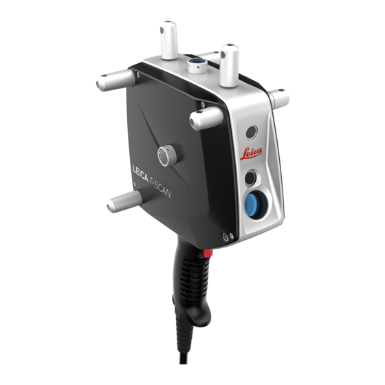
T‑Scan Components 2.4.1 T‑Scan Sensor Front view Aperture for laser beam (scan line) Aperture for pilot beam Aperture for receiver optics Trigger key 007444_001 Back view Status LED for T‑Scan controller Trigger key (front side) Marker LED Stand-off indicator LED Status LED for Laser Tracker Reflector... - Page 17 007509_001 T‑Scan indicators Acoustical status information To inform about the current measurement status of the sensor, the T‑Scan can give an acoustical status information. For example, the following status information is indicated by different acoustic signals: Laser Tracker beam locked on and ready to measure •...
- Page 18 LED Sta- Status information Maximum working distance, stand-off is at far end of work- ing range Mid working distance Minimum working distance, stand-off is at close end of work- ing range Status LED for The status LED for the Laser Tracker shows: Laser Tracker the communication status between T‑Scan sensor and Laser Tracker •...
-
Page 19: T-Scan Holder
Colour Pattern Status information Green Static Computer software has connected to T‑Scan controller. 2.4.2 T‑Scan holder Horizontal scanner Use the horizontal scanner holder (a) as a safe storage place for the T‑Scan holder sensor. 015904_001 Horizontal scanner holder 2.4.3 T‑Scan controller Control unit for The T‑Scan controller is the control unit for the T‑Scan sensor. -
Page 20: General Operating Principle
Back view Connector for scanner cable Fuse Power socket for: MPS21 or MPB25 Connector for trigger cable 007452_003 LAN connection to applica- Connector for trigger/probe tion computer cable MPS21, power supply unit LAN connection to Laser MPB25, external Li-Ion Tracker controller battery: 37 V and 8.1 Ah General Operating Principle Measurement... - Page 21 Optimal distance: Emerging laser beam Pilot beam Reflected beam Trigger key Stand-off indicator LED 007454_001 Distance too large: Emerging laser beam Pilot beam (above the scan line) Reflected beam Trigger key Stand-off indicator LED 007504_001 Description of the System...
- Page 22 6DOF system robot or machine to measure clouds of points. The T‑Scan works with the Leica Absolute Tracker 6DOF system. The measurement range of the T‑Scan depends on the Laser Tracker model that is used. The Absolute Tracker controller synchronises all relevant system components to a common time base.
- Page 23 Measurement Rotation around the X-axis – Omega w • Camera - parame- Rotation around the Y-axis – Phi j • ter for orientation Rotation around the Z-axis – Kappa k • Reflectors The reflectors are at the centre of each face of the T‑Scan. The reflectors are glass prisms which reflect the AIFM laser beam of the Laser Tracker to sup- port the initial distance measurement of the Absolute Distance Meter (ADM) and the tracking measurement of the Interferometer (IFM).
-
Page 24: Accessories
Refer to the brochure “Leica Laser Tracker Product Catalog” for detailed information on extra accessories. ☞ The use of accessories from third-party manufacturers without prior approval of Leica Geosystems is not permitted. Unauthorised modifications to the sys- tem make the warranty null and void. Accessories... -
Page 25: Operation
Operation Setup General The first installation of the product should be done by authorised Leica Geo- systems personnel. Installation by unauthorised personnel may cause damage and will make the warranty null and void. Cabling of T‑Scan The following illustration shows the correct cabling to connect the T‑Scan sys- system compo- tem components. - Page 26 ☞ For measurements that require utmost accuracy, a warm-up time of 30 minutes must be observed for the T‑Scan sensor before starting the measurement. Working with the Observe the following guidelines for the Laser Tracker: Laser Tracker • Set up the Laser Tracker in a way that the 6DOF position of the T‑Scan sensor can be captured from all required measurement positions.
- Page 27 007455_001 Unfavourable ori- If the T‑Scan sensor is used in an unfavourable orientation, some parts of the entations of the scan line could exceed the working range of the sensor. In this case, the T‑Scan sensor measurement data may not be captured completely. Example for unfavourable orientations of the T‑Scan sensor: Obstruction of the Certain shapes of the measuring object, for example edges, can cause an...
- Page 28 007457_001 Total reflection of Under certain circumstances, the surface of the measuring object (a) can the laser beam totally reflect the laser beam. This total reflection occurs when the angle of reflection is the same as the angle of incidence. In that case, too much light is returned to the receiver optics.
-
Page 29: Accuracy
To start data recording hold down the trigger key on the handle of the T‑Scan sensor. As long as the trigger key is held down, the data is recorded. ☞ Ensure that the stand-off is at the centre of the working range. Move the T‑Scan sensor perpendicularly to the scan direction. -
Page 30: Maximum Permissible Error (Mpe)
Typical measure- ment results of the Absolute Tracker are half of the relevant MPE values. 4.3.3 Measurement Uncertainty Specification of The following specification of uncertainty is achieved with the Leica T‑Scan uncertainty with under stable environmental conditions. T‑Scan Operation... - Page 31 ☞ Refer to "7 Technical Data" for detailed specifications of the product. Spatial length U L The measurement uncertainty of the spatial length “U L ” is defined as the deviation of a measured length from its nominal value. This deviation is specified as a function of the shortest distance between the Laser Tracker and the measured length.
-
Page 32: Check & Adjust
Check & Adjust Description Leica Geosystems products are manufactured, assembled and adjusted to the best possible quality. Quick temperature changes, frequent movements of the product, shock or stress can cause deviations and decrease the measure- ment accuracy. It is therefore recommended to check and adjust (compen- sate) the product from time to time. -
Page 33: Care And Transport
Shipping When transporting the product by rail, air or sea, always use the complete original Leica Geosystems packaging, container and cardboard box, or its equivalent, to protect against shock and vibration. Field adjustment Periodically carry out test measurements and perform the field adjustments indicated in the Tracker Pilot Reference Manual and T‑Scan Collect, par-... - Page 34 The following optical parts must be cleaned regularly: Reflector • • Infrared LEDs NOTICE Improper cleaning Improper cleaning can destroy optical surfaces which may lead to a malfunc- tion. Precautions: ▶ Cleaning of all optical parts requires great care. ▶ Only use appropriate cleaning material and follow the cleaning proce- dure described in this User Manual.
-
Page 35: Maintenance
Maintenance Service The product is a high-precision measuring instrument and to be handled with care. Maintenance of the equipment must be carried out by a Leica Geosys- tems authorised Service Centre. Service Intervals The periodicity of service intervals depends on the conditions of use. We rec-... -
Page 36: Technical Data
Technical Data Physical dimen- 209.4 mm sions 007461_001 T‑Scan Sensor Dimensions Size ca. 210 x 380 x 138 mm Weight (without cable) ca. 1.1 kg 235.5 mm 007462_001 T‑Scan Controller Dimensions Size 255.5 x 235.5 x 95.3 mm Weight 3.73 kg Electrical Power MPS21 AC/DC Adapter Value... - Page 37 MPS21 AC/DC Adapter Value Power 180 W Max. input AC current 1.7 A (115 V AC); 0.9 A (230 V AC) Max. input AC current (over current protec- tion) MPB25 External Li-Ion Battery Value Output Voltage 37 V DC Capacity 8.1 Ah Max.
- Page 38 Conformity to FCC Part 15 (applicable in US) • national regula- Hereby, Leica Geosystems AG, declares that the product/s tions is/are in compliance with the essential requirements and other relevant provisions of the applicable European Direc- tives. The declaration of conformity can be consulted at http://www.leica-geosystems.com/ce.
-
Page 39: Software Licence Agreement
Rights, Limitation of Liability, Exclusion of other Assurances, Governing Law and Place of Jurisdiction. Please make sure, that at any time you fully comply with the terms and conditions of the Leica Geosystems Software Licence Agreement. Such agreement is provided together with all products and can also be refer- red to and downloaded at the Leica Geosystems home page at http://leica-geosystems.com/about-us/compliance-standards/legal-docu-... -
Page 40: Appendix A Abbreviations
Appendix A Abbreviations Abbreviations The following abbreviations may be found in this manual: Term Description three-dimensional 6DOF 6 degrees of freedom Absolute Distance Meter AIFM Absolute Interferometer Absolute Tracker Electromagnetic Compatibility Standard of the European Committee for Standardization International Electrotechnical Commission Interferometer Light Emitting Diode Tracker Programming Interface... -
Page 41: Appendix B Regional Contact Addresses
Toll free +1 866 756 6763 Fax +1 937 247 0426 Phone +1 316 634 0856 Fax +1 316 634 0878 Refer to "Sales & Support Contacts" on www.leica-geosystems.com/metrol- ogy for a complete list of regional contacts. Regional Contact Addresses... - Page 42 820621-1.2.0en Original text Published in Switzerland © 2017 Leica Geosystems AG, Heerbrugg, Switzerland Leica Geosystems AG Heinrich-Wild-Strasse CH-9435 Heerbrugg Switzerland Phone +41 71 727 31 31 www.leica-geosystems.com...
Need help?
Do you have a question about the T-Scan 5 and is the answer not in the manual?
Questions and answers