Leica GPS1200 Series Manual
Hide thumbs
Also See for GPS1200 Series:
- Technical reference manual (1416 pages) ,
- Field manual (212 pages) ,
- User manual (153 pages)
Advertisement
Quick Links
Advertisement

Related Manuals for Leica GPS1200 Series


Summary of Contents for Leica GPS1200 Series
- Page 1 GPS1200 System Field Manual 1 Version 1.1 English...
- Page 2 The model and the serial number of your product are indicated on the type plate. tion Enter the model and serial number in your manual and always refer to this informa- tion when you need to contact your agency or Leica Geosystems authorized service workshop. Type: _____________________ Serial No.:...
- Page 3 Symbols The symbols used in this manual have the following meanings: Type Description Important paragraphs which must be adhered to in practice as they enable the product to be used in a technically correct and efficient manner. Trademarks • Windows (registered trademark of Microsoft Corporation) •...
-
Page 4: Table Of Contents
Table of Contents GPS1200 Table of Contents In this manual Chapter Page How to Use this Manual User Interface Equipment Setup Determining Antenna Heights Manage... - Getting Started Manage...\Jobs Manage...\Data Manage...\Codelists Coding Manage...\Coordinate Systems 10-1 Manage...\Configuration Sets 11-1... - Page 5 Manage...\Antennas 12-1 Convert...\Export Data from Job 13-1 Convert...\Import ASCII/GSI Data to Job 14-1 Index Table of Contents GPS1200...
-
Page 6: How To Use This Manual
How to Use this Manual GPS1200 1 How to Use this Manual It is recommended to set-up the instrument while reading through this manual. Path Main Menu: Manage...\Data stands for this working sequence: From the Main Menu select Manage... and then select Data. Screen CONFIGURE General Menu describes the name of the screen. - Page 7 Example 2: In REFLINE Define Reference, Reference page, <Task: XX Line> indicates that the explanation provided is valid for the options <Task: Measure to Line>, <Task: Stake to Line> and <Task: Gridstake Line>. Keys Two different types of keys can be found on the instrument. These are fixed keys and softkeys.
- Page 8 How to Use this Manual GPS1200 Throughout the manual, stepwise instructions are used. Keys to be pressed within these instructions are indicated as for example ENTER, CONT (F1) or SHIFT INDIV (F5). Index The index is at the back of the manual. Menu tree The menu tree helps finding a topic graphically.
- Page 9 • The RX1200 is available as RX1210 or RX1220 and with touch screen function- ality as RX1210T or RX1220T. The names RX1210 and RX1220 are used throughout the manual and may also represent the T models. Only use the supplied stylus on the touch screens of the T models. •...
- Page 10 How to Use this Manual GPS1200 Name of documentation Description GPS1200 Application Describes specific onboard application programs in Programs Field Manual standard use. Intended as a quick reference field guide. GPS1200 Technical Overall comprehensive guide to the system and Reference Manual program functions.
- Page 11 How to Use this Manual GPS1200...
-
Page 12: User Interface
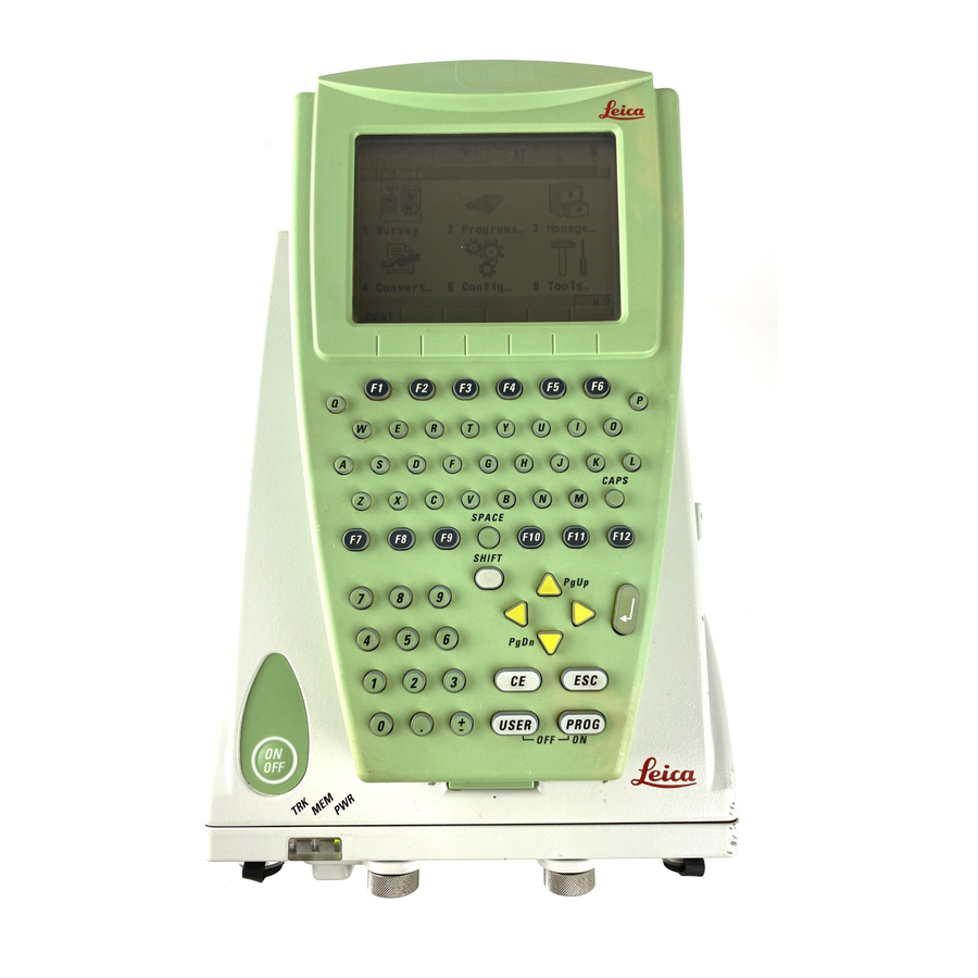
User Interface GPS1200 2 User Interface In this chapter Topic Page Keyboard Screen General Operating Principles Icons 2-13 Symbols 2-25... - Page 13 Keyboard Keyboard a) Function keys F1-F6 b) Alpha keys CAPS c) CAPS SPACE d) Hot keys F7-F12 SHIFT PgUp e) SPACE, SHIFT ENTER PgDn g) Arrow keys USER PROG h) CE, ESC, USER, PROG Numeric keys GPS12 010 User Interface GPS1200...
- Page 14 User Interface GPS1200 Keys Function Function keys F1- Correspond to the six softkeys that appear on the bottom of the screen when the screen is activated. Alpha keys To type letters. CAPS Switches between upper case to lower case letters. Hot keys F7-F12 User definable keys to execute chosen commands or access chosen screens.
- Page 15 Function Leaves the current menu or dialogue without storing any changes made. USER Calls the user defined menu. PROG (ON) • If the receiver is off: to turn the receiver on. • If the receiver is on: press at any time to access menu to select an application program.
- Page 16 User Interface GPS1200 Screen Screen a) Time b) Caption c) Title d) Screen area e) Message line Icons g) ESC h) SHIFT icon CAPS Softkeys GPS12 129 Elements of the Element Description screen Time The current local time is shown. Caption Shows location either in Main Menu, under PROG key or USER key.
- Page 17 Element Description Screen area The working area of the screen. Message line Messages are shown for 10 s. Icons Shows current status information of the instrument. Refer to "2.4 Icons". Can be used with touch screen. Can be used with touch screen. Same functionality as the fixed key ESC.
- Page 18 User Interface GPS1200 General Operating Principles Keyboard and The user interface is operated either by the keyboard or by the touch screen with touch screen supplied stylus. The workflow is the same for keyboard and touch screen. The difference is the way information is selected and entered.
- Page 19 Operation Description To accept data entered Tap somewhere else on the screen outside of the input into an input field and exit field. the edit mode Select from a menu Appearance Description To select an item from a menu, do one of the following: Move the focus to the item.
- Page 20 User Interface GPS1200 Appearance Description 3. ENTER or tap outside of the field. Edit an individual Appearance Description character in input A character can be inserted or overwritten. The proce- fields dure is the same for both cases. 1. Highlight the field. 2.
- Page 21 Step Description For the keyboard: ENTER. Toggle to the desired special character set by using the up/down arrow keys. Press the function key assigned to the required character group. Press the function key with the required character. Repeat step 4. and 5. for entering more special characters of the same character set.
- Page 22 User Interface GPS1200 2-11 ENTER or tap on the field to access the choicelist. Opening a choicelist reveals either a simple listbox or a comprehensive listbox dialogue. Simple listbox Appearance Description Selection • Choicelist shows • Highlight an item and items to select.
- Page 23 Listbox dialogue Appearance Description Selection • Choicelist fills the • Highlight an item and whole screen. CONT (F1) or tap an item. • A search field is shown. • To exit without changes press ESC or • A scroll bar is shown if tap .
- Page 24 User Interface GPS1200 2-13 Icons Description The icons provide information related to basic receiver functions. The icons that appear depend upon which GPS1200 receiver is used and the current receiver configuration. Allocation of icons b c d e f g h i a) Position status b) Number of visible satellites c) Contributing satellites...
- Page 25 Icon Description No icon No position available Autonomous solution available. Code solution available. Phase fixed solution available. The ticks indicate that an ambi- guity check is being made. Number of visible Displays the number of theoretically visible satellites above the configured cut off satellites angle according to the current almanac.
- Page 26 User Interface GPS1200 2-15 Icon Description The number of satellites being tracked. MaxTrack mode is active. The number of satellites being tracked. Receiver is configured to accept an external oscillator input. Contributing satel- Displays the number of satellites on L1 and L2 that are contributing to the currently lites computed position solution.
- Page 27 Icon Description The number of contributing satellites can differ from the number of visible satellites. This may be either because satellites cannot be viewed or the observa- tions to these satellites are considered to be too noisy to be used in the position solution. Real-time device Displays the real-time device configured to be used and its status.
- Page 28 User Interface GPS1200 2-17 Icon Description Digital cellular phone transmitting Radio transmitting RS232 transmitting Bluetooth enabled device attached and transmitting. A digital cellular phone is shown as an example. Real-time mode: Rover An arrow pointing down indicates a rover configuration. The arrow flashes when real- time messages are received.
- Page 29 Icon Description Digital cellular phone receiving Radio receiving RS232 receiving Bluetooth enabled device attached and receiving. A digital cellular phone is shown as an example. The Wide Area Augmentation System, European Geosta- tionary Navigation Overlay Service or MTSAT Satellite-based Augmentation System is being used. User Interface GPS1200 2-18...
- Page 30 User Interface GPS1200 2-19 Available for GRX1200 Pro Icon Description Ethernet device Position mode Displays the current position mode depending on the configuration defined. Symbols are added to the basic position mode icon when raw data logging or logging of auto points is configured. As soon as this icon becomes visible the receiver is in a stage where practical operation can commence.
- Page 31 Icon Position Point Raw data Logging of auto Move mode occupation logging points antenna Static Moving Moving Moving By time Moving By distance or height Yes Moving By stop & go User Interface GPS1200 2-20...
- Page 32 User Interface GPS1200 2-21 Quick coding The quick coding is displayed. Visible during Survey and other application programs where it is possible to measure a point with quick codes. Touch screen: Tapping the icon turns the quick coding on or off. Refer to "9.3 Quick Coding".
- Page 33 Icon Description Quick coding for quick codes with three digits is turned off. Line/area The number of lines and areas currently open in the active job is displayed. Touch screen: Tapping the icon leads to MANAGE Data: Job Name. Icon Description The number of lines and areas which are currently open in the active job is shown.
- Page 34 User Interface GPS1200 2-23 Icon Description The CompactFlash card is inserted and can be removed. The CompactFlash card is inserted and cannot be removed. It is strongly recommended not to remove the CompactFlash card to avoid loss of data. The internal memory is the active memory device. No icon The CompactFlash card is the active memory device.
- Page 35 Icon Description One internal battery in battery compartment A is in use. One internal battery in battery compartment B is in use. Two internal batteries, one in each battery compartment A and B. Black indicates the battery currently in use. External battery attached and in use.
- Page 36 User Interface GPS1200 2-25 Symbols Description The symbols provide information regarding settings. Filter Symbol Description Example The filter symbol is shown on the Point, Line, Area or Map page if a point, line or area filter is active. Attributes Symbol Description Example The attribute symbol is displayed in MANAGE...
- Page 37 Largest residual Symbol Description Example This symbol is used to indicate the largest residual in DET C SYS Step 4: Check Residuals. Staked out Symbol Description Example This symbol is used in MANAGE Data: Job Name to indicate points which have been staked out. Wake-Up Sessions Symbol Description...
-
Page 38: Equipment Setup
Equipment Setup GPS1200 3 Equipment Setup In this chapter Topic Page Receiver Ports Post-Processed Static Reference on Pillar Real-Time Reference, Single Tripod Real-Time Rover, Pole and Minipack 3-10 Real-Time Rover, All-on-Pole 3-14... - Page 39 Receiver Ports Description All receiver ports on the GPS1200 are located on the receiver front panel. Ports at the GX1210 GX1220 GX1230, GX1200 with PPS/Event option and GRX1200 receiver front panel E1 E2 GPS12_001a Equipment Setup GPS1200...
- Page 40 Equipment Setup GPS1200 a) Port E2: Event input 2, on GX1200 g) Port ANT: GPS antenna in with PPS/Event option b) Port E1: Event input 1, on GX1200 h) Battery compartment B, not for with PPS/Event option GRX1200 Pro c) Battery compartment A Port PPS: PPS output, on GX1200 with CompactFlash card compart- with PPS/Event option...
- Page 41 Equipment Port Radio in a System 500 housing, using a Port P1, port P2 or port P3 cable External power Port PWR Equipment Setup GPS1200...
- Page 42 Equipment Setup GPS1200 Post-Processed Static Reference on Pillar The equipment setup described below is to be used for static operations on fixed surveying pillars. Equipment setup GPS12_012...
- Page 43 a) GPS antenna Receiver GX1210/GX1220/GX1230 AX1201/AX1202/AT504 b) Carrier g) Two batteries c) Tribrach h) 2.8 m antenna cable d) Pillar plate if required CompactFlash card e) RX1210, if required Transport container Equipment Setup GPS1200...
- Page 44 Equipment Setup GPS1200 Real-Time Reference, Single Tripod The equipment setup described below is to be used for real-time reference stations with normal radio coverage. Raw observation data may also be collected for post- processing.
- Page 45 Equipment setup GPS12_016 a) Radio antenna RX1210, if required b) Radio antenna arm 15 cm long Receiver GX1210/GX1220/GX1230 Equipment Setup GPS1200...
- Page 46 Equipment Setup GPS1200 c) GPS antenna AX1201/AX1202 k) Radio in housing d) Height hook Transport container e) Carrier m) 1.2 m antenna cable to connect radio housing to radio antenna Tribrach n) Two batteries g) 1.2 m antenna cable to connect o) CompactFlash card receiver and GPS antenna h) Tripod...
- Page 47 Real-Time Rover, Pole and Minipack The equipment setup described below is to be used for a real-time rover during extended periods of use in the field. Raw observation data may also be collected for post-processing. Equipment Setup GPS1200 3-10...
- Page 48 Equipment Setup GPS1200 3-11 Equipment setup GPS12_018 a) GPS antenna AX1201/AX1202 1.8 m, 8 pin LEMO cable...
- Page 49 b) Upper half aluminium pole with screw k) Receiver GX1210/GX1220/GX1230 or stub c) Grip for pole Two batteries d) RX1210 m) CompactFlash card e) Holder for RX1210 on pole n) Radio antenna Lower half aluminium pole o) Radio antenna arm 3 cm long g) 1.2 m antenna cable p) 1.2 m antenna cable to connect radio housing and radio antenna...
- Page 50 Equipment Setup GPS1200 3-13 Position of cables in the minipack a) 1.6 m antenna cable b) 1.8 m, 8 pin LEMO cable c) 1.2 m antenna cable to connect radio housing and radio antenna GPS12_036...
- Page 51 Real-Time Rover, All-on-Pole The equipment setup described below is to be used for a real-time rover during short periods of use, especially where there are many obstacles such as fences. Equipment Setup GPS1200 3-14...
- Page 52 Equipment Setup GPS1200 3-15 Equipment setup GPS12_022 a) GPS antenna AX1201/AX1202 g) 1.2 m antenna cable b) Upper half aluminium pole with screwh) Lower half aluminium pole...
- Page 53 c) Grip for pole Radio antenna d) Holder for receiver together with Radio in housing RX1210 on pole e) RX1210 k) Two batteries Receiver GX1210/GX1220/GX1230 l) CompactFlash card Equipment Setup GPS1200 3-16...
-
Page 54: Determining Antenna Heights
Determining Antenna Heights GPS1200 4 Determining Antenna Heights Pillar setup a) Mechanical reference plane b) Vertical phase centre eccentricity for c) Vertical phase centre eccentricity for d) Vertical height reading An AX1201/AX1202 antenna is shown. Vertical offset = 0 GPS12_031... - Page 55 Carrier and adapter dimensions GPS12_037 GPS12_038 GRT144 carrier with GAD31 screw-to- GRT146 carrier. stub adapter. Determining Antenna Heights GPS1200...
- Page 56 GPS1200 Tripod setup a) Mechanical reference plane b) Vertical phase centre eccentricity for c) Vertical phase centre eccentricity for d) Vertical offset For Leica standard antenna plus accessories: 0.36 m e) Vertical height reading An AX1201/AX1202 antenna is shown. GPS12_032...
- Page 57 Mechanical reference plane b) Vertical phase centre eccentricity for c) Vertical phase centre eccentricity for d) Vertical height reading: • For Leica standard pole consisting of an upper and a lower half: 2.00 m. • For Leica standard pole consisting of an upper and a lower half with an additional 1.00 m pole section...
-
Page 58: Manage
Manage... - Getting Started GPS1200 5 Manage... - Getting Started Accessing Step Description MANAGE XX step- Select Main Menu: Manage..by-step GPS1200 Management Select an option in the menu. CONT (F1) to access MANAGE XX. MANAGE XX can directly be accessed from a choicelist in some screens for example the begin screen of application programs. - Page 59 page indicate the number of open lines/areas. Example: Lines (2)/Areas (2) means that two lines are open. CONT (F1) To select an option and to return to the previous screen. For MANAGE Codelists, the codes from the high- lighted codelist are copied to the active job.
- Page 60 Manage... - Getting Started GPS1200 DEL (F4) To delete the option. Available unless MANAGE Data: Job Name, Lines (X) page and MANAGE Data: Job Name, Areas (X) page. USE (F4) To change between the options in the Open column for the highlighted line/area.
- Page 61 CFCRD (F6) or INTL (F6) Available for MANAGE Jobs. Avail- able for receivers with internal memory. To change between viewing jobs stored on the CompactFlash card or internal memory. SHIFT LOG (F4) Available for MANAGE Data: Job Name, Points page. To view points, lines, areas and free codes stored with the job sorted by time.
- Page 62 Manage... - Getting Started GPS1200 SHIFT SET-D (F4) Available for MANAGE Coordinate Systems and MANAGE Configura- tion Sets. Available unless a default coordinate system/configuration set is highlighted. To turn the highlighted coordinate system/configuration set into a user defined default coordinate system/configuration set stored in the receiver.
- Page 63 Next step IF an option THEN is to be selected highlight the desired option. CONT (F1) closes the screen and returns to the screen from where MANAGE XX was accessed. is to be created or highlight the option and NEW (F2)/EDIT (F3). Refer to the edited individual chapters.
- Page 64 Manage...\Jobs GPS1200 6 Manage...\Jobs In this chapter Topic Page Overview Creating a New Job/Editing a Job...
- Page 65 Overview Description Jobs • structure surveying projects. • contain all points, lines, areas and codes that are recorded and stored. • can be downloaded to LGO for post-processing or for data transfer to a further program. • can be uploaded from LGO, for example, for real-time stake out operations. •...
- Page 66 Manage...\Jobs GPS1200 Creating a New Job/Editing a Job Access step-by- Step Description step Refer to "5 Manage... - Getting Started" to access MANAGE Jobs (Device). In MANAGE Jobs (Device) highlight a job. When creating a new job, the settings of this job are applied to the new job, the codelist must be selected.
- Page 67 MANAGE XX Job, STORE (F1) General page To store the settings and to return to MANAGE Jobs (Device). DATA (F5) Available for editing a job. To view, edit and delete points, lines and areas stored with the job. Points, lines and areas are shown on sepa- rate pages.
- Page 68 Manage...\Jobs GPS1200 Description of fields Field Option Description <Name:> User input A unique name for the new job. The name may be up to 16 characters long and may include spaces. Input required. <Descrip- User input Two lines for a detailed description of the job. tion:>...
- Page 69 MANAGE IMPRT (F2) XX Job, Available for editing a job. To add Codelist page additional codes from a new codelist to the job. The name of this codelist is copied to the job. CODES (F4) Available for editing a job. To view, edit, delete, sort and group codes currently stored in the job.
- Page 70 Manage...\Jobs GPS1200 Field Option Description Output Available for editing a job if codes are stored in the job. If codes had been copied from a System RAM codelist, then the name of the codelist is displayed. If codes have not been copied from a System RAM codelist but typed in manually, then the name of the active job is displayed.
- Page 71 MANAGE In order to check measurements, the same point can be measured more than once. XX Job, If activated, an average or an absolute difference is calculated. Refer to paragraph Avge page "MANAGE XX Job, General page" for information on the softkeys. Description of fields Field Option...
- Page 72 Manage...\Jobs GPS1200 Field Option Description <Avge Limit User input Available for <Averaging Mode: Average>. Pos:> and The acceptable difference for the position and <Avge Limit height components. Ht:> From User input Available for <Averaging Mode: Absolute <Easting:> to Diffs>. The acceptable absolute differences for <Cartesian each coordinate component.
- Page 73 Manage...\Jobs GPS1200 6-10...
- Page 74 Manage...\Data GPS1200 7 Manage...\Data In this chapter Topic Page Overview Point Management Line/Area Management 7-18 Point Sorting and Filters 7-26...
- Page 75 Overview Description Data is a generic term for points, lines and areas. Data management is the administration of data stored in the active job. This includes • viewing data with their related information. • editing data. • creating new data. •...
- Page 76 Manage...\Data GPS1200 Point Management In this chapter Topic Page 7.2.1 Creating a New Point/Editing a Point 7.2.2 Mean Page 7-12...
- Page 77 7.2.1 Creating a New Point/Editing a Point Access step-by- Step Description step Refer to "5 Manage... - Getting Started" to access MANAGE Data: Job Name, Points page. MANAGE Data: Job Name, Points page If a point is to be edited, then highlight the point. NEW (F2)/EDIT (F3) to access MANAGE New Point/MANAGE Edit Point: Point ID.
- Page 78 Manage...\Data GPS1200 MANAGE XX Point, Coords page STORE (F1) To store the point and all associated information and to return to MANAGE Data: Job Name, Points page. COORD (F2) To view other coordinate types. NORTH (F3) or SOUTH (F3) Available for local geodetic or WGS 1984 geodetic coordinates when <Local Lat:>...
- Page 79 SHIFT ELL H (F2) or SHIFT ORTH (F2) Available for local coordinates. To change between the ellipsoidal and the orthometric height. SHIFT INDIV (F5) or SHIFT RUN (F5) To change between entering an indi- vidual point ID different to the defined ID template and the running point ID according to the ID template.
- Page 80 Manage...\Data GPS1200 Field Option Description If editing a point, then changing the point ID for a point of any class applies this new point ID to all other points with the same original name, regardless of class. Output Points of <Class: REF> cannot be renamed. Coordinates User input Negative geodetic coordinates are interpreted...
- Page 81 The name of the real-time reference station from where the GPS point was meas- ured, the name of antenna used to measure the point and the baseline values are shown in output fields. Next step PAGE (F6) changes to the next page. Refer to the relevant paragraph below. MANAGE The setting for <Thematc Codes:>...
- Page 82 Manage...\Data GPS1200 NAME (F3) or VALUE (F3) Available for attributes for which an attribute name can be typed in. To highlight <Attribute n:> or the field for the attribute value. The name of <Attribute n:> can be edited and an attribute value can be typed in. LAST (F4) To recall the last used attribute values which were stored with this...
- Page 83 Description of fields Field Option Description <Point Choicelist Available for <Thematc Codes: With Code:> Codelist>. All point codes of the job codelist can be selected. The description of the code is shown as an output field. The attributes are shown as output, input or choicelist fields depending on their definition.
- Page 84 Manage...\Data GPS1200 7-11 Next step THEN creating a point STORE (F1) stores the point and all associated information and returns to MANAGE Data: Job Name, Points page. editing a point • PAGE (F6) changes to the Annots page, if available. •...
- Page 85 7.2.2 Mean Page Description Various measured coordinate triplets for one point can be recorded using the same point ID. If the averaging mode is activated, an average is calculated. It is checked if the deviations of each single point are within the configured limits. After averaging, the Mean page becomes available in MANAGE Edit Point: Point ID and accessible from the Survey application program SURVEY Survey: Job Name, Survey page.
- Page 86 Manage...\Data GPS1200 7-13 Averaging Description mode Absolute The same as for Average above applies for Absolute Diffs. Diffs Additionally, the absolute difference between two points selected from a list of measured points, which are all stored with the same point ID, are computed. Averaging functionality is turned off.
- Page 87 STORE (F1) To store the changes and to return to the screen from where this screen was accessed. USE (F2) To include or exclude the highlighted coordinate triplet in or from the calcu- lation of the average. EDIT (F3) To view and edit the highlighted measured coordinate triplet.
- Page 88 Manage...\Data GPS1200 7-15 SHIFT DIFFS (F5) Available for <Averaging Mode: Absolute Diffs> and Yes set in the Use column for exactly two measure- ments. To display the absolute coor- dinate differences when a local coor- dinate system is active. Differences exceeding the defined limit are indi- cated by .
- Page 89 Column Description • The coordinate triplet is never included in the averaging computation. • ----- The coordinate triplet cannot be included in the averaging computation. Automatically set by the system. USE (F2) changes between the options. dPos The horizontal distance from the measured coordinate triplet to the average.
- Page 90 Manage...\Data GPS1200 7-17 Next step IF a measured THEN coordinate triplet is not to be viewed STORE (F1) stores the changes and returns to MANAGE Data: Job Name. is to be viewed highlight a measured coordinate triplet and EDIT (F3). Codes cannot be changed.
- Page 91 Line/Area Management In this chapter Topic Page 7.3.1 Overview 7-19 7.3.2 Creating a New Line/Area/Editing a Line/Area 7-20 Manage...\Data GPS1200 7-18...
- Page 92 Manage...\Data GPS1200 7-19 7.3.1 Overview Description A line/area consists of points and can be created/edited in MANAGE Data: Job Name. The individual points are measured within any application program. These can be all points except auxiliary points. Points can be simultaneously assigned to one or more lines and/or areas.
- Page 93 7.3.2 Creating a New Line/Area/Editing a Line/Area Creating/editing lines/areas and the functionality of all screens and fields are similar for lines/areas. For simplicity, only the creation/editing of a line is explained in this chapter. Access step-by- Step Description step Refer to "5 Manage... - Getting Started" to access MANAGE Data: Job Name.
- Page 94 Manage...\Data GPS1200 7-21 MANAGE XX Line, STORE (F1) General page To store the line and all associated information and to return to MANAGE Data: Job Name, Lines (X) page. Any existing lines and areas which are open are closed. MORE (F5) Available on MANAGE Edit Line: Line ID.
- Page 95 Field Option Description <Pts to All Points, Only The type of points which are used to form the Store:> Msd Pts, Only line during a survey. Auto Pts, Only Offset1 Pts or Only Offset2 Pts <Line Style:> Choicelist Available on MANAGE New Line. This is the line style in which lines/areas are represented in MapView and LGO.
- Page 96 Manage...\Data GPS1200 7-23 Field Option Description <Start Output Available on MANAGE Edit Line: Line ID. The Time:> and time/date when the line was created. <Start Date:> <End Time:> Output Available on MANAGE Edit Line: Line ID after and <End pressing MORE (F5). The time/date when the Date:>...
- Page 97 MANAGE All points belonging to the line are listed. The point that was added last to the line is Edit Line: Line ID, at the top of the list. Points page ADD (F2) To add an existing point from the active job to the line.
- Page 98 Manage...\Data GPS1200 7-25 MANAGE The functionality is very similar to MANAGE New Point, Code page. Refer to "7.2.1 XX Line, Creating a New Point/Editing a Point". Code page Next step STORE (F1) stores the changes and returns to MANAGE Data: Job Name, Lines (X) page.
- Page 99 Point Sorting and Filters In this chapter Topic Page 7.4.1 Sorting and Filters for Points, Lines and Areas 7-27 7.4.2 Point, Line and Area Code Filter 7-31 Manage...\Data GPS1200 7-26...
- Page 100 Manage...\Data GPS1200 7-27 7.4.1 Sorting and Filters for Points, Lines and Areas Description The sort settings define the order of the objects in the active job. The filter settings define the objects to be viewed. An active filter for an object is indicated in MANAGE Data: Job Name by on the right hand side of the page name.
- Page 101 MANAGE The available fields on this screen depend on the selected setting for <Filter:>. Sorts & Filters, Points page CONT (F1) To close the screen and to return to the screen from where this screen was accessed. STAKE (F5) To filter points for the Stakeout appli- cation program.
- Page 102 Manage...\Data GPS1200 7-29 Field Option Description <Filter:> Always available. The method the points are filtered by. No Filter Shows all points. Highest Class Shows points of highest class. Range of Pt ID's Shows points with point ID’s between the entered start and end ID. The points are left aligned and sorted by the first digit.
- Page 103 Field Option Description Point Code Shows points with selected codes attached. Radius From Pt Shows points within the defined radius from a particular point. The radius is the horizontal distance. Individual Line Shows points forming a selected line. This may for example be useful during stakeout.
- Page 104 Manage...\Data GPS1200 7-31 7.4.2 Point, Line and Area Code Filter For each object, a code filter exists. The point, line and area code filters are inde- pendent from each other. The functionality is identical. For simplicity, only the point code filter is explained. Access step-by- Step Description...
- Page 105 CONT (F1) To close the screen and return to the screen from where this screen was accessed. GROUP (F4) To activate and deactivate code groups. Codes belonging to a deacti- vated code group are not displayed in MANAGE Code Filter. USE (F5) To activate and deactivate the filter for the highlighted code.
- Page 106 Manage...\Codelists GPS1200 8 Manage...\Codelists In this chapter Topic Page Creating a New Codelist/Editing a Codelist Creating a New Code/Editing a Code...
- Page 107 Creating a New Codelist/Editing a Codelist It is recommended to create a codelist in LGO. A codelist can be transferred from LGO to the System RAM of the receiver using the CompactFlash card. Access step-by- Step Description step Refer to "5 Manage... - Getting Started" to access MANAGE Codelists. NEW (F2)/EDIT (F3) to access MANAGE New Codelist/MANAGE Edit Codelist.
- Page 108 Manage...\Codelists GPS1200 MANAGE XX Codelist STORE (F1) To store the codelist and to return to MANAGE Codelists. CODES (F4) To access MANAGE Codes where codes can be created, edited or deleted and code groups can be accessed. Description of fields Field Option Description...
- Page 109 Field Option Description <Creator:> User input The person’s name who is creating the new codelist. Input optional. Next step STORE (F1) stores the codelist and returns to MANAGE Codelists. Manage...\Codelists GPS1200...
- Page 110 Manage...\Codelists GPS1200 Creating a New Code Editing a Code Access step-by- Step Description step Refer to "5 Manage... - Getting Started" to access MANAGE Codelists. In MANAGE Codelists highlight the codelist of which codes are to be managed. EDIT (F3) to access MANAGE Edit Codelist. CODES (F4) to access MANAGE Codes.
- Page 111 Step Description If a code is to be edited, then highlight the code. NEW (F2)/EDIT (F3) to access MANAGE New Code/MANAGE Edit Code. Editing codes is similar to creating a new code. For simplicity, the screens are called MANAGE XX Code and differences are clearly outlined. MANAGE XX Code STORE (F1)
- Page 112 Manage...\Codelists GPS1200 NEW-A (F2) To add a new input field for an attribute of attribute type normal and of value type text. Attributes of attribute type mandatory or fixed and of value type real or integer must be created in LGO. Up to twenty attributes can be created.
- Page 113 Description of fields Field Option Description <Code:> User input A unique name for the new code. The name may be up to 16 characters long and may include spaces. Input required. <Code User input A detailed description of the code. This can be Desc:>...
- Page 114 Manage...\Codelists GPS1200 Field Option Description <Line Style:> Choicelist Available for <Code Type: Line> or <Code Type: Area>. The style in which lines/areas using this case are represented in MapView and LGO. Next step STORE (F1) adds the code to the codelist/stores the changes and returns to MANAGE Codelists.
- Page 115 Manage...\Codelists GPS1200 8-10...
- Page 116 Coding GPS1200 9 Coding In this chapter Topic Page Thematical Coding Free Coding 9-10 Quick Coding 9-16 Code and Attribute Mismatch 9-19...
- Page 117 Thematical Coding In this chapter Topic Page 9.1.1 Thematical Coding with Codelist 9.1.2 Thematical Coding without Codelist Coding GPS1200...
- Page 118 Coding GPS1200 9.1.1 Thematical Coding with Codelist Thematical coding of points with a codelist is explained in this chapter. Requirements • The job codelist contains thematical codes. • <Thematc Codes: With Codelist> in CONFIGURE Coding Settings. • A display mask with an input field for point codes must be configured. Access Open the choicelist for <Point Code:>...
- Page 119 CONT (F1) To return to the screen from where this screen was accessed. NEW (F2) To create a new code. ATRIB (F3) To type in attribute values for the selected code and/or add new attributes for the selected code. LAST (F4) Available if a point code has been previously used in the active job.
- Page 120 Coding GPS1200 MORE (F5) To display information about the code description, the code group and the quick code if codes with quick codes exist in the job. SHIFT GROUP (F4) To view, create, delete, activate and deactivate code groups. SHIFT SORT (F5) To sort codes by code name, code description, quick code or the last used.
- Page 121 • normal can be typed in. • fixed cannot be edited. CONT (F1) To return to the screen from where XX Select Point Code was accessed. The point code and any associated attribute values are stored when the point is stored. NEW-A (F2) To add a new attribute of type normal and of value type text.
- Page 122 Coding GPS1200 NAME (F3) or VALUE (F3) Available for attributes for which an attribute name can be typed in. To highlight <Attribute n:> or the field for the attribute value. LAST (F4) To recall the last used attribute values for the selected code. DEFLT (F5) To recall the default attribute values for the selected code.
- Page 123 9.1.2 Thematical Coding without Codelist Thematical coding without codelist for points is explained in this chapter. Requirements • <Thematc Codes: Without Codelist> in CONFIGURE Coding Settings. • A display mask with an input field for point codes must be configured. Thematical coding in the Survey application program is explained.
- Page 124 Coding GPS1200 OCUPY (F1) To start the point occupation.
- Page 125 Free Coding In this chapter Topic Page 9.2.1 Free Coding Using a Codelist 9-11 9.2.2 Free Coding with Direct Input 9-14 Coding GPS1200 9-10...
- Page 126 Coding GPS1200 9-11 9.2.1 Free Coding Using a Codelist In this chapter, free coding using a codelist is explained for points. Requirements • The job codelist contains free codes. • A hot key is configured to access the screen FREECODING Select Free Code or the user defined menu is configured to display the option Select Free Code.
- Page 127 STORE (F1) To store the free code and any asso- ciated attribute values and to return to the screen from where this screen was accessed. Next step Step Description Highlight the desired code. ATRIB (F3) FREECODING If configured for the selected code, input fields for attribute values are available. Enter Attributes Type in the attribute values.
- Page 128 Coding GPS1200 9-13 • fixed cannot be edited. The majority of the softkeys is identical to those available for thematical coding with codelist. Refer to "9.1.1 Thematical Coding with Codelist" for information on the iden- tical softkeys. STORE (F1) To return to the screen from where FREECODING Select Free Code was accessed and to store the free code, any associated attribute values...
- Page 129 9.2.2 Free Coding with Direct Input In this chapter, free coding with direct input is explained for points. Requirements A hot key is configured to access the screen FREECODING Enter Free Code & Attributes or the user defined menu is configured to display the option Enter Free Code.
- Page 130 Coding GPS1200 9-15 STORE (F1) To store the free code and any asso- ciated attribute values and to return to the screen from where this screen was accessed. LAST (F4) Available if a free code has been previously used in the active job. Accesses FREECODING Last Used Free Codes.
- Page 131 Quick Coding Requirements • The job codelist contains quick codes. • According to the requirements of the used CAD package, set <Rec Free Code: Before Point> or <Rec Free Code: After Point> in CONFIGURE Coding Settings. Activate quick The current setting for <Quick Code:> in CONFIGURE Coding Settings deter- coding mines how quick coding is activated.
- Page 132 Coding GPS1200 9-17 Access CONFIGURE Coding Settings and change the setting manually. • For <Quick Code: Never> in CONFIGURE Coding Settings Access CONFIGURE Coding Settings and change the setting manually. Quick coding step- Step Description by-step Refer to paragraph "Activate quick coding" to activate quick coding. A screen must be active where points can be occupied.
- Page 133 Step Description • For free codes: The free code, associated attribute values and time related information are stored. The setting for <Rec Free Code:> in CONFIGURE Coding Settings determines if the free code is stored before or after the point. Attribute values for attributes of type •...
- Page 134 Coding GPS1200 9-19 Code and Attribute Mismatch Code/attribute mismatch for points is explained in this chapter. Code/attribute mismatch for lines and areas is identical to code/attribute mismatch for points. For simplicity, the word point is used. Description If a point with the same point ID exists in the job, the codes, the attribute names and the attribute values of the new and the existing point must be identical.
- Page 135 MORE (F5) To display information about the code description, the code group and any attributes associated with the high- lighted code. The name of the screen changes with pressing CURNT (F5) or STORD (F5): Attributes Already Stored Pressing CURNT (F5): XX Attributes Being Stored The code and attributes of the new point are displayed.
- Page 136 Manage...\Coordinate Systems GPS1200 10-1 10 Manage...\Coordinate Systems In this chapter Topic Page 10.1 Overview 10-2 10.2 Creating a New Coordinate System/Editing a Coordinate System 10-3 10.3 Transformations/Ellipsoids/Projections 10-6 10.4 Geoid/CSCS Models 10-12...
- Page 137 10.1 Overview Description A coordinate system • consists of up to five elements. • allows the conversion from WGS 1984 geodetic or cartesian coordinates to local cartesian, geodetic or grid coordinates and back. Elements of coordi- The five elements which define a coordinate system are: nate system •...
- Page 138 Manage...\Coordinate Systems GPS1200 10-3 10.2 Creating a New Coordinate System/Editing a Coordinate System Access step-by- Step Description step Refer to "5 Manage... - Getting Started" to access MANAGE Coordinate Systems. In MANAGE Coordinate Systems highlight a coordinate system. When creating a new coordinate system, a copy of this coordinate system is taken for further configurations.
- Page 139 Description of fields Field Option Description <Name:> User input A unique name for the coordinate system. The name may be up to 16 characters long and may include spaces. <Residuals:> Available for transformations with control points. The method by which residuals are distributed throughout the transformation area.
- Page 140 Manage...\Coordinate Systems GPS1200 10-5 Field Option Description <Pre Trans- Output Available for editing Twostep transformations. form:> The name of a preliminary 3D transformation which is used together with the selected projec- tion to obtain preliminary grid coordinates to be used for a final 2D transformation. <Ellipsoid:>...
- Page 141 10.3 Transformations/Ellipsoids/Projections In this chapter Topic Page 10.3.1 Accessing Transformation/Ellipsoid/Projection Management 10-7 10.3.2 Creating/Editing a Transformation/Ellipsoid/Projection 10-9 Manage...\Coordinate Systems GPS1200 10-6...
- Page 142 Manage...\Coordinate Systems GPS1200 10-7 10.3.1 Accessing Transformation/Ellipsoid/Projection Management Access step-by- Step Description step Refer to "5 Manage... - Getting Started" to access MANAGE Coordinate Systems. In MANAGE Coordinate Systems highlight a coordinate system to be edited. EDIT (F3) In MANAGE Edit Coordinate System highlight <Transform:>, <Ellip- soid:>...
- Page 143 Next step THEN a transforma- highlight the desired transformation/ellipsoid/projection. tion/ellip- CONT (F1) closes the screen and returns to the screen from soid/projection is to where MANAGE XX was accessed. be selected a transformation/an highlight the transformation/ellipsoid/projection and NEW ellipsoid/projection (F2)/EDIT (F3). Refer to "10.3.2 Creating/Editing a Transfor- is to be created or mation/Ellipsoid/Projection".
- Page 144 Manage...\Coordinate Systems GPS1200 10-9 10.3.2 Creating/Editing a Transformation/Ellipsoid/Projection Creating/editing an ellipsoid/projection is very similar to creating/editing a transfor- mation which is explained below. The main difference is that MANAGE XX Ellipsoid and MANAGE XX Projection do not use pages and all the information is input on one screen.
- Page 145 MANAGE Description of fields XX Transformation, Field Option Description General page <Name:> User input A unique name for the transformation. The name may be up to 16 characters long and may include spaces. <Type:> Output No other transformations than Classic 3D can be created.
- Page 146 Manage...\Coordinate Systems GPS1200 10-11 MANAGE Description of fields XX Transformation, Field Option Description More page <Height Choicelist or The type of heights to be computed. When Mode:> Output editing a transformation, the option cannot be changed. <Transf Choicelist The transformation model to be used. For Model:>...
- Page 147 10.4 Geoid/CSCS Models The creation of CSCS models on the receiver and the functionality of all screens and fields is similar to those for geoid models. For simplicity, geoid models are used as an example in this chapter. Access step-by- Step Description step...
- Page 148 Manage...\Coordinate Systems GPS1200 10-13 CONT (F1) To select the highlighted geoid model and to return to the previous screen. CFCRD (F2) To create a new geoid model. For each geoid field file on the Compact- Flash card, one geoid model is auto- matically created.
- Page 149 MORE (F5) To display information about the geoid field file used and the device on which the geoid field file is stored. Manage...\Coordinate Systems GPS1200 10-14...
- Page 150 Manage...\Configuration Sets GPS1200 11-1 11 Manage...\Configuration Sets In this chapter Topic Page 11.1 Overview 11-2 11.2 Creating a New Configuration Set 11-3 11.3 Editing a Configuration Set 11-5...
- Page 151 11.1 Overview Description The receiver has numerous user configurable parameters and functions. This allows a variety of preferences to be addressed. The configuration of the parameters and functions for an individual measuring technique are combined in a configuration set. Default configura- Default configuration sets exist on the instrument.
- Page 152 Manage...\Configuration Sets GPS1200 11-3 11.2 Creating a New Configuration Set Access step-by- Step Description step Refer to "5 Manage... - Getting Started" to access MANAGE Configura- tion Sets. In MANAGE Configuration Sets highlight a configuration set. A copy of this configuration set is taken for further configurations. NEW (F2) to access MANAGE New Configuration Set.
- Page 153 Next step STORE (F1) accesses the next subsequent screen in the configuration wizard. Refer to the chapters "Config...\XX" for information on the screens. Manage...\Configuration Sets GPS1200 11-4...
- Page 154 Manage...\Configuration Sets GPS1200 11-5 11.3 Editing a Configuration Set Access step-by- Step Description step with using Refer to "5 Manage... - Getting Started" to access MANAGE Configura- configuration set tion Sets. wizard In MANAGE Configuration Sets highlight a configuration set to be edited.
- Page 155 Manage...\Configuration Sets GPS1200 11-6...
- Page 156 Manage...\Antennas GPS1200 12-1 12 Manage...\Antennas In this chapter Topic Page 12.1 Overview 12-2 12.2 Creating a New Antenna/Editing an Antenna 12-3...
- Page 157 12.1 Overview Description • Leica Geosystems antennas are predefined as default and can be selected from a list. • Additional antennas can be defined. • Default antennas contain an elevation dependent correction model. • New antenna correction models can be set up and transferred to the receiver using LGO.
- Page 158 NEW (F2)/EDIT (F3) to access MANAGE New Antenna/MANAGE Edit Antenna. Editing antennas is similar to creating a new antenna. All fields can be edited except those of Leica default antennas. For simplicity, the screens are called MANAGE XX Antenna.
- Page 159 MANAGE XX Antenna, General page STORE (F1) To store the new antenna and to return to MANAGE Antennas. Description of fields Field Option Description <Name:> User input A unique name for the new antenna. <Hz Offset:> User input Horizontal offset of measurement reference point.
- Page 160 Manage...\Antennas GPS1200 12-5 Field Option Description <L2 User input Offset of L2 phase centre. PhOffset:> <Copy Addi- Yes or No Allows additional corrections to be copied from tional the antenna which was highlighted when Correc- MANAGE New Antenna was accessed. tions:>...
- Page 161 Field Option Description <Set Up User input The set up number of the antenna. This identi- Number:> fies the version number of the current calibra- tion. Next step STORE (F1) stores the antenna and returns to MANAGE Antennas. Manage...\Antennas GPS1200 12-6...
- Page 162 Convert...\Export Data from Job GPS1200 13-1 13 Convert...\Export Data from Job In this chapter Topic Page 13.1 Overview 13-2 13.2 Exporting Data 13-3...
- Page 163 • to a file on the internal memory, if fitted. • via RS232 to a Leica TPS400/700 instrument. Export format The export format must be composed individually as format file using LGO. Refer to the online help of LGO for information on creating format files.
- Page 164 Convert...\Export Data from Job GPS1200 13-3 13.2 Exporting Data Requirements At least one format file was created using LGO and has been transferred to the System RAM. Access Select Main Menu: Convert...\Export Data from Job. EXPORT Export Data from CONT (F1) To export the data.
- Page 165 CSYS (F6) To update the coordinate system in which the coordinates are exported. Description of fields Field Option Description <Export To:> CF Card, Defines to where the exported file should be Internal written. Memory, if fitted, or RS232 <Directory:> Data or GSI Available for <Export To: CF Card>.
- Page 166 Convert...\Export Data from Job GPS1200 13-5 Field Option Description <Coord Output The coordinate system currently attached to the System:> selected <Job:>. <Format Choicelist The format files currently available in the File:> System RAM. <File Name:> User input Available for <Export To: CF Card> and <Export To: Internal Memory>.
- Page 167 Convert...\Export Data from Job GPS1200 13-6...
- Page 168 Convert...\Import ASCII/GSI Data to GPS1200 14-1 14 Convert...\Import ASCII/GSI Data to Job In this chapter Topic Page 14.1 Overview 14-2 14.2 Importing Data 14-3...
- Page 169 14.1 Overview Description The settings on this screen define the data that can be imported. The data to import must be stored on the CompactFlash card. Data can be imported to a job • on the CompactFlash card. • on the internal memory, if fitted. Import formats Data can be imported in ASCII, GSI8 or GSI16 format.
- Page 170 Convert...\Import ASCII/GSI Data to GPS1200 14-3 14.2 Importing Data Requirements • For ASCII files: At least one ASCII file with any file extension is stored in the \DATA directory of the CompactFlash card. • For GSI files: At least one ASCII file in GSI format with the file extension *.gsi is stored in the \GSI directory of the CompactFlash card.
- Page 171 CONF (F2) For <Import: ASCII Data>: To select the delimiter, the positions of the particular variables and, if required, the number of lines used to describe each point or if the variables are delimited by one or multi spaces. For <Import: GSI Data>: Coordi- nates can be switched for “left handed”...
- Page 172 Convert...\Import ASCII/GSI Data to GPS1200 14-5 Description of fields Field Option Description <Import:> Choicelist The type of data to be imported. <From File:> Choicelist For <Import: ASCII Data> all files in the \DATA directory on the CompactFlash card can be selected.
- Page 173 Convert...\Import ASCII/GSI Data to GPS1200 14-6...
- Page 174 Index GPS1200 Index Antennas Default ............12-2 Absolute coordinate difference Reset default settings ........5-5 Display ............7-15 Area ..............2-13 Limit exceeded ..........7-15 Close ............. 5-3 Absolute difference between two points ...7-13 Create ............7-20 Access, MANAGE XX ........5-1 Edit .............. 7-20 Activate Icon .............
- Page 175 ASCII ..............14-2 CE ..............2-3 Attribute Choicelist ............2-10 Add for Close Free code ..........9-12 Area .............. 5-3 Thematical code ........9-4 Line ............... 5-3 Type in new ...........8-7 Code Attribute mismatch ..........9-19 Create ............8-5 Attributes, symbol ..........2-25 Edit ..............8-5 Average ............7-12 Code filter for lines and areas ......
- Page 176 Index GPS1200 Coding Connect equipment and ports ......3-3 Free Coordinate system ........... 10-1 Direct input ..........9-14 Create ............10-3 Using codelist .........9-11 Edit .............. 10-3 Quick ............9-16 Turn into user defined default ....... 5-5 Thematical Coordinate systems With codelist ..........9-3 Recall deleted default ........
- Page 177 Projection ............10-9 Delete Transformation ..........10-9 Area .............. 5-4 CSCS model ...........10-12 Code group ........... 8-5 Create from CompactFlash card ....10-13 Coordinate triplet ........7-14 Geoid/CSCS model ........10-13 Line ............... 5-4 Data ..............7-2 Option in MANAGE ........5-3 Export ............13-1 Point from line ..........
- Page 178 Index GPS1200 Ellipsoids ............10-6 End date ............7-23 Edit End time ............7-23 Antenna ............12-3 ENTER ............... 2-3 Area .............7-20 Equipment setup ..........3-1 Code ..............8-5 ESC ..............2-4 Codelist ............8-2 Exceeded limit Configuration set .........11-5 Absolute coordinate difference ....7-15 Coordinate system ........10-3 Average ............
- Page 179 Coding ............9-5 GSI16 ............... 14-2 Fields ..............1-1 GSI8 ..............14-2 FILT ..............5-5 Export ............13-3 Filter Height mode ........... 10-11 Activate/deactivate for codes ......7-32 Height, pole ............4-4 Point, line and area codes ......7-31 Points in Stakeout application program ..7-28 Points, lines and areas ........7-27 Icons ..............
- Page 180 Index GPS1200 Internal memory ..........2-13 Icon .............2-22 Left, arrow key ..........2-10 INTL ..............5-4 Length .............. 7-22 Download, jobs ..........6-2 Job ..............6-1 Upload, jobs ..........6-2 Create ............6-3 Limit, exceeded Edit ..............6-3 Absolute coordinate difference ....7-15 Average ............7-16 Symbol ............
- Page 181 Lines Manual Sorting and filters ........7-27 GPS1200 LOG ..............6-4 Application Programs Field ...... 1-5 Logged data, view ..........5-4 Technical Reference ........ 1-5 User ............1-4 How to Use This ........... 1-1 MANAGE XX, access .........5-1 Mean page ............7-12 Manage..., getting started ........5-1 Access ............
- Page 182 Index GPS1200 Point Add to line ........... 7-24 Object, description ..........7-2 Create ............7-4 Offset, antenna, vertical ........4-3 Delete from line ........... 7-24 Offsets, antenna, input ........12-4 Edit ..............7-4 ON ..............2-4 Point code, filter ..........7-31 Open Point management ..........7-3 Area ...............5-3 Points filter, Stakeout application program ..
- Page 183 Projections ............10-6 Remote interface Port ............... 3-3 Remove, point from line ........7-24 Quick coding .............9-16 Reset, default antenna settings ......5-5 Icon .............2-21 Residual, largest, symbol ......... 2-26 Right, arrow key ..........2-10 RX1200 Radio With/without touch screen ......1-4 Icon .............2-17 Real-time device ..........2-13 Icon .............2-16...
- Page 184 Index GPS1200 i-11 Setup ..............3-1 Status Post-processed Position ............2-13 Reference on pillar ........3-5 Symbols ............2-25 Real-time reference Single tripod ..........3-7 Touch screen ............. 2-7 Real-time rover Transformation management, access ....10-7 All-on-pole ..........3-14 Transformation model ........10-11 Pole and minipack ........3-10 Transformation, create/edit .....
- Page 185 Value, edit in input field ........2-8 Vertical offset, antenna ........4-3 View Code group ...........8-5 Geoid model ..........10-13 Logged data ..........5-4 Points, lines, areas, free code Stored in job ..........5-4 Wake-up sessions Symbol ............2-26 Wildcard ............7-29 XX ..............1-1 Index GPS1200 i-12...
- Page 186 Environmental Management Systems (ISO standard 14001). Leica Geosystems AG 733504-1.1.0en CH-9435 Heerbrugg (Switzerland) Phone +41 71 727 31 31 Printed in Switzerland - Copyright Leica Geosystems AG, Heerbrugg, Fax +41 71 727 46 73 Switzerland 2004 Original text www.leica-geosystems.com...
Need help?
Do you have a question about the GPS1200 Series and is the answer not in the manual?
Questions and answers