MICRO-EPSILON optoCONTROL 2700 Operating Instructions Manual
Hide thumbs
Also See for optoCONTROL 2700:
- Quick manual (48 pages) ,
- Operating instructions manual (98 pages)
Table of Contents
Advertisement
Quick Links
Advertisement
Table of Contents

Related Manuals for MICRO-EPSILON optoCONTROL 2700


Summary of Contents for MICRO-EPSILON optoCONTROL 2700
- Page 1 Operating Instructions optoCONTROL 2700 ODC2700...
- Page 2 Laser Micrometer MICRO-EPSILON Eltrotec GmbH Manfred-Wörner-Straße 101 73037 Göppingen / Germany Tel: +49 (0) 7161 / 98872-300 Fax: +49 (0) 7161 / 98872-303 E-Mail: eltrotec@micro-epsilon.de www.micro-epsilon.com/contact/worldwide/ Web: www.micro-epsilon.com...
-
Page 3: Table Of Contents
Video Signal, Edge Detection........................33 Presets, Setups, Measurement Configuration Selection................34 Setup Mode..............................36 Measurement Chart............................36 Advanced Settings............................38 Preliminary Remarks Concerning the Setting Options................. 38 Inputs................................38 6.2.1 Synchronization............................38 6.2.2 Input level..............................38 6.2.3 Encoder................................ 39 optoCONTROL 2700... - Page 4 Web Interface Unit............................70 6.7.2 Load & Save..............................70 6.7.3 Import & Export.............................71 6.7.4 Access authorization.............................72 6.7.5 Resetting the Sensor............................ 73 6.7.6 Light Source..............................73 Disclaimer..............................74 Service, Repair............................. 75 Decommissioning, disposal.......................... 76 Factory settings............................77 Optional accessories............................ 78 optoCONTROL 2700...
- Page 5 Output of Changed Settings......................... 88 12.9.3 Exporting Sensor Settings..........................88 12.9.4 Importing Sensor Settings..........................88 12.9.5 Factory Reset............................... 88 12.9.6 Measurement settings..........................89 12.10 Measurement..............................90 12.10.1 Selecting the Measuring Program........................ 90 12.10.2 Edge Search Direction..........................90 12.10.3 Measurement Direction..........................90 optoCONTROL 2700...
- Page 6 Selecting the Scaling Range for the Analog Output..................99 12.16 Measurement Data Format...........................99 12.16.1 Transmission of Measurement Data to a Measured Value Server via Ethernet...........99 12.16.2 Data Format of RS422 Interface.........................100 12.16.3 Output values, data type and unit....................... 100 Index................................102 optoCONTROL 2700...
-
Page 7: Safety
Products which carry the CE marking satisfy the requirements of the EU Directives cited and the relevant applicable harmonized European standards (EN). The product is designed for use in industrial and laboratory environments. The EU Declaration of Conformity and the technical documentation are available to the responsible authorities according to the EU Directives. optoCONTROL 2700 Seite 7... -
Page 8: Ukca Marking
Optical windows are excluded from the protection class. This is because soiling of the windows will cause impairment or failure of the function. Temperature range: - Operation: 0 ... +50 °C - Storage: -20 ... +70 °C Humidity: 5 ... 95 % RH (non-condensing) Ambient pressure: Atmospheric pressure optoCONTROL 2700 Seite 8... -
Page 9: Functional Principle, Technical Data
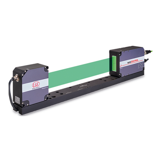
Functional Principle, Technical Data Description The optoCONTROL 2700 is a high-resolution, two-sided telecentric micrometer for measuring dimensional quantities – such as diameters, gaps, positions, and segments – using a shadow-casting or light section process. The sensor consists of a light source and a receiver, which are electrically connected via an eight-pin cable. A mounting rail forms the mechanical connection between the light source and receiver. -
Page 10: Block Diagram
Fig. 2.5: Block Diagram of the ODC2700 Sensor The integrated controller evaluates the image matrix and outputs the measured values via analog or digital interfaces. Various parameterization methods are available, including a web interface (Ethernet) and ASCII commands. optoCONTROL 2700 Seite 10... -
Page 11: Functions
Functional Principle, Technical Data Functions The optoCONTROL 2700 sensor supports the following functions: Edge measurements using a shadow-casting process (edge light-dark; edge dark-light) ● Diameter, width, gap width measurement ● Any segment layers or widths ● Freely selectable edges ●... - Page 12 Standard Standard as calender rolls. Messrichtung: Measurement direction: Standard Standard Schiene (unten) Rail (down) Bereich [%] Range [%] Further information on selection and programming can be found in the measuring programs optoCONTROL 2700 Seite 12...
-
Page 13: Technical Data
Measured with 2 mm testing pin at a measurement distance of 150 mm in measuring field 1 (Z=±2.5 mm). In measuring field 2 (Z= ±10 mm) linearity ≤ 3 µm - 95% confidence interval EtherCAT, PROFINET and EtherNet/IP: Connection either via interface module (see accessories) or as a sensor option Relative humidity % 5 ... 95 (non-condensing) optoCONTROL 2700 Seite 13... - Page 14 8 editable user programs, measured value time diagrams, measured value display in mm / inch, video signal, set-up mode with measuring line and measuring object; menu language German, English Including "sensorTOOL" software for data acquisition and processing, "MedaQLib" Special features programming database optoCONTROL 2700 Seite 14...
-
Page 15: Delivery
► If there is damage or parts are missing, immediately contact the manufacturer or supplier. Optional accessories are listed in the appendix. Storage Temperature range (storage): -20 ... +70 °C Humidity: 5 ... 95% RH (non-condensing) optoCONTROL 2700 Seite 15... -
Page 16: Installation And Assembly
Light source Empfänger Receiver 80 (3.15) 300 (11.8) 152 (5.98) Messebene 22 Measurement plane 22 (.87) 15,3 15.3 (.60) 532 (20.9) (658,5) 658.5 (25.9) Fig. 4.1: Dimensional Drawing of Light Source and Receiver, Dimensions Stated in mm optoCONTROL 2700 Seite 16... -
Page 17: Attachment To Mounting Rail
Ideally, you should mount the mounting rail so that it lies flat against the four M5 mounting holes (highlighted in blue). 80 (3.15) (1.57) 4x M5 4x M5 ø8 4 ø8 4 140 (5.51) 280 (11.0) Fig. 4.3: Dimensional Drawing of Mounting Rail, Standard Mounting Method optoCONTROL 2700 Seite 17... - Page 18 Mount the mounting rail so that it lies flat against the four ø6.6 mounting holes (highlighted in blue). 250 (9.84) 185 (7.28) 4x ø6,6 4x ø6.6 4x M5 4x M5 ø11 6,4 ø11 6.4 ø9,5 4 ø9.5 4 140 (5.51) Fig. 4.4: Dimensional Drawing of Mounting Rail, Optional Mounting Method optoCONTROL 2700 Seite 18...
-
Page 19: Freestanding Mounting
If necessary, loosen the light source for exact positioning. Check the central orientation of the continuous light band both horizontally and vertically. Micro-Epsilon recommends holding a white piece of paper in front of the receiver as a projection screen and covering half of the screen. The strip light must illuminate the glass sheet symmetrically. -
Page 20: Calibrated Measurement Distance
If necessary, take lateral guides into account to avoid lateral movements of the measuring object. Measuring distance 150 Messabstand 150 Measuring field 1 Messfeld 1 Measuring field2 Messfeld 2 5 (.20) 20 (.79) Fig. 4.10: Optimum position of the measuring object within the measuring fields optoCONTROL 2700 Seite 20... -
Page 21: Electrical Connections
Connection light source Fig. 4.12: Electrical connections of receiver Housing screen printing Signal(s) Optional cable ethernet Ethernet SCD2700-5 M12 power / rs422 Supply, RS422, Synchronization PC/SC2700-x in / out Analog output, switching outputs, function inputs SCA2700-x optoCONTROL 2700 Seite 21... -
Page 22: Connection Options
Empfänger ODC2700 Receiver ODC2700 PCSC2700-x SCD2700-3 IF2035-PROFINET IF2030-EtherCAT IF2035-EIP Ethernet IF2001/USB IC2001/USB PS 2020 Sensor supply is done Sensorversorgung erfolgt Sensorversorgung erfolgt by peripheral. durch Peripheriegerät. durch Peripheriegerät. IF2008/PCIE Fig. 4.2: Connection examples with the optoCONTROL 2700 optoCONTROL 2700 Seite 22... -
Page 23: Pin Assignment
Reference ground for switching inputs and outputs Gray Fig. 4.4: Pin Assignment, 17-Pin M12 Male Connector for Analog Output, Switching Inputs, and Switching Outputs 14 15 Fig. 4.14: 17-Pin Female Cable Connector of SCA2700-x, View of Solder Side optoCONTROL 2700 Seite 23... -
Page 24: Supply Voltage
Fig. 4.5: Supply voltage connection Voltage supply only for measuring devices, not to be used for drives or similar sources of impulse interference at the same time. Micro-Epsilon recommends using an optional available power supply unit PS2020 for the sensor. 4.3.6... -
Page 25: Multifunction Input
Connect the inputs to GND in order to trigger the func Grau/Rosa Grey/Pink tion. Grau GND 8 Grey GND 8 Braun Brown Fig. 4.15: Wiring for Multifunction Inputs Signal Multifunction input 1 Multifunction input 2 Multifunction input 3 optoCONTROL 2700 Seite 25... -
Page 26: Switching Output
Fig. 4.7: Switching outputs characteristics Name Output active (e.g. limit Output passive (e.g. no limit value violation) value exceeded) NPN (Low side) PNP (High side) approx. GND Push-pull Push-pull, negated Fig. 4.8: Switching Behavior of Error Outputs optoCONTROL 2700 Seite 26... -
Page 27: Rs422 Connection With Usb Converter If2001/Usb
Symmetrical differential signals according to EIA-422, not electrically separated from the supply voltage. Use a shielded cable with twisted wires, e.g. PC/SC2700-x/OE. IF2001/USB 6-pin terminal block 24 VDC Laser ON 24 VDC GND Multifunction Switch 1 Switch 2 Fig. 4.10: Connecting the Power Supply to the IF2001/USB Converter optoCONTROL 2700 Seite 27... -
Page 28: Synchronization
If baud rate is 10 Mb Link LED Meaning Green If link active If link inactive Flashing If network activity Power LED Meaning Green Supply voltage ON / operation Yellow Booting / bootloader Fig. 4.12: LEDs on Receiver optoCONTROL 2700 Seite 28... -
Page 29: Operation
You can configure the software using the web pages or the ASCII commands integrated in the sensor. Parallel operation with web browser and ASCII commands is possible; the last setting applies. Micro-Epsilon Eltrotec GmbH recommends setting the sensor via the integrated website. To ensure precise measurements, let the sensor warm up for approx. 30 minutes. -
Page 30: Pc With Dhcp
OR: When using DHCP with the DHCP server coupled to the DNS server, access to the sensor is possible using a host name with the structure “ODC2xxx_SN<Serial number>”. ► Start a web browser on your PC. To reach a sensor with serial number “01234567”, type “ODC2xxx_SN01234567” into the address bar of the browser. optoCONTROL 2700 Seite 30... -
Page 31: Access Via Ethernet
Parallel operation with web browser and ASCII commands is possible; the last setting applies. Don’t forget to save. The appearance of the web pages can change depending on the functions and the peripherals. Each page contains pa rameter descriptions and thus tips for configuring the sensor. optoCONTROL 2700 Seite 31... -
Page 32: Video Signal
If this is not possible, the evaluation range (ROI) must be appropriately masked before the light cor rection is performed. ► Switch to the menu > Corrections/Referencing. Press the button. Settings Execute Fig. 5.2: Web Page Light Correction The result of the referencing is stored. optoCONTROL 2700 Seite 32... -
Page 33: Video Signal, Edge Detection
The corresponding x-position in % appears above the graph field. The linearized range lies between the gray shades in the diagram and cannot be changed. Only peaks whose middles lie with in this range can be calculated as a measured value. optoCONTROL 2700 Seite 33... -
Page 34: Presets, Setups, Measurement Configuration Selection
Upon delivery of the sensor from the factory: the web edge, wire measurement, diameter, contour measurement, multi-segment, and gap measurement presets can ● be used, but no setups are available. ● optoCONTROL 2700 Seite 34... - Page 35 Median with 9 values; 2 kHz After parameterization, permanently save all settings in a parameter set so that they will be available again the next time you switch on the sensor. To do this, use the button. Save settings optoCONTROL 2700 Seite 35...
-
Page 36: Setup Mode
Fig. 5.4: Punching Profile with Edge Assignment (Left) and Associated Definition of Segments (Right), Viewed in Direction of Light Source ► Use the tab to start displaying measured values. Measurement chart ► Under “Chart type”, click on Measurement; see figure. optoCONTROL 2700 Seite 36... - Page 37 X axis scaling: The diagram shown above can be enlarged (zoomed in on) with the two sliders on the right and left in the lower entire signal. It can also be moved sideways with the mouse in the middle of the zoom window (four-sided arrow). Chart type selection: Measurement or video signal display. optoCONTROL 2700 Seite 37...
-
Page 38: Advanced Settings
Input level Low ≤ 3 V, High ≥ 8 V Selecting the Input Level ► Switch to the tab > > Settings Inputs Input level. ► Make the desired settings and confirm them by pressing Save settings. optoCONTROL 2700 Seite 38... -
Page 39: Encoder
Set encoder value via software Reset the detection of the first reference mark Selecting the Encoder Setting ► Switch to the tab > > Settings Inputs Encoder inputs. ► Make the desired settings and confirm them by pressing Save settings. optoCONTROL 2700 Seite 39... -
Page 40: Interpolation
● with the Set to value button. ● The start value must be less than the maximum value and is max. 4,294,967,294 (2^32-2). 6.2.3.5 Reset Reference Marker Resets the reference marker detection. optoCONTROL 2700 Seite 40... -
Page 41: Digital Input Assignment
If a reference track is required for the encoder, it is not possible to use the “trigger via multifunction inputs” function. Selecting Digital Inputs ► Switch to the tab > > Settings Inputs Digital input assignment. ► Make the desired settings and confirm them by pressing Save settings. optoCONTROL 2700 Seite 41... -
Page 42: Data Recording
Fig. 6.6: Wide Measuring Line, e.g., Edge Tracing on a Paper Web Changing the Width of the Measuring Line ► Switch to the tab > > and select a suitable width for the Settings Data acquisition Measuring line width measurement task. optoCONTROL 2700 Seite 42... -
Page 43: Measuring Program
SMR dark transitions, start is EMR Fig. 6.2: Edge assignment for the measuring programs Don't forget to save! ► Save individual adjustments to the measurement programs in a setup, see Chap. 6.7.2. optoCONTROL 2700 Seite 43... -
Page 44: Search Direction And Edge Order, Examples
Sensor searches for the first light-dark transi Sensor searches for the first light-dark transi tion and the last dark-light transition, start is tion and the last dark-light transition, start is Fig. 6.5: Edge Assignment for Diameter Measuring Program, Examples optoCONTROL 2700 Seite 44... - Page 45 2: Edge B Sensor searches for all dark-light and light- Sensor searches for all dark-light and light- dark transitions, start is SMR dark transitions, start is EMR Fig. 6.7: Edge Assignment for Segment Measuring Program, Examples optoCONTROL 2700 Seite 45...
-
Page 46: Measurement Direction
The measurement direction determines the reference point for the measured value. The reference point is the mid point of the measuring range (MMR). Receiver Fig. 6.7: Digital Output with Standard Measurement Direction Receiver Fig. 6.8: Digital Output with Inverse Measurement Direction optoCONTROL 2700 Seite 46... -
Page 47: Defining Segments
Fig. 6.10: Individual segment definition Segment definition process ► Switch to the tab > > Settings Data acquisition Segment definition. ► Define the edge references to suit your measuring object. ► Save the resulting setup under a new name. optoCONTROL 2700 Seite 47... -
Page 48: Measuring Rate
You can reset the measured value counter or the timestamp by pressing the relevant button. Counter Reset Procedure ► Switch to the menu > > and click on the relevant button. Settings Data acquisition Counter reset optoCONTROL 2700 Seite 48... -
Page 49: Region Of Interest
"End of range". Defining the region of interest ► Go to the tab > > Settings Data acquisition Evaluation range (ROI). ► Make the desired settings and confirm them by pressing Save settings. optoCONTROL 2700 Seite 49... -
Page 50: Edge Filter
Defining Error Handling ► Switch to the tab > > Settings Data acquisition Error handling. ► Make the desired settings and confirm them by pressing Save settings. optoCONTROL 2700 Seite 50... -
Page 51: Triggering For Data Acquisition
Trigger level Edge Trigger level Falling edge / rising edge Manual selection Number of measured Value values Infinite Software Number of measured Manual selection Value values Infinite Encoder Lower limit Value Upper limit Value Increment Value optoCONTROL 2700 Seite 51... - Page 52 Starts data acquisition/output via the encoder input. Encoder Defining Triggering ► Switch to the tab > > Triggering. Settings Data acquisition ► Make the desired settings and confirm them by pressing Save settings. optoCONTROL 2700 Seite 52...
-
Page 53: Triggering For Measured Value Acquisition
SU4-1 level converter, which is available as an optional accessory. Sync + / Trigger +24 V TTL / HTL Trigger Sync - / Trigger source RS422 Fig. 6.15: Adjustment of the Level from HTL to RS422 Using the SU4-1 Level Converter optoCONTROL 2700 Seite 53... -
Page 54: Signal Processing
Tilt correction is likewise possible in setups based on these. multi-segment, Activating Tilt Correction ► Switch to the tab and select On. Settings > Signal processing > Tilt correction The tilt correction function can handle a tilt angle of up to ±45° affecting the target. optoCONTROL 2700 Seite 54... -
Page 55: Calculation
Select a program (1), e.g., average. ● Define the parameters (2). ● Define the data source(s) (3). ● Enter a block name (4). ● Click on the button. ● Apply calculation Fig. 6.10: Sequence for Program Selection optoCONTROL 2700 Seite 55... -
Page 56: Definitions
Block 1 Calculation Processing sequence: Determination of edges Calculation of differences (diameter, gap, segments) and center axes Error handling in the case of no valid measured value Spike correction of measured values Calculation functions (blocks) Statistics optoCONTROL 2700 Seite 56... -
Page 57: Averaging
Averaging is disabled by default on the sensor. Defining Measurement Averaging ► Switch to the tab > > Calculation. Settings Signal processing ► Make the desired settings and confirm them by pressing Save settings. optoCONTROL 2700 Seite 57... -
Page 58: Moving Average
MW = measured value = average value or output value Recursive averaging allows for very strong smoothing of the measurements, however it requires long response times for measurement jumps. The recursive average value shows low-pass behavior. optoCONTROL 2700 Seite 58... -
Page 59: Median
To eliminate dirt or roughness in a rough, dusty or dirty environment ● Further averaging can be used after the median filter ● Fig. 6.14: Median, N = 7 Fig. 6.17: Signal Curve – Profile without Median (Left), with Median N = 9 (Right) optoCONTROL 2700 Seite 59... -
Page 60: Post-Processing
1: Edge A / ... / 8: Edge B / 1: Diameter / ... / 8: Diameter / 1: Cen Multi-segment preset ter / ... / 8: Center Master value Value Master signal Edge A / Edge B / Diameter / Center measure- preset ment Value Master value Inactive optoCONTROL 2700 Seite 60... -
Page 61: Zeroing/Mastering Procedure
During mastering, the sensor characteristic is moved in parallel. Moving the characteristic reduces the relevant measuring range of a sensor (the further master value and master position are located, the greater the reduction). Measuring range 100 % Fig. 6.18: Moving the Characteristic During Mastering optoCONTROL 2700 Seite 61... -
Page 62: Statistics
1: Edge A / ... / 8: Edge B / 1: Diameter / ... / 8: Diameter / Statistic signal Multi-segment preset 1: Center / ... / 8: Center Statistical value Value Edge A / Edge B / Diameter / Center Statistic signal measure- preset ment Statistical value Value optoCONTROL 2700 Seite 62... -
Page 63: Data Reduction
Ethernet Defining a Data Reduction ► Switch to the tab > > Settings Postprocessing Data reduction. ► Make the desired settings and confirm them by pressing Save settings. optoCONTROL 2700 Seite 63... -
Page 64: Triggering For Measured Value Output
Data output only starts when the interface is activated, see Chap. 6.6.5. Baud rate and signal selection ► Go to the tab > > Settings Outputs Data output RS422. ► Make the desired settings and confirm them by pressing Save settings. optoCONTROL 2700 Seite 64... -
Page 65: Data Output Ethernet
► Switch to the > > tab. Settings Outputs Data output Ethernet ► Make the desired settings and confirm them by pressing Save settings. Data output only starts when the interface is activated, see Chap. 6.6.5. optoCONTROL 2700 Seite 65... -
Page 66: Analog Output
(da search direction measurement direction ta acquisition) affect the analog output. Receiver Fig. 6.24: Scaling of Analog Signal 4 ... 20 mA, Example of Edge Tracing, Search and Measurement Directions: Standard optoCONTROL 2700 Seite 66... -
Page 67: Switching Outputs
Value Value Upper limit mm Switching level in case of NPN / PNP / Push-pull / Push- error pull negated Value Output duration ms Inactive The selected preset or setup determines which signals are possible. [10] optoCONTROL 2700 Seite 67... -
Page 68: Setting Limit Values
In the case of the Ethernet interface, the data intended for transmission is selected in the Ethernet data output section see Chap. 6.6.2. Selecting/Activating Interfaces ► Switch to the tab > > Settings Outputs Data output. Fig. 6.25: Activating Output Interfaces optoCONTROL 2700 Seite 68... -
Page 69: Ethernet Settings
Active / Inactive Automatic Number of frames Specify number Value Defining the Ethernet Interface ► Switch to the tab > > Settings Outputs Ethernet settings. ► Make the desired settings and confirm them by pressing Save settings. optoCONTROL 2700 Seite 69... -
Page 70: System Settings
Click on the desired setup with the left mouse button. dialog opens. dialog opens. Measurement settings Measurement settings Click on the button. Click on the button. Export Browse A Windows dialogue for file selection opens. Select the desired file and click on the button. Open optoCONTROL 2700 Seite 70... -
Page 71: Import & Export
Select/deselect the checkboxes to determine which actions Download should be performed. area. The resulting file name for the adjacent example is <...\ Click on the button. Downloads\ODC2700_BASICSETTINGSTINGS_MEASSET- Transmit file TINGS..JSON> Fig. 6.22: Exchanging Parameter Sets with a PC/Notebook, Options and Procedure optoCONTROL 2700 Seite 71... -
Page 72: Access Authorization
All passwords are case-sensitive. Numbers are allowed. Special characters are not Password permitted. User / Professional User level on re Defines the user level that is enabled after restart. start Micro-Epsilon recommends the selection Professional here. optoCONTROL 2700 Seite 72... -
Page 73: Resetting The Sensor
Light Source This allows the light source to be switched on and off in the sensor. Light Source On/Off ► Switch to the tab > > Settings System settings Light source. ► Select the desired function. optoCONTROL 2700 Seite 73... -
Page 74: Disclaimer
Micro-Epsilon or to your distributor / retailer. Micro-Epsilon undertakes no liability whatsoever for damage, loss or costs caused by or related in any way to the product, in particular consequential damage, e.g., due to non-observance of these instructions/this manual, ●... -
Page 75: Service, Repair
If the cause of a fault cannot be clearly identified, please send the entire measuring system to: MICRO-EPSILON Eltrotec GmbH Manfred-Wörner-Straße 101 73037 Göppingen / Germany Tel: +49 (0) 7161 / 98872-300 Fax: +49 (0) 7161 / 98872-303 E-Mail: eltrotec@micro-epsilon.de www.micro-epsilon.com/contact/worldwide/ Web: www.micro-epsilon.com optoCONTROL 2700 Seite 75... -
Page 76: Decommissioning, Disposal
Here you can inform yourself about the re spective national collection and return points. - Old devices can also be returned for disposal to Micro-Epsilon at the address given in the imprint at https:// www.micro-epsilon.com/legal-details. - We would like to point out that you are responsible for deleting the measurement-specific and personal data on the old devices to be disposed of. -
Page 77: Factory Settings
Encoder, reference track no effect Web interface language German Mastering, Zeroing Measuring Rate 2.5 kHz Region of interest 0 ... 100 % Triggering Measurement configuration, preset Web edge Signal Quality Balanced Statistics Edge A, 256 values optoCONTROL 2700 Seite 77... -
Page 78: Optional Accessories
IC2001/USB IC2001/USB single-channel RS422/USB converter cable IF2035-EtherCAT Interface module for connection to EtherCAT, PROFINET, or EtherNet/IP of a Micro-Epsilon sensor with RS485 or RS422 IF2035-PROFINET interface; suitable for cable PC/SC2700-x, top-hat rail hous IF2035-EIP ing, incl. GSDML file for software integration into the PLC... - Page 79 Bus coupler; for use on an EtherCAT master; can only be used together with EK1122 EK1122 bus terminal Bus terminal; for use in conjunction with a bus coupler and SCD2700-x on an EtherCAT master; 2-port EtherCAT junc tion for two sensor signals optoCONTROL 2700 Seite 79...
-
Page 80: Ascii Communication
Command response Cursor – the sensor is ready for the input. E<ddd> <Msg>: Error message, execution canceled ● W<ddd> <Msg>: Warning, execution in progress ● <ddd>: Three-digit number ● <Msg>: Message ● Format description (): Grouping ● optoCONTROL 2700 Seite 80... -
Page 81: Retrieving Sensor Information
ON: The command name and the command reply or an error message is output. ● OFF: Nothing but the command reply or an error message is output. ● 12.2.4 Parameter overview PRINT [ALL] This command outputs a complete or partial list of all configuration parameters and their values. optoCONTROL 2700 Seite 81... -
Page 82: Synchronization
GETUSERLEVEL Outputs the current user level. 12.3.4 Setting the user level on restart (standard user) STDUSER [USER|PROFESSIONAL] Sets the user level to Standard. The user is also stored after a RESET and restart of the system. optoCONTROL 2700 Seite 82... -
Page 83: Changing The Password
ROI: Only checks the ROI (region of interest, defined by the ROI command) ● OBJ_IGNORE: Ignores targets (measuring objects); the soiling check is only performed for the exposed sensor area. ● Completely dark areas with sharp edges are excluded from the check. optoCONTROL 2700 Seite 83... -
Page 84: Soilingstatus
NONE: Ignores all trigger sources ● SYNCTRIG: Uses the Sync/Trig input ● TRIGIN: Uses the TrigIn input ● SOFTWARE: Uses the software trigger generated via the TRIGGERSW command ● ENCODER1: The encoder is used for triggering ● optoCONTROL 2700 Seite 84... -
Page 85: Effect Of Triggering
If the value is set to 0 and the encoder value is between min. and max., all values are output. If <value_of_step_size> is greater than 0, then TRIGGERENCMIN and TRIGGERENCMAX should be a multiple of <val ue_of_step_size>. See TRIGGERENCMIN and TRIGGERENCMAX value_of_step_size: 0 .. 2^31-1 ● optoCONTROL 2700 Seite 85... -
Page 86: Encoder Trigger Minimum
12.7.5 Maximum Encoder Value ENCMAX [<value>] This command allows you to set a maximum encoder value. The maximum value has to be greater than the start value of the ENCVALUE command. value: 1 ... 2^32-1 ● optoCONTROL 2700 Seite 86... -
Page 87: Resetting The Encoder Reference Track
TCP Settings TCPKEEPALIVE [ON|OFF] The settings are applied to new TCP connections. Existing connections remain unaffected. The possible command parameters are: ON: Activates the TCP keep-alive function (see RFC 1122) ● OFF: Deactivates the TCP keep-alive function optoCONTROL 2700 Seite 87... -
Page 88: Terminating Resistor
Factory Reset SETDEFAULT ALL | MEASSETTINGS | BASICSETTINGS Resets the sensor to its factory settings. ALL: Deletes all settings and loads the factory settings ● MEASSETTINGS: Deletes all measurement settings ● BASICSETTINGS: Deletes all basic settings ● optoCONTROL 2700 Seite 88... -
Page 89: Measurement Settings
<name new> The name of a user-specific setting (setup). Names must have at least 2 characters and can contain a ● maximum of 31. The following characters are permitted: a-zA-Z0-9_. The names of the presets and the designation “AUTO” are not permitted. optoCONTROL 2700 Seite 89... -
Page 90: Measurement
INVERSE: The measurement direction begins at the end of the measuring range (EMR) and moves toward the start of ● the measuring range (mounting rail). 12.10.4 Number of Expected Edges EXPEDGES <value> Defines the number of expected edges for the ERROROUT command. Value: 0 ... 251 ● optoCONTROL 2700 Seite 90... -
Page 91: Defining Segments
Outputting a Signal with the Edge Filter EDGEFILTER1SIGNAL [<signal>] EDGEFILTER2SIGNAL [<signal>] Sets or displays the selected signal for edge filter calculation 1 or 2. The META_EDGEFILTER1SIGNAL and META_EDGEFILTER2SIGNAL commands list all the available signals that can be used for the output. optoCONTROL 2700 Seite 91... -
Page 92: List Of Edge Filter Signals
List of predefined functions: MEDIAN: Sorts the last <median data count> values and outputs the middle value. Useful, for example, for eliminating ● spikes. MOVING: Outputs an average of the last <moving data count> values. ● optoCONTROL 2700 Seite 92... -
Page 93: List Of Possible Calculation Signals, Computing Module
Depth: 2|4|8|...|8192|16384 ● Number of measured values used to calculate the statistical values of a signal. 12.11.6 Selecting Statistic Signals META_STATISTIC Lists all the signals configured with STATISTICSIGNAL that can be selected for the STATISTIC command. optoCONTROL 2700 Seite 93... -
Page 94: Resetting Statistics
-0.5 mm is applied to <signal>. The RESET function resets the offset to 0. The display output provides a list of signals and shows the word ACTIVE if mastering is currently active for the signal concerned. If mastering is not active, it shows the word INACTIVE. signal: A measurement data signal (see META_MASTER) ● optoCONTROL 2700 Seite 94... -
Page 95: Data Output
Selecting the Measured Values to be Output 12.13.1 Selecting Ethernet Signals OUT_ETH [<signal1>] [<signal2>] ... [<signalN>] Defines the signals that are to be output via Ethernet. The META_OUT_ETH command lists all the signals available for the output. optoCONTROL 2700 Seite 95... -
Page 96: Signals For Ethernet Output
● ERRORLIMIT: Error limit defined by the commands ● ERRORLIMITSIGNAL1, ERRORLIMITVALUES1, and ERRORLIMITCOMPARETO1 ERRORLIMITSIGNAL2, ERRORLIMITVALUES2, and ERRORLIMITCOMPARETO2 ERRORLIMITSIGNAL3, ERRORLIMITVALUES3, and ERRORLIMITCOMPARETO3 EXPEDGES: Error output if CNT_EDGE does not match the value of the EXPEDGES command. ● optoCONTROL 2700 Seite 96... -
Page 97: Possible Signals For Error Outputs
The ERRORLIMITCOMPARETO1, ERRORLIMITCOMPARETO2, and ERRORLIMITCOMPARETO3 commands define whether the lower limit value, upper limit value, or both limit values should be applied. <lower limit [mm]> = -2147.0 ... 2147.0 ● <upper limit [mm]> = -2147.0 ... 2147.0 ● optoCONTROL 2700 Seite 97... -
Page 98: Switching Output Hold Period
Scaling of the Analog Output ANALOGSCALEMODE [STANDARD|TWOPOINT] Set or adjust the scaling of the analog output. STANDARD: Use measuring range of sensor ● TWOPOINT: The measured values are scaled to the range specified by the ANALOGSCALERANGE command. ● optoCONTROL 2700 Seite 98... -
Page 99: Selecting The Scaling Range For The Analog Output
Each pixel of the video signal is represented by a 16-bit word. The value range used is 0 … 4095. The measured values are represented as a 32-bit signed integer with a resolution of 10 nm. optoCONTROL 2700 Seite 99... -
Page 100: Data Format Of Rs422 Interface
0 ... 1 View LSB as the first pixel of the im Bright pixel (512 x 128 pixels * 1 bit LIGHT Light-corrected signal 0 ... 1023 value / 1024 * 100 (2048 x 16 bits) optoCONTROL 2700 Seite 100... - Page 101 De grees *[A|B|C|D] 0 ... 7FFFFEFF value / 100000 0x7FFFFF04 No edge is present 0x7FFFFF07 Measured value cannot be calculated 0x7FFFFF08 Measured value is out side the displayable range USERNAMED 0 ... 7FFFFEFF wie *[A|B|C|D] VALUES optoCONTROL 2700 Seite 101...
-
Page 102: Index
MICRO-EPSILON Eltrotec GmbH Manfred-Wörner-Straße 101 73037 Göppingen / Germany Tel: +49 (0) 7161 / 98872-300 X9751487-A012074MSC E-Mail: eltrotec@micro-epsilon.de © MICRO-EPSILON MESSTECHNIK www.micro-epsilon.com/contact/worldwide/...
Need help?
Do you have a question about the optoCONTROL 2700 and is the answer not in the manual?
Questions and answers