
Related Manuals for MICRO-EPSILON optoControl 1200


Summary of Contents for MICRO-EPSILON optoControl 1200
- Page 1 Betriebsanleitung Operating Instructions optoCONTROL 1200/1201 ODC1200 ODC1200/90 ODC1201...
- Page 2 Kompakter Lichtmengensensor Compact light quantity measurement sensor MICRO-EPSILON Eltrotec GmbH Manfred-Wörner-Straße 101 73037 Göppingen / Germany Tel. +49 (0) 7161 / 98872-300 Fax +49 (0) 7161 / 98872-303 e-mail eltrotec@micro-epsilon.de www.micro-epsilon.com...
-
Page 3: Table Of Contents
Elektrische Anschlüsse, Versorgungs- und Ausgangskabel ................17 Betrieb ............................18 Inbetriebnahme ..............................18 Versorgungsspannung ............................ 18 LED‘s, Potentiometer optoCONTROL 1200 ....................19 LED‘s, Potentiometer optoCONTROL 1200/90 ....................20 LED‘s, Potentiometer optoCONTROL 1201 ....................21 Ein- und Ausgänge ............................22 Grenzwertausgang ............................24 Analogausgang .............................. - Page 4 Haftung für Sachmängel ......................27 Service, Reparatur ........................27 Außerbetriebnahme, Entsorgung .................... 28 Anhang ............................28 optoCONTROL 1200/1201...
-
Page 5: Sicherheit
Vermeiden Sie Stöße und Schläge auf die Lichtquelle / Empfänger > Beschädigung oder Zerstörung des Sensors Versorgungsspannung darf angegebene Grenzen nicht überschreiten. > Beschädigung oder Zerstörung des Sensors Schützen Sie das Anschlusskabel vor Beschädigung > Zerstörung des Sensors > Ausfall des Messgerätes optoCONTROL 1200/1201 Seite 5... -
Page 6: Hinweise Zur Ce-Kennzeichnung
Produkte, die das CE-Kennzeichen tragen, erfüllen die Anforderungen der zitierten EU-Richtlinien und die dort aufgeführten harmonisierten europäischen Normen (EN). Die EU-Konformitätserklärung wird gemäß der EU-Richtlinie, Artikel 10, für die zuständige Behörde zur Verfügung gehalten bei MICRO-EPSILON Eltrotec GmbH Manfred-Wörner-Straße 101 73037 Göppingen / Deutschland Das Messsystem ist ausgelegt für den Einsatz im Industriebereich und erfüllt die Anforderungen. -
Page 7: Bestimmungsgemäße Verwendung
Beeinträchtigung oder dem Ausfall der Funktion führt. Die Schutzklasse ist auf Wasser begrenzt (keine eindringenden Flüssigkeiten oder ähnliches). - Betriebstemperatur: 0 to +50 °C - Lagertemperatur: -20 °C to +70 °C - Luftfeuchtigkeit: 5 - 90 % (nicht kondensierend) - Umgebungsdruck: Atmosphärendruck optoCONTROL 1200/1201 Seite 7... -
Page 8: Laserklasse
Warnschilder für Deutschland und die USA sind beigelegt und vom Anwender für die jeweils gültige Region vor der ersten Inbetriebnahme anzubringen. Class 1 Laser Product LASER KLASSE 1 IEC 60825-1: 2008-05 nach DIN EN 60825-1: 2008-05 Abb. 1 Laserwarnschild, IEC-Standard Abb. 2 Laserwarnschild, deutsch optoCONTROL 1200/1201 Seite 8... -
Page 9: Funktionsprinzip, Technische Daten
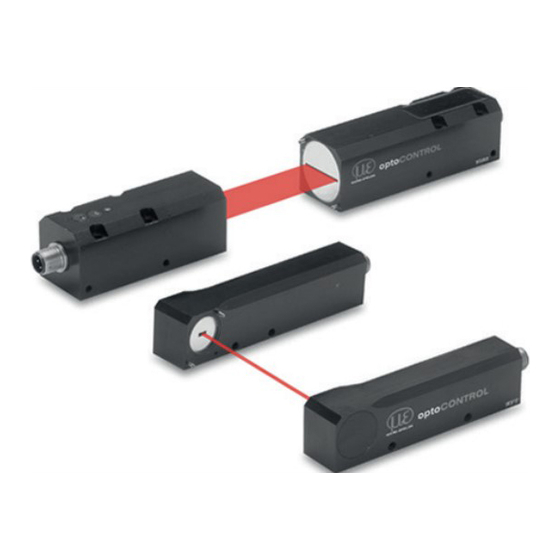
Linse Interferenzfilter Blende Linse Polarisationsfilter Abb. 3 Messprinzip optoCONTROL 1200/1201 Lichtquelle und Empfänger bilden eine Einheit und dürfen nicht getauscht werden. Aufbau eines kompletten Messkanals Das optoCONTROL 120x besteht aus einer Lichtquelle und einer Empfängereinheit. Die gesamte Controlle- relektronik ist im Empfängergehäuse untergebracht und ein zusätzlicher Controller ist nicht nötig. Empfän- ger und Lichtquelle können stufenlos zueinander montiert werden, die 90 °... -
Page 10: Technische Daten
0 ... 50 °C Lagertemperatur -20 ... 70 °C Betriebsspannung 12 - 32 VDC, verpol- und überlastsicher stehend M4 x 5 mm ø 4,1 mm Befestigungsbohrungen seitlich liegend M5 x 8 mm M4 x 6 mm optoCONTROL 1200/1201 Seite 10... -
Page 11: Lieferung
Prüfen Sie die Lieferung nach dem Auspacken sofort auf Vollständigkeit und Transportschäden. Bei Schäden oder Unvollständig- keit wenden Sie sich bitte sofort an den Lieferanten. Lagerung Lagertemperatur: -20 bis +70 °C Luftfeuchtigkeit: 5 - 95 % (nicht kondensierend) optoCONTROL 1200/1201 Seite 11... -
Page 12: Installation Und Montage
Zur Ausrichtung sind Anschlagwinkel oder Schiene geeignete Hilfsmittel. Durchsteckverschraubung Gehäuse Durchstecklänge Schraube Scheibe Anziehdrehmoment pro Schraube ISO 4762 - A2 ISO 7089 - A2 µ = 0,12 ODC1200-...-T A4,3 ODC1200-...-R A4,3 ODC1200-90-...-T A4,3 ODC1200-90-...-R A4,3 ODC1201-...-T ODC1201-...-R optoCONTROL 1200/1201 Seite 12... - Page 13 1) Einschraubtiefe (tragende Gewindelänge 2,6) Empfohlenes Anziehdrehmoment -> max. +10 % zulässig, min. -20 % nicht unterschreiten Die in der Tabelle genannten Anziehdrehmomente sind Richtwerte und können je nach Anwendungsfall variieren. Grundlage der Betrachtungen: µ =0,12 optoCONTROL 1200/1201 Seite 13...
- Page 14 10 x 0,3 ODC1200-16 16 x 2 16 x 0,3 M4 x 5 M4 x 5 Laserlicht max. 5000 M5 x 8 M5 x 8 Abb. 4 Maßzeichnung ODC 1200, Messbereiche 2/5/10/16 mm, Abmessungen in mm, nicht maßstabsgetreu optoCONTROL 1200/1201 Seite 14...
- Page 15 Abb. 5 Maßzeichnung ODC 1201, Messbereiche 20/30 mm, Abmessungen in mm, nicht maßstabsgetreu Modell Sender Empfänger ODC1201-20 20 x 2 20 x 0,3 Blendenmaße (A x B) in mm ODC1201-30 20 x 2 30 x 0,3 optoCONTROL 1200/1201 Seite 15...
- Page 16 2 x 2 2 x 0,3 ODC1200/90-5 5 x 2 5 x 0,3 ODC1200/90-10 10 x 2 10 x 0,3 ODC1200/90-16 16 x 2 16 x 0,3 Abb. 7 Maßzeichnung ODC 1200/90, Abmessungen in mm, nicht maßstabsgetreu optoCONTROL 1200/1201 Seite 16...
-
Page 17: Elektrische Anschlüsse, Versorgungs- Und Ausgangskabel
Die Betriebsspannung wird vorzugsweise über ein abgeschirmtes Kabel angeschlossen, z.B. über das Versorgungskabel PC1200-5. Führen Sie den Kabelschirm auf eine Potentialausgleichsklemme in der Nähe des Netzteiles. 26,5 Biegeradius PC1200: minimal 52 mm ø 5,2 41,5 Abb. 8 PC1200-5 Abb. 9 PC1200/90-5 optoCONTROL 1200/1201 Seite 17... -
Page 18: Betrieb
Nennwert: 24 VDC (12 ... 32 VDC, max. 100 mA). Verwenden Sie ein fehlerfreies und stabilisiertes Netzteil. Verwenden Sie das Netzteil ausschließlich für Messgeräte, nicht gleichzeitig für Antriebe oder ähnliche Impulsstörquellen, um Rauschen und Interferenzen zu vermeiden. optoCONTROL 1200/1201 Seite 18... -
Page 19: Led's, Potentiometer Optocontrol 1200
Betrieb LED‘s, Potentiometer optoCONTROL 1200 Versorgung Verstärkung Schaltschwelle Schaltzustand Einstellung Lichtquelle Empfänger Potentiometer Zustand Beschreibung Ausgang < 9,5 V Einstellung grün Ausgang > 9,5 V Analogspannung mit Verstärkungspoti auf 10 V einstellen gelb Analogspannung < Schaltschwelle Schaltzu- stand grün Analogspannung > Schaltschwelle Schaltschwelle Drehen im Uhrzeigersinn: Schaltschwelle erhöhen, Bereich 0 ... -
Page 20: Led's, Potentiometer Optocontrol 1200/90
Betrieb LED‘s, Potentiometer optoCONTROL 1200/90 Versorgung Verstärkung Schaltschwelle Schaltzustand Einstellung Lichtquelle Empfänger Potentiometer Zustand Beschreibung Ausgang < 9,5 V Einstellung grün Ausgang > 9,5 V Analogspannung mit Verstärkungspoti auf 10 V einstellen gelb Analogspannung < Schaltschwelle Schaltzu- stand grün Analogspannung > Schaltschwelle Schaltschwelle Drehen im Uhrzeigersinn: Schaltschwelle erhöhen, Bereich 0 ... -
Page 21: Led's, Potentiometer Optocontrol 1201
Drehen im Uhrzeigersinn: Verstärkung erhöhen, Bereich 0 ... 10 V gelb Analogspannung < Schaltschwelle Schaltzu- stand grün Analogspannung > Schaltschwelle Ausgang < 9,5 V Einstellung grün Ausgang > 9,5 V Analogspannung mit Verstärkungspoti auf 10 V einstellen optoCONTROL 1200/1201 Seite 21... -
Page 22: Ein- Und Ausgänge
GND (0 V) schwarz Pin 2 verbunden mit 5 ... 24 VDC: Laser aus Schirm Gehäuse - - - MICRO-EPSILON Eltrotec GmbH empfiehlt die Verwendung des Versorgungs- und Ausgangskabels PC1200. Dieses Kabel ist als optionales Zubehör erhältlich. optoCONTROL 1200/1201 Seite 22... - Page 23 0 ... 10 VDC < 100 mA Last Abb. 13 Anschluss Empfänger, Last mit +24 VDC verbunden, (NPN aktiv Lichtmenge > Grenzwert) 1) High side/low side Schalter. Treibt die Last in Richtung +24 VDC oder nach GND. optoCONTROL 1200/1201 Seite 23...
-
Page 24: Grenzwertausgang
Betrieb Grenzwertausgang Das optoCONTROL 1200/1200/90/1201 erlaubt eine unabhängige Einstellung des Grenzwertes, siehe Kap. und Kap. (für die Lage des Grenzwertpotentiometers). Die Schaltschwelle des Grenzwertausgangs ist frei schaltbar und wird in Abb. 14 bei 5 V aktiviert: - PNP aktiv, wenn Lichtmenge unter dem Grenzwert - NPN aktiv, wenn Lichtmenge über dem Grenzwert... -
Page 25: Analogausgang
10,0 V = 100 % Messbereich (kein Messobjekt) MB = Messbereich Berechnung eines Wertes: Beispiel: = 4,6 V MB [mm] * (10 V - U Messbereich = 10 mm x [mm] = 10 V Werte = 5,4 mm optoCONTROL 1200/1201 Seite 25... -
Page 26: Hinweise Für Den Betrieb
Hierfür ist ein Optik-Antistatikpinsel geeignet oder Abblasen der Scheiben mit entfeuchteter, sauberer und ölfreier Druckluft. Feuchtreinigung Benutzen Sie zum Reinigen der Schutzscheibe ein sauberes, weiches, fusselfreies Tuch oder Linsenreini- gungspapier und reinen Alkohol (Isopropanol). Verwenden Sie auf keinen Fall handelsübliche Glasreiniger oder andere Reinigungsmittel. optoCONTROL 1200/1201 Seite 26... -
Page 27: Haftung Für Sachmängel
Haftung für Sachmängel Alle Komponenten des Geräts wurden im Werk auf die Funktionsfähigkeit hin überprüft und getestet. Sollten jedoch trotz sorgfältiger Qualitätskontrolle Fehler auftreten, so sind diese umgehend an MICRO-EPSILON El- trotec zu melden. Die Haftung für Sachmängel beträgt 12 Monate ab Lieferung. Innerhalb dieser Zeit werden fehlerhafte Teile, ausgenommen Verschleißteile, kostenlos instandgesetzt oder ausgetauscht, wenn das Gerät kostenfrei an... -
Page 28: Außerbetriebnahme, Entsorgung
JU1200-HT Justageplatte ODC 12xx zur horizontalen Montage der Lichtquelle JU1200-HR Justageplatte ODC 12xx zur horizontalen Montage des Empfängers JU1200-VT Justageplatte ODC 12xx zur vertikalen Montage der Lichtquelle JU1200-VR Justageplatte ODC 12xx zur vertikalen Montage des Empfängers optoCONTROL 1200/1201 Seite 28... - Page 29 Max. Distanz Lichtquelle / Empfänger 500 mm Empfänger Sender ODC1200/90 ODC1200/90 BR1200L BR1200L Klammer zur Klammer zur Montage als Montage als C-Rahmen C-Rahmen JU1200-VR JU1200-VT Justageplatte Justageplatte für Empfänger für Sender Montageschiene ODC1202-L, in verschiedenen Längen erhältlich optoCONTROL 1200/1201 Seite 29...
- Page 31 Electrical Connections, Power Supply and Output Cable ................45 Operation ..........................46 Getting Ready for Operation ..........................46 Operating Voltage ............................46 LED Functions, Potentiometer optoCONTROL 1200 ..................47 LED Functions, Potentiometer optoCONTROL 1200/90 ................. 48 LED Functions, Potentiometer optoCONTROL 1201 ..................49 Inputs and Outputs ............................50 Switching Output .............................
- Page 32 Warranty ............................ 55 Service, Repair ........................55 Decommissioning, Disposal ....................56 Appendix ........................... 56 optoCONTROL 1200/1201...
-
Page 33: Safety
Avoid shock and vibration to the light source and receiver. > Damage to the sensor Supply voltage must not exceed specified limits. > Damage to the sensor Protect cables from damage. > Damage to the sensor > Failure of the measurement device optoCONTROL 1200/1201 Page 33... -
Page 34: Notes On Ce Identification
Products which carry the CE mark satisfy the requirements of the quoted EU directives and the European standards (EN) listed therein. The EC declaration of conformity is kept available according to EC regulation, article 10 by the authorities responsible at MICRO-EPSILON Eltrotec GmbH Manfred-Wörner-Straße 101 73037 Göppingen / Germany The measuring system is designed for use in industry and satisfies the requirements. -
Page 35: Proper Use
≤ 0.39 mW. The sensors are classified in Laser Class 1 (Class I). The accessible radiation is harmless under predictable conditions. The following warning labels are attached to the cover of the sensor housing: Class 1 Laser Product IEC 60825-1: 2008-05 IEC label Only for USA optoCONTROL 1200/1201 Page 35... - Page 36 If the warning labels are disguised in operation mode the user must add additional warning labels. Fig. 1 True reproduction of the light source with its actual location of the warning labels optoCONTROL 1200/1201 Page 36...
-
Page 37: Functional Principle, Technical Data
Glass lens Interference filter Aperture Lens Polarization filter Fig. 2 Measurement principle optoCONTROL 1200/1201 The light source and receiver form an unit and must not be switched. Structure of a Complete Measurement System The optoCONTROL 120x consists of a light source and a receiver unit. The complete control electronics is in- side the receiver and no additional controller is necessary. -
Page 38: Technical Data
-20 ... 70 °C (-4 to +158 °F) Operating voltage 12 - 32 VDC, reverse polarity protection straight up M4 x 5 mm ø 4.1 mm Mounting holes horizontal M5 x 8 mm M4 x 6 mm optoCONTROL 1200/1201 Page 38... -
Page 39: Delivery
Check for completeness and shipping damage immediately after unpacking. In case of damage or missing parts, please contact the manufacturer or supplier. Storage Storage temperature: -20 to +70 °C (-4 to +158 °F) Humidity: 5 - 95 % (non-condensing) optoCONTROL 1200/1201 Page 39... -
Page 40: Installation
For alignment try squares or rails are suitable aids. Bolt connection Housing Push through Screw Washer Tightening torque length per screw ISO 4762 - A2 ISO 7089 - A2 µ = 0.12 ODC1200-...-T A4.3 ODC1200-...-R A4.3 ODC1200-90-...-T A4.3 ODC1200-90-...-R A4.3 ODC1201-...-T ODC1201-...-R optoCONTROL 1200/1201 Page 40... - Page 41 Recommended tightening torque -> max. +10 % valid, min. -20 % do not fall below The tightening torques named in the table are recommended values and can vary according to each case of application. Basis of consideration: µ =0.12 optoCONTROL 1200/1201 Page 41...
- Page 42 M4 x 5 Laser light max. 5000 (197) M5 x 8 M5 x 8 45 (1.77) 12 (.47) (.98) (.39) (.79) (.94) Fig. 3 Dimensional drawing ODC 1200, ranges 2/5/10/16 mm, dimensions in mm, not to scale optoCONTROL 1200/1201 Page 42...
- Page 43 Light source Receiver ODC1201-20 20 x 2 (.79 x .08) 20 x 0.3 (.79 x .01) Aperture dimensions (A x B) in mm ODC1201-30 30 x 2 (1.18 x .08) 30 x 0.3 (1.18 x .01) optoCONTROL 1200/1201 Page 43...
- Page 44 Fig. 5 Dimensional drawing ODC 1200/90, dimensions in mm, not to scale ODC1200/90-10 10 x 2 (.39 x .08) 10 x 0.3 (.39 x .01) ODC1200/90-16 16 x 2 (.63 x .08) 16 x 0.3 (.63 x .01) optoCONTROL 1200/1201 Page 44...
-
Page 45: Electrical Connections, Power Supply And Output Cable
Connect the cable shield to a ground terminal in close proximity to the power supply unit. 26.5 (1.04) Bending radius PC1200: minimal 52 mm ø 5.2 (.20 dia.) 41.5 (1.63) Fig. 6 PC1200-5 Fig. 7 PC1200/90-5 optoCONTROL 1200/1201 Page 45... -
Page 46: Operation
Nominal value: 24 VDC (12 ... 32 VDC, max. 100 mA). Use a clean and regulated power supply unit dedicated for measurement instruments only. Do not use a voltage from other electronic equipment to avoid noise and interference. optoCONTROL 1200/1201 Page 46... -
Page 47: Led Functions, Potentiometer Optocontrol 1200
Operation LED Functions, Potentiometer optoCONTROL 1200 Power Gain Threshold Limit state Adjustment Light source Receiver Potentiometer State Description Output < 9.5 V Adjustment green Output > 9.5 V Use the gain pot to adjust the analog output up to 10 V. -
Page 48: Led Functions, Potentiometer Optocontrol 1200/90
Operation LED Functions, Potentiometer optoCONTROL 1200/90 Power Gain Threshold Limt state Adjustment Light source Receiver Potentiometer State Description Output < 9.5 V Adjustment green Output > 9.5 V Use the gain pot to adjust the analog output up to 10 V. -
Page 49: Led Functions, Potentiometer Optocontrol 1201
Analog voltage < threshold value Limit state green Analog voltage > threshold value Output < 9.5 V Adjustment green Output > 9.5 V Use the gain pot to adjust the analog output up to 10 V. optoCONTROL 1200/1201 Page 49... -
Page 50: Inputs And Outputs
Pin 2 connected with 5 ... 24 VDC: Laser off Screen Housing - - - MICRO-EPSILON Eltrotec GmbH recommends the use of the PC1200 power supply and output cable. This cable is an optional accessory. optoCONTROL 1200/1201 Page 50... - Page 51 0 ... 10 VDC < 100 mA Load Fig. 10 Receiver wiring, load connected with +24 VDC, (NPN active light quantity > threshold) 1) High side/low side switch. The load can be connected to +24 VDC or to GND. optoCONTROL 1200/1201 Page 51...
-
Page 52: Switching Output
Operation Switching Output The optoCONTROL 1200/1200/90/1201 enables individual setting of the threshold value, see Chap. Chap. (for the location of the threshold potentiometer). The limit output is freely adjustable and is activa- ted in Fig. 11 at 5 V: - PNP active if light quantity below limit... -
Page 53: Analog Output
10.0 V = 100 % measuring range (no target) MR = Measuring range Calculation of a value: Example: = 4.6 V MB [mm] * (10 V - U x [mm] = Measuring range = 10 mm 10 V Value = 5.4 mm optoCONTROL 1200/1201 Page 53... -
Page 54: Instructions For Operations
This requires a suitable optical antistatic brush or blow off the panels with dehumidified, clean and oil free compressed air. Wet cleaning Use a clean, soft, lint-free cloth or lens cleaning paper and pure alcohol (isopropanol) for cleaning the protec- tive housing. Do not use commercial glass cleaner or other cleansing agents. optoCONTROL 1200/1201 Page 54... - Page 55 In the unlikely event that errors should occur despite our thorough quality control, this should be reported immediately to MICRO-EPSILON Eltrotec GmbH. The warranty period lasts 12 months following the day of shipment. Defective parts, except wear parts, will be repaired or replaced free of charge within this period if you return the device free of cost to MICRO-EPSILON Eltrotec GmbH.
- Page 56 Adjustment plate ODC 12xx for horizontal mounting of light source JU1200-HR Adjustment plate ODC 12xx for horizontal mounting of receiver JU1200-VT Adjustment plate ODC 12xx for vertical mounting of light source JU1200-VR Adjustment plate ODC 12xx for vertical mounting of receiver optoCONTROL 1200/1201 Page 56...
- Page 57 Mounting rail for ODC1202, 800mm; distance light source/receiver max. 500mm Light source Transmitter ODC1200/90 ODC1200/90 BR1200L BR1200L Bracket for Bracket for mounting as mounting as C-frame C-frame JU1200-VR JU1200-VT Adjustment plate Adjustment plate for transmitter for sensder Mounting rail ODC1202-L, available in different lengths optoCONTROL 1200/1201 Page 57...
- Page 60 MICRO-EPSILON Eltrotec GmbH X975X152-A111059HDR Manfred-Wörner-Straße 101 · 73037 Göppingen / Germany MICRO-EPSILON MESSTECHNIK Tel. +49 (0) 7161 / 98872-300 · Fax +49 (0) 7161 / 98872-303 *X975X152-A11* eltrotec@micro-epsilon.de · www.micro-epsilon.com...
Need help?
Do you have a question about the optoControl 1200 and is the answer not in the manual?
Questions and answers