Table of Contents
Advertisement
Quick Links
Advertisement
Table of Contents

Subscribe to Our Youtube Channel
Related Manuals for MICRO-EPSILON optoCONTROL 1202


Summary of Contents for MICRO-EPSILON optoCONTROL 1202
- Page 1 Instruction Manual optoCONTROL 1202 optoCONTROL 1202-75 optoCONTROL 1202-100...
- Page 2 Non-contact laser micrometer MICRO-EPSILON Eltrotec GmbH Manfred-Wörner-Straße 101 73037 Göppingen / Germany Tel. +49 (0) 7161 / 98872-300 Fax +49 (0) 7161 / 98872-303 eltrotec@micro-epsilon.de www.micro-epsilon.com Certified acc. to DIN EN ISO 9001: 2008...
-
Page 3: Table Of Contents
Evaluation Mode ............................25 Analog Output ..............................26 Limit Monitoring, Digital Outputs ........................27 External Triggering, IN0 ..........................28 RESET Function, IN1 ............................. 29 TEACH Function, IN1 ............................. 29 Software Tool ..............................30 Sensor Mounting with Video Signal ......................31 optoCONTROL 1202... - Page 4 Calibration ..........................32 Warranty ..........................32 Service, Repair ........................32 Decommissioning, Disposal ....................33 Optional Accessories ......................33 Factory Setting ........................34 optoCONTROL 1202...
-
Page 5: Safety
Avoid shock and knocks on the sensor and the controller. > Damage to transmitter/ receiver Supply voltage must not exceed specified limits. > Damage to transmitter/ receiver Protect connecting cable from damage. > Damage to transmitter/ receiver optoCONTROL 1202 Page 5... -
Page 6: Notes On Ce Identification
Avoid permanent action of dust or splashed water on the measurement channel. Use protective housings. > Damage to transmitter/ receiver Notes on CE Identification The following applies to optoCONTROL 1202: - EU directive 2014/30/EU - EU directive 2011/65/EU, “RoHS” category 9 Products which carry the CE mark satisfy the requirements of the quoted EU directives and the European standards (EN) listed therein. -
Page 7: Proper Use
Proper Use - The optoCONTROL 1202 is designed for applications in the industrial field. - It is used ƒ for edge acquisition, width or diameter measurement, position acquisition of components or machine parts. ƒ for measuring and testing problems in the process quality control - The measuring system may only be operated within the limits specified in the technical data, see Chap. -
Page 8: Laser Class
Laser Class The optoCONTROL 1202 sensor operates with a semiconductor laser with a wavelength of 670 nm (visible/red). The maximum optical output is ≤ 0.39 mW. The sensors are classified in Laser Class 1 (Class I). The accessible radiation is harmless under predictable conditions. -
Page 9: Functional Principle, Technical Data
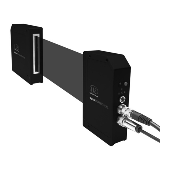
TRIGGER functionality through a PLC. In addition the receiver features a high-speed analog output (0 ... 10 V) with 12-bit digital/analog resolution. 1) ODC1220 series has two digital outputs (OUT0, OUT1) 2) not available for ODC1220 series optoCONTROL 1202 Page 9... - Page 10 Measuring value in tolerance specification Binder series 712 8-pin female connector LED red (-) STATUS DIGITAL OUT0 (connection to transmitter) Binder series 712 LED yellow POWER/Multifunctional display (SPS connector) Fig. 2 Laser micrometer, series optoCONTROL 1202 optoCONTROL 1202 Page 10...
-
Page 11: Technical Data
Technical Data Model optoCONTROL 1202-75 optoCONTROL 1202-100 Measuring range typ. 75 mm typ. 98 mm Distance transmitter - receiver min. 20 mm, max. 2,000 mm Resolution typ. 8 µm Repeatability ≤ ±10 µm Linearity ±0.2 % (±150 µm) ±0.2 % (±196 µm) - Page 12 Model optoCONTROL 1202-75 optoCONTROL 1202-100 LED red (+): Measuring value > upper tolerance threshold LED green: Measuring value lies within tolerance threshold LED-indication LED red (-): Measuring value < lower tolerance threshold LED yellow: multifunction Protection class electronics: IP 54, optics: IP 67...
-
Page 13: Delivery
1 Instruction manual 1 Receivcer ODC1202-x-R 1 Software manual 1 Product CD In case of damage or missing parts, please contact Micro-Epsilon Eltrotec or the supplier. Storage - Storage temperature: -20 to +85 °C (-4 to +185 °F) - Humidity:... -
Page 14: Installation And Mounting
Installation and Mounting The measurement system optoCONTROL 1202 is an optical system for measurements with µm accuracy. Make sure it is handled carefully when installing and operating. Sensor Mounting Mount the sensor only to the existing holes on a flat surface. Clamps of any kind are not permitted. - Page 15 Recommended tightening torque -> max. +10 % valid, min. -20 % do not fall below The tightening torques named in the table are recommended values and can vary according to each case of application. Basis of consideration: µ =0.12 optoCONTROL 1202 Page 15...
- Page 16 The optional available mounting rail for fixing of transmitter and receiver allows operating distances up to 2,000 mm. Fix the mounting rail so that it is not bended respectively twisted. Minimum distance between transmitter and receiver: 20 mm Maximum distance between transmitter and receiver: 2,000 mm optoCONTROL 1202 Page 16...
- Page 17 20 (0.79) 130 (5.12) 20 (0.79) 75 (2.95) (3.14) (0.70) (0.74) (1.57) M5 - 8 deep M5 - 8 deep (1,57) (3.14) (0.39) (1.38) Fig. 4 Dimensional drawing optoCONTROL 1202-75, dimensions in mm (inches), not to scale optoCONTROL 1202 Page 17...
- Page 18 20 (0.79) 75 (2.95) (0.79) 20 (0.79) (0.74) (3.14) (1.57) (1.97) M5 - 8 deep M5 - 8 deep (1.18) (2.76) (1.38) (0.39) Fig. 5 Dimensional drawing, optoCONTROL 1202-100, dimensions in mm (inches), not to scale optoCONTROL 1202 Page 18...
-
Page 19: Electrical Connections
7-pin female connector 8-pin female connector 3-pin. female connector Binder, series 712 Binder, series 712 Binder, series 712 (connector for ME service) (power supply, (connection to transmitter) output) Fig. 6 Electrical connections of transmitter and receiver optoCONTROL 1202 Page 19... - Page 20 Fig. 7 Typical wiring of transmitter, receiver, control the digital input IN1 and the digital output OUT0 Bending radii cables: SCD1202-x / SCA1202-x / CE1202-x: minimal 80 mm flexible or 53 mm fixed 1) High side/low side switch. Drives the load in direction to power supply or to ground. optoCONTROL 1202 Page 20...
-
Page 21: Power Supply, Inputs And Outputs
When a HIGH-pulse is applied at the digital input INO, the external triggering (measuring value output) is set at the hardware. RESET-Function, IN1 When a HIGH-pulse of less than 750 ms duration is applied, the RESET function is performed at the receiver. This resets the current maximum and minimum values. optoCONTROL 1202 Page 21... - Page 22 The polarity of the digital outputs can only be changed via the parameter „POLARITY“ in the software tool: - POLARITY > DIRECT: Activated digital output is on +UB (+15 VDC ... +30 VDC), - POLARITY > INVERSE: Activated digital output is on 0 V level. optoCONTROL 1202 Page 22...
-
Page 23: Serial Interface
53 mm (fixed), 80 mm (flexible). Assignment 4-pin. 9-pin. Sub-D Power supply Ground (0 V) View on solder side male cable connector Fig. 9 Pin assignment for 4-pin. male connector respectively SCD1202-x for connection to a PC optoCONTROL 1202 Page 23... -
Page 24: Operation
Measuring value > upper tolerance limit (output OUT1) Fig. 10 Control and display elements at the receiver There are no display elements located at the transmitter. The selection of mode, the video threshold et cetera is effected with the software tool exclusively. optoCONTROL 1202 Page 24... -
Page 25: Evaluation Mode
(for width and gap) in the intensity profile of the CCD is evaluated. CENTER: The mean value of the first and second edge is used as measure- ment value: CENTER = (R-EDGE+L-EDGE)/2 optoCONTROL 1202 Page 25... -
Page 26: Analog Output
If the light curtain is fully cov- 10 V ered by a target the receiver Receiver completely outputs a signal of 10 V. blocked Fig. 11 Analog signal behaviour with different target positions optoCONTROL 1202 Page 26... -
Page 27: Limit Monitoring, Digital Outputs
ƒ tolerance potentiometer, see Chap. 6.1, in the software tool via the parameter ƒ “Teach“ and ƒ “TOLERANCE-VALUE“, see software description. Time [s] Fig. 12 Switching behaviour of the digital outputs, output polarity (POLARITY) = DIRECT optoCONTROL 1202 Page 27... -
Page 28: External Triggering, In0
The example in Fig. 13 requires a TRIG-MODE „EXT. INO HIGH“ (Trigger Mode) and a ANA-OUT „MAXIMA“ (Analog Output Mode). The trigger mode EXT IN0 L/H provides the actual measuring value with the rising edge at analog output. optoCONTROL 1202 Page 28... -
Page 29: Reset Function, In1
Fig. 14 Pulse duration at digital input IN1 decides about Reset- or Teach function On: Visualization operating voltage 1 x shortly blinking: Reset- max/min function 3 x shortly blinking: Teach function Fig. 15 Yellow multifunction LED on the receiver optoCONTROL 1202 Page 29... -
Page 30: Software Tool
Software Tool The ODC1202 tool software is used for parameterizing and controlling the optoCONTROL 1202. The measured values provided by the receiver can be visualized with the PC software. The software provides you among other things - at the adjustment of transmitter and receiver - at setting of suitable tolerance limits. -
Page 31: Sensor Mounting With Video Signal
Fig. 16 Intensity distribution on receiver at optimal mounting of transmitter and receiver A detailed description of the transmitter mounting with the support of the video signal you will find as file on the provided CD-ROM. optoCONTROL 1202 Page 31... -
Page 32: Calibration
In the unlikely event that errors should occur despite our thorough quality control, this should be reported immediately to MICRO-EPSILON Eltrotec. The warranty period lasts 12 months following the day of shipment. Defective parts, except wear parts, will be repaired or replaced free of charge within this period if you return the device free of cost to MICRO-EPSILON Eltrotec. -
Page 33: Decommissioning, Disposal
Mounting rail for ODC1202, 500 mm; distance light source/receiver max. 200 mm ODC1202-L500 Mounting rail for ODC1202, 800 mm; distance light source/receiver max. 500 mm EK1100/CSP2008 Bus terminal EL3162/CSP2008 Bus terminal; 2-channel analog input terminal CSP2008 Universal controller for displacement sensors Further length are available on demand. optoCONTROL 1202 Page 33... -
Page 34: Factory Setting
Factory Setting Mode: L-Edge Average number: 2 values optoCONTROL 1202 Page 34... - Page 36 MICRO-EPSILON Eltrotec GmbH X9751200-A051069SWE Manfred-Wörner-Straße 101 · 73037 Göppingen / Germany MICRO-EPSILON MESSTECHNIK Tel. +49 (0) 7161 / 98872-300 · Fax +49 (0) 7161 / 98872-303 *X9751200-A05* eltrotec@micro-epsilon.de · www.micro-epsilon.com...
Need help?
Do you have a question about the optoCONTROL 1202 and is the answer not in the manual?
Questions and answers