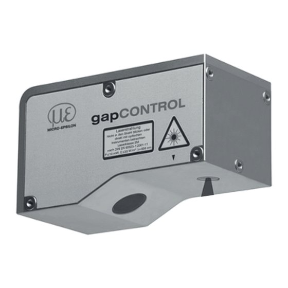
Advertisement
1.
Warnings
Connect the power supply and the display-/output device in accordance with the
safety regulations for electrical equipment. The power supply must not exceed the
specified limits.
> Danger of injury, damage or destruction of the sensor
Avoid shock and vibration to the sensor. Avoid continuous exposure to dust and spray
on the sensor. Avoid exposure to aggressive materials (e. g. washing agent, penetrat-
ing liquids or similar) on the sensor.
> Damage to or destruction of the sensor
Read the detailed instruction manual before operating the sensor. You will find this
manual on the provided CD or online at www.micro-epsilon.com.
2.
Notes on CE Marking
The following apply to the gapCONTROL 27xx:
- EU directive 2014/30/EU
- EU directive 2011/65/EU, „RoHS" category 9
The sensor fulfills the specifications of the EMC requirements, if the instructions in the
manual are followed.
3.
Proper Environment
- Protection class:
- Operating temperature: 0 to +50 °C (+32 to +122 °F), by free circulation of air
- Storage temperature:
- Humidity:
- Vibration:
- Mechanical shock:
4.
Scope of Delivery of gapCONTROL 27xx
- 1 Sensor gapCONTROL 27xx with integrated controller
- 1 power supply cable PC2700-4,5, length 4,5 m; ODU round connector and free
cable ends
- 1 gapCONTROL Setup Software CD with documentations
- 1 Sensor inspection log / assembly instructions
- 1 Bag of accessories with one ODU male connector 6-pin (RS 422) and two
protective caps for ODU female connector (6- or 8-pin)
Assembly Instructions
gapCONTROL
IP 65 (Only applies to connected output plugs or
protective caps)
-20 to +70 °C ( -4 to +158 °F)
5 - 95 % (non condensing)
DIN EN 600068-2-6 (sine shaped)
DIN EN 60068-2-29
2711/2761 (500)
Advertisement
Table of Contents

Summary of Contents for MICRO-EPSILON gapCONTROL 2711
-
Page 1: Assembly Instructions
> Damage to or destruction of the sensor Read the detailed instruction manual before operating the sensor. You will find this manual on the provided CD or online at www.micro-epsilon.com. Notes on CE Marking The following apply to the gapCONTROL 27xx: - EU directive 2014/30/EU - EU directive 2011/65/EU, „RoHS“... -
Page 2: Laser Safety
Laser Safety The gapCONTROL 27xx sensors operate with a semiconductor laser having a wave- length of 660 nm (visible/red). The laser operation is indicated visually by the LED on the sensor. gapCONTROL 27xx sensors with a maximum laser power up to 10 mW are classified in Laser Class 2M (IIM). -
Page 3: Led Displays
Connections, LED Displays laser on state 1394/ Ethernet 1394/Ethernet 24 VDC RS 422 RS 422 24 VDC LLT27xx, top side LLT27xx (501), rear side The sensors are available in two versions: Sockets on the top side or on the rear side. LED displays LED „laser on“... -
Page 4: Further Information
- RS422: Loading of programs and transmitting of measurement results. - Synchronization/Triggering: Synchronization resp. triggering using switching signals. 1) Optional RS422 interface cable (SC2700-4,5RS422) from Micro-Epsilon, compati- ble to the RS422 to USB converter. All outputs or inputs are designed symmetrically. Internal terminating resistors 120 Ohm. - Page 5 Ethernet connection, standard link to the PC RJ45 connector 8-pin. connector The pin numbers Pin no. Color stranded Pin no. 10BaseT, 1000BaseT refer to the hook-up wire 100BaseTX gapCON- white (orange) TROL 27xx unit. orange Micro-Ep- white (green) silon blue recom- white (blue) mends...
- Page 6 gapCONTROL 27xx with scanCONTROL Output Unit Status voltage supply 13 14 - Power jumper contacts LINK ETHERNET ACT 1 - System LINK Data contacts Ñ System supply (out) 0: WBM 24 V 255: DHCP Supply via power jumper contacts 24 V System supply (In) 24 V 750-626...
- Page 7 for Connection to an SPS Status 13 14 Status 13 14 DO 2 DO 1 Function Error DO 8 DO 7 Data A1 A2 A1 A2 Data contacts contacts DO 2 DO 1 AO 1 AO 2 A3 A4 D0 4 DO 3 A5 A6 A3 A4...
- Page 8 Now you can operate the gapCONTROL measurement system with the gapCONTROL Setup Software. No driver is required for sensors with an Ethernet interface. www.micro-epsilon.com MICRO-EPSILON Messtechnik GmbH & Co. KG Königbacher Str. 15 94496 Ortenburg / Germany, Tel. +49 (0) 85 42/1 68-0 *X9771247.002-A06*...


Need help?
Do you have a question about the gapCONTROL 2711 and is the answer not in the manual?
Questions and answers