Table of Contents
Advertisement
Quick Links
ODC 2600-40
ODC 2600-40(209)
MICRO-EPSILON Eltrotec GmbH
Manfred-Wörner-Straße 101 · 73037 Göppingen / Germany
Tel. +49 (0) 7161 / 98872-300 · Fax +49 (0) 7161 / 98872-303
eltrotec@micro-epsilon.com · www.micro-epsilon.com
Your local contact:
www.micro-epsilon.com/contact/worldwide/
Operating Instructions
optoCONTROL
2600
Advertisement
Table of Contents

Subscribe to Our Youtube Channel
Related Manuals for MICRO-EPSILON optoCONTROL 2600


Summary of Contents for MICRO-EPSILON optoCONTROL 2600
- Page 1 Operating Instructions optoCONTROL 2600 ODC 2600-40 ODC 2600-40(209) MICRO-EPSILON Eltrotec GmbH Manfred-Wörner-Straße 101 · 73037 Göppingen / Germany Tel. +49 (0) 7161 / 98872-300 · Fax +49 (0) 7161 / 98872-303 eltrotec@micro-epsilon.com · www.micro-epsilon.com Your local contact: www.micro-epsilon.com/contact/worldwide/...
- Page 2 Laser micrometer MICRO-EPSILON Eltrotec GmbH Manfred-Wörner-Straße 101 73037 Göppingen / Germany Tel. +49 (0) 7161 / 98872-300 Fax +49 (0) 7161 / 98872-303 eltrotec@micro-epsilon.com www.micro-epsilon.com...
-
Page 3: Table Of Contents
Read out min/max Values Followed by Reset ............47 6.6.3.9 Read Option Data ......................48 6.6.3.10 Write Option Data ......................48 6.6.3.11 Save Option Data ......................50 6.6.3.12 Read Measurement Program Data ................51 6.6.3.13 Write Measurement Program Data ................52 optoCONTROL 2600... - Page 4 A 5.4 Options (Interface) ............................73 A 5.5 Selecting the Measurement Program ......................75 A 5.6 Editing the Measurement Program ....................... 76 A 5.7 Limits with the Multi-segment Measurement ....................79 Standard Measurement Program Data for ODC2600-40 ............80 optoCONTROL 2600...
-
Page 5: Safety
> Damage to or destruction of the light source/receiver or the controller Notes on CE Marking The following apply to the optoCONTROL 2600: - EU Directive 2014/30/EU - EU Directive 2011/65/EU Products which carry the CE mark satisfy the requirements of the EU directives cited and the relevant applicable harmonized European standards (EN). -
Page 6: Intended Use
Measure Intended Use - The optoCONTROL 2600 is designed for use in industrial and laboratory applications. It is used for ƒ measuring displacement, distance, edge and offset ƒ edge crack testing ƒ position acquisition of components or machine parts - The system must only be operated within the limits specified in the technical data, see 3.5. -
Page 7: Light Source
Measure Light Source The light source of the optoCONTROL 2600 is a high performance red LED. LED light sources are not classified according to the laser standard. On the controller a yellow LED (“Light On”) signals by its illumination that radiation is being emitted from the optical opening of the light source. -
Page 8: Functional Principle, Technical Data
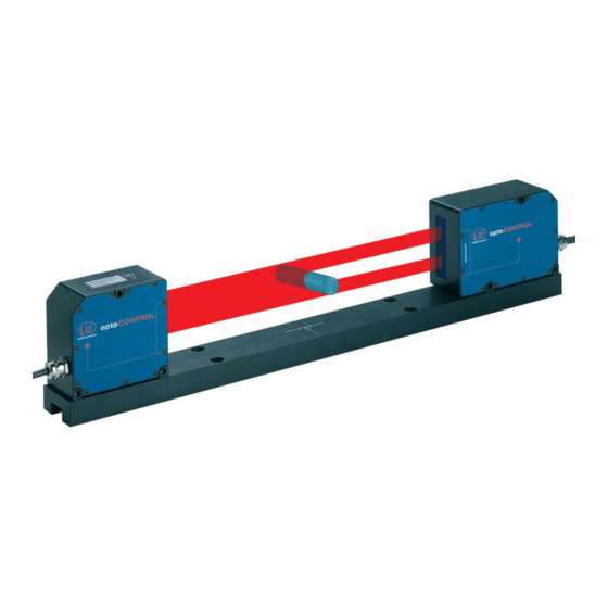
The sensor unit is controlled and evaluated by an intelligent controller with graphical display for operation and measurement indication. The data obtained with the various selectable measurement programs is output via ana- log and digital interfaces. Fig. 2 Measurement system ODC2600-40, complete optoCONTROL 2600 Page 8... -
Page 9: Controller
(S1 or S2). LED red lights Error LED yellow lights Measurement operation, Light ON Menu operation, Light ON LED grün lights System in operation Fig. 4 LEDs on the front panel of the controller optoCONTROL 2600 Page 9... -
Page 10: Rear View Of The Controller
For each measurement program 2 limits and 2 warning levels can be programmed. For the Multi-segment program only 2 limits per segment 1 and segment 2 can be pro- grammed. Potentially measured segments 3 and 4 are not monitored. Application-specific measurement programs can also be generated by menu. optoCONTROL 2600 Page 10... -
Page 11: Technical Data
2) Measured with 3 sigma; edge measurement without averaging, working distance 150±5 mm, option 209: 200 mm ± 5 mm 3) Measured with static noise over 3 min. 4) Only for synchronization of two or more optoCONTROL 2600 models optoCONTROL 2600 Page 11... -
Page 12: Block Diagram
If two or more optoCONTROL 2600s are operated on the same target, they can be synchronized to one another, see 6.5. As master, controller 1 then synchronizes controller 2. All synchronization signals are electrically isolated by optocouplers. optoCONTROL 2600 Page 12... -
Page 13: Error Output
A very high edge detection threshold will require a dynamic curved edge detection threshold. This can be set by activating the 1B20 – Set light referencing tun- ing menu item. Dynamic edge detection threshold: 50 % Fig. 9 Video image with dynamic edge detection threshold optoCONTROL 2600 Page 13... -
Page 14: Delivery
If there is damage or parts are missing, immediately contact the manufacturer or supplier. Storage - Temperature range (storage): -20 ... +70 °C (-4 ... +158 °F) - Humidity: 5 - 95 % RH (non-condensing) optoCONTROL 2600 Page 14... -
Page 15: Installation And Mounting
35 mm (1.38) fixed: 23 (.91) Receiver flexible: 49 mm (1.93) fixed: 33 (1.30) Fig. 12 Mounted sensor unit with controller The light source and receiver are screwed and pinned to the mounting rail and can be removed. optoCONTROL 2600 Page 15... - Page 16 (.31 dia.) 3 K7 (.1) 4.5 (.18 dia.) 6.6 (.26 dia.) 45 (1.77) 40 (1.57) 37.5 (1.48) 26.5 (1.04) 22.5 (.89) 7.5 (.30) 5 (.20) Fig. 14 Dimensional drawing of the mounting rail Dimensions in mm (inches) optoCONTROL 2600 Page 16...
- Page 17 Offset: Maximum 0.5 mm Tilt: Maximum 0.25 ° Fig. 16 Permissible adjustment error Connect light source and receiver with the controller. Use the video signal, see 6.3.4, for accurate adjustment of the light source and receiver. optoCONTROL 2600 Page 17...
-
Page 18: Mounting The Controller
The light source and receiver are assigned to their particular controller through the serial number and must not to be endangered. Minimum cable bending radius Signal output cable SCA2500 respectively SCD2500 Flexible: 96 mm Fixed: 40 mm optoCONTROL 2600 Page 18... -
Page 19: Power Supply
Route the analog connecting cable according to the general applicable rules in mea- surement engineering, i.e. for example, not directly next to pulse-loaded lines, best in a separate cable duct. optoCONTROL 2600 Page 19... - Page 20 13 Analog output (Signal) Analog signal (voltage) green Fig. 19 Sub-D connector, 25-pole 1) For SCD2500-3/10/RS422 only 2) For SCD2500-3/3/RS232 only 3) In trigger mode used as reset input 4) In trigger mode used as trigger input optoCONTROL 2600 Page 20...
-
Page 21: Switching Outputs
Press the ESC key to abort the sequence without saving. Then the outputs are deactivated. Error[ X]: active UW[ ]: not active OW[ ]: not active UT[ X]: active OT[ X]: active Fig. 22 Test of the switching outputs optoCONTROL 2600 Page 21... -
Page 22: Switching Inputs
= 53.3 Ohm, also 56 Ohm All GND signals are connected together internally and with the minus pole (GND) of the 24 V supply voltage. Controller High 0.8 V Fig. 24 Circuit synchronal signal input, 25-pol. Sub-D optoCONTROL 2600 Page 22... -
Page 23: Operation
Select segments (only for segment and multiseg- ment measurement programs) Offset / gain, separately for display and analog output Upper tolerance limit / lower tolerance limit Upper warning level / lower warning level Median Averaging Measurement mode optoCONTROL 2600 Page 23... -
Page 24: Operation
The operator can decide only on leaving the main menu whether the parameters are to be stored or not. Then the data is retained even after the supply voltage is switched on again. optoCONTROL 2600 Page 24... -
Page 25: Adjustment With The Video Signal
If no changes are made at all, then no query for saving is presented on quitting the main menu. The currently set parameters appear first during selection in the individual menus. optoCONTROL 2600 Page 25... -
Page 26: Select Measurement Program
Edge 4 (dark - bright) Edge 3 (bright - dark) Edge 2 (dark - bright) Edge 1 (bright - dark) (Start of scan - zero) Fig. 28 Definition of terms for measurement programs segment, gap, diameter and width optoCONTROL 2600 Page 26... - Page 27 2. Segment 1. Segment Multi-segment: (MULTISEG) Measurement of up to 4 selectable segments. Serial 3. Segment output of measurements via the digital output. No analog output! 4. Segment Fig. 29 Measurement programs (standard programs) optoCONTROL 2600 Page 27...
-
Page 28: Edit Measurement Program (User-Specific Programs)
Select program. After saving (or responding negatively with ESC), you are again returned to the measure- ment mode. The measurement program name appears in the measurement display mode Full Display for checking in the display. optoCONTROL 2600 Page 28... -
Page 29: Zero-Setting Function
(all changes) and must now save a user-specific program with name. For stable measurements observe a warm-up period of 30 minutes. Different offset values for the display and the analog output can be entered via the menu function. optoCONTROL 2600 Page 29... -
Page 30: Mastering
In the Multi-segment measurement program the analog output remains switched off at 0 V. Up to 80 edges on the measurement object can be used to program the segments. Use the command SWITCH EDGE (see page 43) to change between the segments. optoCONTROL 2600 Page 30... -
Page 31: Display Scaling
Display offset: +0,0110 mm The menu points Enter offset and Enter gain are not available in the Multi-segment measurement program. The settings Offset and Gain for the display or the analog output have no effect on the digital value. optoCONTROL 2600 Page 31... -
Page 32: Limit Monitoring
Any additionally set averaging occurs after the median filter. The setting of the filter sizes 3, 5, 7 or 9 and switching off the filter are described in Chap- ter Editing the Measurement Program, see A 5.6. optoCONTROL 2600 Page 32... -
Page 33: Measurement Modes
Output of the momentary value SC1 TRIG triggered valid at the time of the trigger pulse. The value is held on the output until the next trigger pulse or reset pulse. Fig. 32 Measurement modes of the optoCONTROL 2600-40 optoCONTROL 2600 Page 33... - Page 34 Measurement 3D00: Select measurement mode NORMAL program Fig. 34 Settings for the measurement mode selection If the optoCONTROL 2600 is in the trigger mode, then the light source cannot be switched off! Continuously measured and held peak value Measurement Internal measurement Processing time approx.
- Page 35 Error Internal measurment Processing time Trigger input approx. 1 ms Reset input Meas Meas 2.3 kHz Meas 2.3 kHz Digital / serial 2.3 kHz 2.5 ms Fig. 37 Measurement mode, example Momantary value triggered optoCONTROL 2600 Page 35...
-
Page 36: Analog Output
> 20 mm is limited to 10.02 V. With x > 40,..mm the error value of 10.04 V then ap- pears. If negative output voltages disturb, an analog offset of -20 mV (-0.020 V) can be entered. Error With in the standard setting, a voltage of +10.04 V is output. optoCONTROL 2600 Page 36... -
Page 37: Error Handling
Inputs and outputs on the 25-pol. Sub-D connector Fig. 39 Synchronization of controllers The synchronizing signal of the optoCONTROL 2600 has the double frequency of the measuring rate. I.e. pictures from the CCD array are read in twice and than are averaged. - Page 38 Picture 2 SYNCOUT Slave 4.600 Hz Picture 1/2 Picture 2/1 approx. 12 µs Fig. 40 Time offset through synchronizing signal Internal cycle signal Synchron OUT Data Fig. 41 Time response controller Integration Reading Computation Controlling Output optoCONTROL 2600 Page 38...
-
Page 39: Digital Interfaces
Figure Figure 0x09 Figure Figure Figure Figure Figure 0x0D 3. segment <Tab> 4. segment <CR> The measured values are separated with a tab character (0x09). Finally a <CR> („carriage return“, 0D) is attached to the string. optoCONTROL 2600 Page 39... - Page 40 Max. number of edges 65528 Invalid measuring program 65529 Segment 1st edge > 2nd edge 65530 Segment number of edges < last edge 65531 Invalid working distance 65533 Laser off 65534 Invalid float 65535 DMA setup error optoCONTROL 2600 Page 40...
-
Page 41: Control Commands
ODC2500 sends a length figure corresponding to the number of 32-bit words in the complete data packet. Consequently, the following 32-bit word must be transmitted sequentially over the inter- face: 0x11 0x20 0x00 0x00 Byte-by-byte reading and out from left to right! optoCONTROL 2600 Page 41... - Page 42 RESET_LIGHT_REFERENCE_TUNING Activates a fixed threshold val- ue for dark/light transition 0x00002033 RD MINMAX Read out the min/max values 0x00002034 RD MINMAX RESET Read out the min/max values with reset Fig. 48 Overview of the optoCONTROL 2600 commands optoCONTROL 2600 Page 42...
-
Page 43: Information Command
„1“ 0x3143444F 0x22 0x20 0x00 0x00 0x00002022 Response: Byte 1 Byte 2 Byte 3 Byte 4 Remark „0“ „D“ „C“ „1“ 0x3143444F 0x22 0xA0 0x03 0x00 0x0003A022 Without error 0x00 0x00 0x00 0x00 0x00000000 Error code optoCONTROL 2600 Page 43... -
Page 44: Stop Command
„1“ 0x3143444F 0x01 0x20 0x00 0x00 0x00002001 Response: Byte 1 Byte 2 Byte 3 Byte 4 Remark „0“ „D“ „C“ „1“ 0x3143444F 0x01 0xA0 0x02 0x00 0x0002A001 Without error 0x00 0x00 0x00 0x00 0x00000000 Error code optoCONTROL 2600 Page 44... -
Page 45: Change The Measurement Program
7 ... USER2 8 ... USER3 9 ... USER4 Response: Byte 1 Byte 2 Byte 3 Byte 4 Remark „0“ „D“ „C“ „1“ 0x3143444F 0x23 0xA0 0x03 0x00 0x0003A023 Without error 0x00 0x00 0x00 0x00 0x00000000 Error code optoCONTROL 2600 Page 45... -
Page 46: Change Edges (Segment And Multi-Segment Programs)
0x33 0xA0 0x04 0x00 0x0004A033 Without error 0x33 0xE0 0x03 0x00 0x0003E033 Error + 4 bytes error code Min [0...65519]: Binär - 0x00008B3E Max [0...65519]: Binär - 0x00008B4B Min/Max[mm] Min/Max[0...65519] * 40.824 / 65519 - 0.4204872 optoCONTROL 2600 Page 46... -
Page 47: Read Out Min/Max Values Followed By Reset
0x34 0xA0 0x04 0x00 0x0004A034 Without error 0x34 0xE0 0x03 0x00 0x0003E034 Error + 4 bytes error code Min [0...65519]: Binär - 0x00008B3E Max [0...65519]: Binär - 0x00008B4B Min/Max[mm] Min/Max[0...65519] * 40.824 / 65519 - 0.4204872 optoCONTROL 2600 Page 47... -
Page 48: Read Option Data
If incorrect data is found or a different error arises, the data is not accepted into the main memory. Command: Byte 1 Byte 2 Byte 3 Byte 4 „+“ „+“ „+“ 0x0D 0x0D2B2B2B „0“ „D“ „C“ „1“ 0x3143444F 0x27 0x20 0x0B 0x00 0x000B2027 optoCONTROL 2600 Page 48... - Page 49 1, 2 unsigned short RS232 Timeout transmis- Binary No effect sion unsigned The factory data is accepted. short RS232 Timeout Binary No effect receipt unsigned The factory data is accepted. short Fig. 49 Option data record optoCONTROL 2600 Page 49...
-
Page 50: 6.6.3.11 Save Option Data
Response: Byte 1 Byte 2 Byte 3 Byte 4 Remark „0“ „D“ „C“ „1“ 0x3143444F 0x29 0xA0 0x03 0x00 0x0003A029 Without error 0x00 0x00 0x00 0x00 0x00000000 Error code Possible error coder: 0x00000006 Flash access error optoCONTROL 2600 Page 50... -
Page 51: 6.6.3.12 Read Measurement Program Data
Binary - 0x0000 Rear edge for Segment Binary - 0x0000 Reserve 7 Binary - 0x0000 Reserve 8 Binary - 0x0000 Place-holder Binary - 0x0000...0xFFFF Master value Binary - 0x00000000 0,0 mm Fig. 50 Measurement program data optoCONTROL 2600 Page 51... -
Page 52: 6.6.3.13 Write Measurement Program Data
0, 1, 2, 3, 4, 0... NORMAL unsigned 5, 6, 7 1 ... MAX CONT short 2 ... MIN CONT 3 ... P-P CONT 4 ... MAX TRIG 5 ... MIN TRIG 6 ... P-P TRIG 7 ... SC1 TRIG optoCONTROL 2600 Page 52... - Page 53 0 ... 80 short Reserve Binary unsigned short Place-holder Binary No effect. The factory data are accept- unsigned short Master value Binary -40.000 ... Entry is made in mm float +40.000 Fig. 51 Measurement program data record optoCONTROL 2600 Page 53...
-
Page 54: 6.6.3.14 Save Measurement Program Data
This command corresponds to the external reset input in the Trigger measurement mode. Response: Byte 1 Byte 2 Byte 3 Byte 4 Remark „0“ „D“ „C“ „1“ 0x3143444F 0x2B 0xA0 0x03 0x00 0x0003A02B Without error 0x00 0x00 0x00 0x00 0x00000000 Error code optoCONTROL 2600 Page 54... -
Page 55: 6.6.3.16 Activating The Output In The Trigger Measurement Mode
Byte 2 Byte 3 Byte 4 Remark „0“ „D“ „C“ „1“ 0x3143444F 0x2D 0xA0 0x03 0x00 0x0003A02D Without error 0x00 0x00 0x00 0x00 0x00000000 Error code Possible errors: 0x0000000D Unsuccessful Light reference tuning, optical path not free optoCONTROL 2600 Page 55... -
Page 56: 6.6.3.18 Reset The Light Reference Tuning
Error length, stated length in the parameter > buffer size receiver 0x05 Not used 0x07 Error erase flash 0x08 Error flash sector, during writing or deletion of the flash 0x09 Error video, video can not be fetched by the DSP optoCONTROL 2600 Page 56... -
Page 57: Timing
One output cycle is added for each segment in Multi-segment mode. This reduces the measuring rate. Cycle Time (µs) Integration (measurement) Reading in Computation 1305 Controlling 1740 Output 2175 Fig. 52 Internal cycles in the ODC controller optoCONTROL 2600 Page 57... -
Page 58: Error Effects
The direct irradiation from primary light sources, such as for example, reflector lamps or sunlight, onto the receiver and the target should be avoided. Avoid direct irradiation of ambient light in the receiving area. NOTICE > Measurement error or measurement is not possible optoCONTROL 2600 Page 58... -
Page 59: Contamination
6.8.4 Transparent Target Objects With application on transparent materials (e.g. edges of clear films and plates or transparent round material - glass tubes), MICRO-EPSILON Eltrotec GmbH recom- mends that tests are first carried out. Use the menu Video, see A 5.3 It is likely that transparent target objects (e.g. -
Page 60: Reduced Light Intensity
Repeat the adjustment several times until the video curve shows the desired result. Confirm and save your settings with If you confirm your settings with ESC, the light intensity is volatile and will be lost, if you power down the system. optoCONTROL 2600 Page 60... -
Page 61: Show Software Version
It is not permitted to make unauthorized structural and / or technical modifications or alterations to the product. In the interest of further development, MICRO-EPSILON reserves the right to modify the design. In addition, the General Terms of Business of MICRO-EPSILON shall apply, which can be accessed under Legal details | Micro-Epsilon https://www.micro-epsilon.com/impres-... -
Page 62: Appendix
Appendix | Optional Accessories Appendix Optional Accessories The following accessory parts are optionally available for the optoCONTROL 2600 from MICRO-EPSILON Eltrotec GmbH: Name Description Item number PS2020 Power supply 24 V Input 100 - 240 VAC; output 24 2420062 VDC / 3.3 A, installation type;... -
Page 63: A 2 Factory Setting
Unit measurement display Analog output and display for Error error RS232 Baudrate 115.200 Parity none Stop bits External switching of the light not active source 2000 Measurement program after Power ON Standard edge bright - dark optoCONTROL 2600 Page 63... -
Page 64: Other Pin Assignments
Optocoupler input (-) brown Sync signal input (+) Optocoupler input (+) red-blue Analog output (Signal) Signal (voltage) green (inside) Analog output (AGND) Potential (AGND) Inner shield Fig. 56 Pin assignment, optional SCA2500-x(01) signal and output cable optoCONTROL 2600 Page 64... -
Page 65: Cable For Rs232 And Rs422
RS422 reception (negat- RS422 reception (posi- tive) RS422 transmission (positive) RS422 transmission (inverted) Analog output (AGND) black (inner conductor) Analog output (signal) green black (outer screen on connector housing 25-pin) Fig. 58 Pin assignment SCD2500-x/3/RS422 optoCONTROL 2600 Page 65... -
Page 66: A 3.3 Interface Card If2008/Pcie
IF2008/PCIE interface card. The designations Sensor 1 and 3 refer to the terminology of the MEDAQlib, see A driver software and the ICONNECT data acquisition software from MICRO-EPSILON Eltro- tec GmbH. For further information, please refer to the documentation about IF2008/PCIE, ICONNECT and MEDAQlib from MICRO-EPSILON Eltrotec GmbH. - Page 67 RS422 transmission (positive) RS422 transmission (negated) Sync signal input (+) Sync signal input (-) Analog output (AGND) black (inner conductor) Analog output (signal) green black (outer shield on 25-pin housing) Fig. 63 Pin assignment SCD2500-x/IF2008 (15-pin) optoCONTROL 2600 Page 67...
-
Page 68: Software Support With Medaqlib
- works independent of the used interface type, - features by identical functions for the communication (commands), - provides a consistent transmission format for all MICRO-EPSILON Eltrotec GmbH sensors. For C/C++ programmers MEDAQLib contains an additional header file and a library file. -
Page 69: A 5 Operating Menu
+0.0083 +11.5582 +11.5665 +0.0025 +13.2331 +13.2356 Press briefly Press for 3 seconds Reset 1st switching: "Main menu" Min, Max, P-P Temporary mastering/zero-setting 2nd switching: Undo of mastering/zero-setting Fig. 64 Operating Menu Initialization and Operation in the Measurement Mode optoCONTROL 2600 Page 69... -
Page 70: A 5.2 Dialog And Procedure For Saving
(this data is present at Pow er On) (this data is present at Pow er On) Software reset Fig. 65 Operating Menu Dialog and Procedure for Saving optoCONTROL 2600 Page 70... -
Page 71: A 5.3 Options (General Settings)
+10,04 V DC Error is output select RS232 parameter select RS422 parameter Fig. 66 Operating Menu Options (General Settings) optoCONTROL 2600 Page 71... - Page 72 Attention! the light source activ measuring mode NORMAL Clear data! Are you sure? clear user data options + program Yes=ENTER No=ESC video service menu Fig. 67 Operating Menu Options (General Settings), part 2 optoCONTROL 2600 Page 72...
-
Page 73: A 5.4 Options (Interface)
The user can decide only on quitting the main menu whether the parameters are to be written into the flash memory. The data is then also present after Power ON. The option data located in the main memory is used for the measurement mode. The currently set parameter appears first during selection. optoCONTROL 2600 Page 73... - Page 74 70 % Only activation Error[ X]: active Test UW[ ]: not active with temporary OW[ ]: not active switching output UT[ X]: active OT[ X]: active Fig. 69 Operating Menu Options (Interface), part 2 optoCONTROL 2600 Page 74...
-
Page 75: A 5.5 Selecting The Measurement Program
The option data located in the main memory is used for the measurement mode. The currently set parameter appears first during selection. A maximum of four user programs can be saved. They can be overwritten. The factory setting for the measurement program is the standard light-dark edge. Measurement program: 2100 Program name: EDGEHL optoCONTROL 2600 Page 75... -
Page 76: A 5.6 Editing The Measurement Program
The function zero-setting / mastering cannot be executed. 2) The limit output of the Multi-segment measurement program differs from the other standard programs. For the segment 1 + 2 one upper and one lower limit can be defined. optoCONTROL 2600 Page 76... - Page 77 The measuring mode cannot be voted for respect, if light control is active. Measuring mode = NORMAL 2) The limit output of the Multi-segment measurement program differs from the other standard programs. For the segment 1 + 2 one upper and one lower limit can be defined. optoCONTROL 2600 Page 77...
- Page 78 ? Fig. 73 Operating menu Editing the Measurement Program, part 3 The leading edge can also be set = 0; then the measurement is taken from the zero point of the receiver. optoCONTROL 2600 Page 78...
-
Page 79: Limits With The Multi-Segment Measurement
1.segment (LW) low limit +000.0000 mm high limit S2 enter 2.segment (HL) high limit +040.0000 mm low limit S2 enter 2.segment (LL) low limit +000.0000 mm Fig. 74 Operating menu Limits with the Multi-segment Measurement optoCONTROL 2600 Page 79... -
Page 80: A 6 Standard Measurement Program Data For Odc2600-40
+000 0000 +000 0000 +000 0000 +000 0000 +000 0000 +000 0000 limit (lower WL 2nd segment) Median None None None None None None No of measurements for average Measurement mode NORMAL NORMAL NORMAL NORMAL NORMAL NORMAL optoCONTROL 2600 Page 80... - Page 82 MICRO-EPSILON Eltrotec GmbH Manfred-Wörner-Straße 101 · 73037 Göppingen / Germany Tel. +49 (0) 7161 / 98872-300 · Fax +49 (0) 7161 / 98872-303 X9751125-B062101HDR eltrotec@micro-epsilon.com · www.micro-epsilon.com Your local contact: www.micro-epsilon.com/contact/worldwide/ MICRO-EPSILON MESSTECHNIK...
Need help?
Do you have a question about the optoCONTROL 2600 and is the answer not in the manual?
Questions and answers