Table of Contents
Advertisement
Available languages
Available languages
Quick Links
ODC1200
ODC1200/90
MICRO-EPSILON Eltrotec GmbH
ODC1201
Manfred-Wörner-Straße 101 · 73037 Göppingen / Germany
Tel. +49 (0) 7161 / 98872-300 · Fax +49 (0) 7161 / 98872-303
eltrotec@micro-epsilon.com · www.micro-epsilon.com
Your local contact:
Betriebsanleitung
Operating Instructions
optoCONTROL
www.micro-epsilon.com/contact/worldwide/
1200/1201
Advertisement
Chapters
Table of Contents

Related Manuals for MICRO-EPSILON optoCONTROL 1200


Summary of Contents for MICRO-EPSILON optoCONTROL 1200
- Page 1 Betriebsanleitung Operating Instructions optoCONTROL 1200/1201 ODC1200 ODC1200/90 MICRO-EPSILON Eltrotec GmbH ODC1201 Manfred-Wörner-Straße 101 · 73037 Göppingen / Germany Tel. +49 (0) 7161 / 98872-300 · Fax +49 (0) 7161 / 98872-303 eltrotec@micro-epsilon.com · www.micro-epsilon.com Your local contact: www.micro-epsilon.com/contact/worldwide/...
- Page 2 Kompakter Lichtmengensensor Compact light quantity measurement sensor MICRO-EPSILON Eltrotec GmbH Manfred-Wörner-Straße 101 73037 Göppingen / Germany Tel. +49 (0) 7161 / 98872-300 Fax +49 (0) 7161 / 98872-303 e-mail eltrotec@micro-epsilon.com www.micro-epsilon.com...
-
Page 3: Table Of Contents
Elektrische Anschlüsse, Versorgungs- und Ausgangskabel ................ 20 Betrieb............................. 21 Inbetriebnahme .............................. 21 Versorgungsspannung ..........................21 LED‘s, Potentiometer optoCONTROL 1200 ....................22 LED‘s, Potentiometer optoCONTROL 1200/90 ..................... 23 LED‘s, Potentiometer optoCONTROL 1201 ....................24 Ein- und Ausgänge ............................25 Grenzwertausgang ............................27 Analogausgang.............................. - Page 4 Service, Reparatur ......................... 32 Außerbetriebnahme, Entsorgung ..................32 Anhang Optionales Zubehör ....................... 33 IF1032/ETH ..........................35 sensorTOOL Software ......................36 A 3.1 Menü Einstellungen ............................37 A 3.2 Menü Messdatenanzeige ..........................38 A 3.3 Datenaufnahme im sensorTOOL ........................39 optoCONTROL 1200/1201...
-
Page 5: Sicherheit
Vermeiden Sie Stöße und Schläge auf die Lichtquelle / Empfänger. > Beschädigung oder Zerstörung des Sensors Versorgungsspannung darf angegebene Grenzen nicht überschreiten. > Beschädigung oder Zerstörung des Sensors Schützen Sie das Anschlusskabel vor Beschädigung. > Zerstörung des Sensors > Ausfall des Messgerätes optoCONTROL 1200/1201 Seite 5... -
Page 6: Hinweise Zur Ce-Kennzeichnung
- Das System ist so einzusetzen, dass bei Fehlfunktionen oder Totalausfall des Systems keine Personen gefährdet oder Maschinen und andere materielle Güter beschädigt werden. - Bei sicherheitsbezogenener Anwendung sind zusätzlich Vorkehrungen für die Sicherheit und zur Scha- densverhütung zu treffen. optoCONTROL 1200/1201 Seite 6... -
Page 7: Bestimmungsgemäßes Umfeld
Die Schutzklasse ist auf Wasser begrenzt (keine eindringenden Flüssigkeiten oder ähnliches). - Temperaturbereich: ƒ Betrieb: 0 ... +50 °C ƒ Lagerung: -20 ... +70 °C - Luftfeuchtigkeit: 5 ... 90 % (nicht kondensierend) - Umgebungsdruck: Atmosphärendruck optoCONTROL 1200/1201 Seite 7... -
Page 8: Lasersicherheit
Abb. 2 Laserhinweisschild und Laserwarnschild- warnschild, IEC und USA warnschild, deutsch Die Gehäuse von Empfänger und Lichtquelle dürfen nur vom Hersteller geöffnet werden, siehe Für Reparatur und Service sind die Sensoren in jedem Fall an den Hersteller zu senden. optoCONTROL 1200/1201 Seite 8... -
Page 9: Funktionsprinzip, Technische Daten
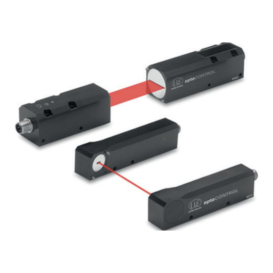
Linse Interferenzfilter Blende Linse Polarisationsfilter Abb. 3 Messprinzip optoCONTROL 1200/1201 Lichtquelle und Empfänger bilden eine Einheit und dürfen nicht getauscht werden. Aufbau eines kompletten Messkanals Das optoCONTROL 120x besteht aus einer Lichtquelle und einer Empfängereinheit. Die gesamte Controlle- relektronik ist im Empfängergehäuse untergebracht und ein zusätzlicher Controller ist nicht nötig. Empfän- ger und Lichtquelle können stufenlos zueinander montiert werden, die 90 °... -
Page 10: Technische Daten
4-pol. Buchse M12 für Stromversorgung, Analog- und Digitalausgang Lichtquelle 4-pol. Buchse M12 für Versorgung und Lasersteuerung Montage Montageschiene, Justageplatten (siehe Zubehör), Montagebohrungen Temperaturbereich Lagerung -20 ... +70 °C Betrieb 0 ... +50 °C Versorgungsspannung 12 ... 32 VDC Maximale Stromaufnahme < 0,3 A optoCONTROL 1200/1201 Seite 10... - Page 11 4) Die angegebenen Werte gelten bei ±2 sigma 5) Gemessen in der Mitte des Messbereiches bei statischem Rauschen über 3 min. 6) Bei direkter oder indirekter Einstrahlung, Abschattung von Tageslicht erhöht die Stabilität der Messung 7) Anschluss über Schnittstellenmodul (siehe Zubehör, siehe A optoCONTROL 1200/1201 Seite 11...
-
Page 12: Lieferung
Wenden Sie sich bitte bei Schäden oder Unvollständigkeit sofort an den Hersteller oder Lieferanten. Optionales Zubehör finden Sie im Anhang, siehe A Lagerung Temperaturbereich Lager: -20 ... +70 °C Luftfeuchtigkeit: 5 - 95 % (nicht kondensierend) optoCONTROL 1200/1201 Seite 12... -
Page 13: Installation Und Montage
> Beeinträchtigung der Funktionalität durch Verschmutzung. Auf die Kabel dürfen keine scharfkantigen oder schweren Gegenstände einwirken. Vermeiden Sie ein Kni- cken der Kabel. > Beschädigung oder Zerstörung der Kabel, Ausfall des Messgerätes Unterschreiten Sie nicht den Biegeradius von minimal 52 mm. optoCONTROL 1200/1201 Seite 13... -
Page 14: Sensormontage
Optische und mechanische Achse sind nicht identisch, insbesondere bei Entfernungen > 150 mm Freiraum (Sender zu Empfänger) ist eine Justagemöglichkeit in 3 Achsen vorzusehen. Um den La- serstrahl ordnungsgemäß auf die Empfängerblende auszurichten, verwenden Sie die Justageplatten JU1200-xx (optionales Zubehör), siehe A 1. optoCONTROL 1200/1201 Seite 14... - Page 15 ISO 7089 - A2 µ = 0,12 ODC1200-...-T A4,3 ODC1200-...-R A4,3 ODC1200-90-...-T A4,3 ODC1200-90-...-R A4,3 ODC1201-...-T ODC1201-...-R Direktverschraubung 1 Gehäuse Einschraubtiefe Schraube Anziehdrehmoment pro Schraube Minimum Maximum ISO 4762 - A2 µ= 0,12 ODC1200-...-T ODC1200-...-R ODC1200-90-...-T ODC1200-90-...-R ODC1201-...-T ODC1201-...-R optoCONTROL 1200/1201 Seite 15...
- Page 16 1) Einschraubtiefe (tragende Gewindelänge 2,6) Empfohlenes Anziehdrehmoment -> max. +10 % zulässig, min. -20 % nicht unterschreiten Die in der Tabelle genannten Anziehdrehmomente sind Richtwerte und können je nach Anwendungsfall variieren. Grundlage der Betrachtungen: µ =0,12 optoCONTROL 1200/1201 Seite 16...
- Page 17 (A x B) in mm Modell Sender Empfänger ODC1200-2 2 x 2 2 x 0,3 ODC1200-5 5 x 2 5 x 0,3 ODC1200-10 10 x 2 10 x 0,3 ODC1200-16 16 x 2 16 x 0,3 optoCONTROL 1200/1201 Seite 17...
- Page 18 M4 x 6 Abb. 5 Maßzeichnung ODC 1201, Messbereiche 20/30 mm, Abmessungen in mm Modell Sender Empfänger ODC1201-20 20 x 2 20 x 0,3 Blendenmaße (A x B) in mm ODC1201-30 20 x 2 30 x 0,3 optoCONTROL 1200/1201 Seite 18...
- Page 19 ODC1200/90-2 2 x 2 2 x 0,3 ODC1200/90-5 5 x 2 5 x 0,3 ODC1200/90-10 10 x 2 10 x 0,3 ODC1200/90-16 16 x 2 16 x 0,3 Abb. 7 Maßzeichnung ODC 1200/90, Abmessungen in mm optoCONTROL 1200/1201 Seite 19...
-
Page 20: Elektrische Anschlüsse, Versorgungs- Und Ausgangskabel
Die Versorgungsspannung wird vorzugsweise über ein abgeschirmtes Kabel angeschlossen, z.B. über das Versorgungskabel PC1200-5. Führen Sie den Kabelschirm auf eine Potentialausgleichsklemme in der Nähe des Netzteiles. 26,5 Biegeradius PC1200: minimal 52 mm ø 5,2 41,5 Abb. 8 PC1200-5 Abb. 9 PC1200/90-5 optoCONTROL 1200/1201 Seite 20... -
Page 21: Betrieb
Versorgungsspannung Nennwert: 24 VDC (12 ... 32 VDC, max. 100 mA). Verwenden Sie ein fehlerfreies und stabilisiertes Netzteil. MICRO-EPSILON Eltrotec GmbH empfiehlt die Verwendung des optional erhältlichen Netzteils PS2020 für diesen Sensor, siehe A 1. Verwenden Sie das Netzteil ausschließlich für Messgeräte, nicht gleichzeitig für Antriebe oder ähnliche Impulsstörquellen, um Rauschen und Interferenzen zu vermeiden. -
Page 22: Led's, Potentiometer Optocontrol 1200
Betrieb LED‘s, Potentiometer optoCONTROL 1200 Versorgung Verstärkung Schaltschwelle Schaltzustand Einstellung Lichtquelle Empfänger Potentiometer Zustand Beschreibung Ausgang < 9,5 V Einstellung Grün Ausgang > 9,5 V Analogspannung mit Verstärkungspoti auf 10 V einstellen Gelb Analogspannung < Schaltschwelle Schaltzu- stand Grün Analogspannung > Schaltschwelle Schaltschwelle Drehen im Uhrzeigersinn: Schaltschwelle erhöhen, Bereich 0 ... -
Page 23: Led's, Potentiometer Optocontrol 1200/90
Betrieb LED‘s, Potentiometer optoCONTROL 1200/90 Versorgung Verstärkung Schaltschwelle Schaltzustand Einstellung Lichtquelle Empfänger Potentiometer Zustand Beschreibung Ausgang < 9,5 V Einstellung Grün Ausgang > 9,5 V Analogspannung mit Verstärkungspoti auf 10 V einstellen Gelb Analogspannung < Schaltschwelle Schaltzu- stand Grün Analogspannung > Schaltschwelle Schaltschwelle Drehen im Uhrzeigersinn: Schaltschwelle erhöhen, Bereich 0 ... -
Page 24: Led's, Potentiometer Optocontrol 1201
Drehen im Uhrzeigersinn: Verstärkung erhöhen, Bereich 0 ... 10 V Gelb Analogspannung < Schaltschwelle Schaltzu- stand Grün Analogspannung > Schaltschwelle Ausgang < 9,5 V Einstellung Grün Ausgang > 9,5 V Analogspannung mit Verstärkungspoti auf 10 V einstellen optoCONTROL 1200/1201 Seite 24... -
Page 25: Ein- Und Ausgänge
Schwarz Pin 2 verbunden mit 5 ... 24 VDC: Laser aus Schirm Gehäuse - - - MICRO-EPSILON Eltrotec GmbH empfiehlt die Verwendung des Versorgungs- und Ausgangskabels PC1200. Dieses Kabel ist als optionales Zubehör erhältlich, siehe A optoCONTROL 1200/1201 Seite 25... - Page 26 0 ... 10 VDC < 100 mA Last Abb. 12 Anschluss Empfänger, Last mit +24 VDC verbunden, (NPN aktiv Lichtmenge > Grenzwert) 1) High side/low side Schalter. Treibt die Last in Richtung +24 VDC oder nach GND. optoCONTROL 1200/1201 Seite 26...
-
Page 27: Grenzwertausgang
Betrieb Grenzwertausgang Das optoCONTROL 1200/1200/90/1201 erlaubt eine unabhängige Einstellung des Grenzwertes, siehe 6.3, siehe 6.4 (für die Lage des Grenzwertpotentiometers). Die Schaltschwelle des Grenzwertausgangs ist über ein Poti frei einstellbar und wird bei Über- oder Unter- schreitung aktiviert, siehe Abb. -
Page 28: Analogausgang
10,0 V = 100 % Messbereich (kein Messobjekt) MB = Messbereich Beispiel MB [mm] * (10 V - V = 4,6 V x [mm] = 10 V Messbereich = 10 mm Werte = 5,4 mm Abb. 15 Berechnung eines Wertes optoCONTROL 1200/1201 Seite 28... - Page 29 Stellen Sie das Analogsignal bei freiem Beam dann auf 10,02 V ein. MB [mm] * (10 V + Offset - V x [mm] = 10 V 10 mm * (10 V + 0,02 V - 5,02 V) x [mm] = 10 V x [mm] = 5 mm optoCONTROL 1200/1201 Seite 29...
-
Page 30: Hinweise Für Den Betrieb
Hierfür ist ein Optik-Antistatikpinsel geeignet oder Abblasen der Scheiben mit entfeuchteter, sauberer und ölfreier Druckluft. Feuchtreinigung Benutzen Sie zum Reinigen der Schutzscheibe ein sauberes, weiches, fusselfreies Tuch oder Linsenreini- gungspapier und reinen Alkohol (Isopropanol). Verwenden Sie auf keinen Fall handelsübliche Glasreiniger oder andere Reinigungsmittel. optoCONTROL 1200/1201 Seite 30... -
Page 31: Haftungsausschluss
Haftungsausschluss Alle Komponenten des Gerätes wurden im Werk auf die Funktionsfähigkeit hin überprüft und getestet. Sollten jedoch trotz sorgfältiger Qualitätskontrolle Fehler auftreten, so sind diese umgehend an MICRO-EPSILON oder den Händler zu melden. MICRO-EPSILON übernimmt keinerlei Haftung für Schäden, Verluste oder Kosten, die z.B. durch - Nichtbeachtung dieser Anleitung / dieses Handbuches, - Nicht bestimmungsgemäße Verwendung oder durch unsachgemäße Behandlung (insbesondere durch... -
Page 32: Service, Reparatur
- Eine Liste der nationalen Gesetze und Ansprechpartner in den EU-Mitgliedsstaaten finden Sie unter https://ec.europa.eu/environment/topics/waste-and-recycling/waste-electrical-and-electronic-equipment-weee_en. Hier besteht die Möglichkeit, sich über die jeweiligen nationalen Sammel- und Rücknahmestellen zu informieren. - Altgeräte können zur Entsorgung auch an MICRO-EPSILON an die im Impressum unter https://www.micro-epsilon.de/impressum/ angegebene Anschrift zurückgeschickt werden. -
Page 33: Anhang
Justageplatte ODC 12xx zur horizontalen Montage des Senders (Lichtquelle) JU1200-HR Justageplatte ODC 12xx zur horizontalen Montage des Empfängers JU1200-VT Justageplatte ODC 12xx zur vertikalen Montage des Senders (Lichtquelle) JU1200-VR Justageplatte ODC 12xx zur vertikalen Montage des Empfängers optoCONTROL 1200/1201 Seite 33... - Page 34 ODC1200/90 Zubehör für C-Rahmen Montage in Verbindung mit Justageplatten: BR1200L220 Klammer zur Montage als C-Rahmen, Höhe 220 mm, 2 St. erforderlich BR1200L320 Klammer zur Montage als C-Rahmen, Höhe 320 mm, 2 St. erforderlich ODC1202-L100 Montageschiene für ODC1202, Länge 400 mm; Max.
-
Page 35: A 2 If1032/Eth
Für den ODC120x können die beiden analogen Spannungseingänge 0 - 10 V verwendet werden. Bitte beachten Sie die maximale Abtastfrequenz. erfolgt über das Programm sensorTOOL, die Sensorsuche, siehe A 3 und die Datenaufnahme, see A 3.3, Parametrierung erfolgt über die Webseite, siehe A 3.1. optoCONTROL 1200/1201 Seite 35... -
Page 36: A 3 Sensortool Software
Abb. Abb. 16 Erste interaktive Seite nach Aufruf des sensorTOOLs Klicken Sie auf die Schaltfläche Öffne Webseite, um weitere Einstellungen, siehe A 3.1, vorzunehmen und danach die Daten- aufnahme im sensorTOOL zu starten, siehe A 3.3. optoCONTROL 1200/1201 Seite 36... -
Page 37: A 3.1 Menü Einstellungen
Anhang | sensorTOOL Software A 3.1 Menü Einstellungen Abb. 17 Ansicht Einstellungen - Analogkanal Abb. 18 Ansicht aktive Datenkanäle optoCONTROL 1200/1201 Seite 37... -
Page 38: A 3.2 Menü Messdatenanzeige
Bei 100 % Abschattung können Sie den Offset unter Messdatenanzeige ablesen und unter Einstellun- gen eintragen. A 3.2 Menü Messdatenanzeige Abb. 19 Ansicht Messdatenanzeige des Webinterfaces der IF1032/ETH Ch.1 zeigt den Spannungswert. Ch.2 zeigt den Mikrometerwert. Ch.3 zeigt den Stromeingang und kann mit dem ODC120x nicht standardmäßig belegt werden. optoCONTROL 1200/1201... -
Page 39: A 3.3 Datenaufnahme Im Sensortool
CSV-Datei protokollieren. Sie können die Protokolldatei z.B. in Excel öffnen. Weitere Einstellungen stehen Ihnen unter Signalverarbeitung und CSV-Ausgabe zur Verfügung. Mit der Registerkarte Einzelwert können Sie mit den aktuellen Messdaten eine Displayanzeige mit ihrem Bildschirm realisieren. Abb. 20 Ansicht Datenaufnahme im sensorTOOL optoCONTROL 1200/1201 Seite 39... - Page 40 1200/1201...
- Page 41 Electrical Connections, Power Supply and Output Cable ................59 Operation ..........................60 Getting Ready for Operation ......................... 60 Supply Voltage ............................... 60 LED Functions, Potentiometer optoCONTROL 1200 ..................61 LED Functions, Potentiometer optoCONTROL 1200/90 ................62 LED Functions, Potentiometer optoCONTROL 1201 ..................63 Inputs and Outputs ............................64 Switching Output ............................
- Page 42 Service, Repair ........................71 Decommissioning, Disposal ....................71 Appendix Optional Accessories ......................72 IF1032/ETH ..........................74 sensorTOOL Software ......................75 A 3.1 Settings Menu ..............................76 A 3.2 Measurement Menu ............................77 A 3.3 Data Acquisition in the sensorTOOL ......................78 optoCONTROL 1200/1201...
-
Page 43: Safety
Avoid shocks and impacts to the light source and receiver. > Damage to the sensor The supply voltage must not exceed specified limits. > Damage to the sensor Protect cables from damage. > Damage to the sensor > Failure of the measurement device optoCONTROL 1200/1201 Page 43... -
Page 44: Notes On Ce Marking
- The system must be used in such a way that no persons are endangered or machines and other material goods are damaged in the event of malfunction or total failure of the system. - Take additional precautions for safety and damage prevention for safety-related applications. optoCONTROL 1200/1201 Page 44... -
Page 45: Proper Environment
The protection class is limited to water (no penetrating liquids or similar). - Temperature range: ƒ Operation: 0 ... +50 °C (+32 ... +122 °F) ƒ Storage: -20 ... +70 °C (-4 ... +158 °F) - Humidity: 5 ... 90 % (non-condensing) - Pressure: Atmospheric pressure optoCONTROL 1200/1201 Page 45... -
Page 46: Laser Safety
Laser label and laser warning sign, Germany The housing of the receiver and the light source may only be opened by the manufacturer, see For repair and survice purposes, the sensors must always be sent to the manufacturer. optoCONTROL 1200/1201 Page 46... - Page 47 Laser Safety Fig. 1 Sensor ODC1200 with laser labels Fig. 2 Sensor ODC1201 with laser labels Fig. 3 Sensor ODC1200/90 with laser labels optoCONTROL 1200/1201 Page 47...
-
Page 48: Functional Principle, Technical Data
Glass lens Interference filter Aperture Lens Polarization filter Fig. 4 Measurement principle optoCONTROL 1200/1201 The light source and receiver form an unit and must not be switched. Structure of a Complete Measurement System The optoCONTROL 120x consists of a light source and a receiver unit. The complete control electronics is inside the receiver and no additional controller is necessary. -
Page 49: Technical Data
Mounting rail, adjustment plates (see accessories), mounting holes Temperature range Storage -20 ... +70 °C (-4 ... +158 °F) Operation 0 ... +50 °C (+32 ... +122 °F) Supply voltage 12 ... 32 VDC Maximum power consumption < 0.3 A optoCONTROL 1200/1201 Page 49... - Page 50 5) Measured in the mid of the measuring range with static noise over 3 min. 6) With direct or indirect irradiation, daylight shading increases the stability of the measurement 7) Connection via interface module (see accessories, see A optoCONTROL 1200/1201 Page 50...
-
Page 51: Delivery
If there is damage or parts are missing, immediately contact the manufacturer or supplier. Optional accessories are available in the appendix, see A Storage Temperature range (storage): -20 ... +70 °C (-4 ... +158 °F) Humidity: 5 ... 95 % (non-condensing) optoCONTROL 1200/1201 Page 51... -
Page 52: Installation And Assembly
No sharp or heavy objects should be allowed to affect the cables. Avoid folding the cables. > Damage or destruction of the cable, failure of the measuring device Do not bend the cables more tightly than 52 mm. optoCONTROL 1200/1201 Page 52... -
Page 53: Sensor Mounting
Optical and mechanical axis are not identical, especially with distances > 150 mm (between transmitter and receiver), an adjustment possibility in 3 axes shall be provided To align the laser beam properly onto the receiver aperture, please use the JU1200-xx adjustment plate (optional accessories), see A optoCONTROL 1200/1201 Page 53... - Page 54 µ = 0.12 ODC1200-...-T A4.3 ODC1200-...-R A4.3 ODC1200-90-...-T A4.3 ODC1200-90-...-R A4.3 ODC1201-...-T ODC1201-...-R Direct fastening 1 Housing Screw-in depth Screw Tightening torque per screw Minimum Maximum ISO 4762 - A2 µ= 0.12 ODC1200-...-T ODC1200-...-R ODC1200-90-...-T ODC1200-90-...-R ODC1201-...-T ODC1201-...-R optoCONTROL 1200/1201 Page 54...
- Page 55 Recommended tightening torque -> max. +10 % valid, min. -20 % do not fall below The tightening torques named in the table are recommended values and can vary according to each case of application. Basis of consideration: µ =0.12 optoCONTROL 1200/1201 Page 55...
- Page 56 5 x 2 (.20 x .08) 5 x 0.3 (.20 x .01) ODC1200-10 10 x 2 (.39 x .08) 10 x 0.3 (.39 x .01) ODC1200-16 16 x 2 (.63 x .08) 16 x 0.3 (.63 x .01) optoCONTROL 1200/1201 Page 56...
- Page 57 Light source Receiver ODC1201-20 20 x 2 (.79 x .08) 20 x 0.3 (.79 x .01) Aperture dimensions (A x B) in mm ODC1201-30 30 x 2 (1.18 x .08) 30 x 0.3 (1.18 x .01) optoCONTROL 1200/1201 Page 57...
- Page 58 5 x 2 (.20 x .08) 5 x 0.3 (.20 x .01) ODC1200/90-10 10 x 2 (.39 x .08) 10 x 0.3 (.39 x .01) ODC1200/90-16 16 x 2 (.63 x .08) 16 x 0.3 (.63 x .01) optoCONTROL 1200/1201 Page 58...
-
Page 59: Electrical Connections, Power Supply And Output Cable
Connect the cable shield to a ground terminal in close proximity to the power supply unit. 26.5 (1.04) Bending radius PC1200: minimal 52 mm ø 5.2 (.20 dia.) 41.5 (1.63) Fig. 8 PC1200-5 Fig. 9 PC1200/90-5 optoCONTROL 1200/1201 Page 59... -
Page 60: Operation
Nominal value: 24 VDC (12 ... 32 VDC, max. 100 mA). Use an error-free and stabilized power supply unit. MICRO-EPSILON Eltrotec GmbH recommends using an optional available power supply unit PS2020 for this sensor, see A Use the power supply only for measuring devices; do not use it at the same time for drives or similar sources of impulse interference to avoid noise and interference. -
Page 61: Led Functions, Potentiometer Optocontrol 1200
Operation LED Functions, Potentiometer optoCONTROL 1200 Power Gain Threshold Limit state Adjustment Light source Receiver Potentiometer State Description Output < 9.5 V Adjustment Green Output > 9.5 V Use the gain pot to adjust the analog output up to 10 V. -
Page 62: Led Functions, Potentiometer Optocontrol 1200/90
Operation LED Functions, Potentiometer optoCONTROL 1200/90 Power Gain Threshold Limit state Adjustment Light source Receiver Potentiometer State Description Output < 9.5 V Adjustment Green Output > 9.5 V Use the gain pot to adjust the analog output up to 10 V. -
Page 63: Led Functions, Potentiometer Optocontrol 1201
Analog voltage < threshold value Limit state Green Analog voltage > threshold value Output < 9.5 V Adjustment Green Output > 9.5 V Use the gain pot to adjust the analog output up to 10 V. optoCONTROL 1200/1201 Page 63... -
Page 64: Inputs And Outputs
Black Pin 2 connected with 5 ... 24 VDC: Laser off Screen Housing - - - MICRO-EPSILON Eltrotec GmbH recommends the use of the PC1200 power supply and output cable. This cable is an optional accessory, see A optoCONTROL 1200/1201... - Page 65 0 ... 10 VDC < 100 mA Load Fig. 12 Receiver wiring, load connected with +24 VDC, (NPN active light quantity > threshold) 1) High side/low side switch. The load can be connected to +24 VDC or to GND. optoCONTROL 1200/1201 Page 65...
-
Page 66: Switching Output
Operation Switching Output The optoCONTROL 1200/1200/90/1201 enables individual setting of the threshold value, see 6.3, see 6.4 (for the location of the threshold potentiometer). The switching threshold of the limit output is freely adjustable via a potentiometer and is activated... -
Page 67: Analog Output
10.0 V = 100 % measuring range (no target) MR = Measuring range Example: MR [mm] * (10 V - V x [mm] = = 4.6 V 10 V Measuring range = 10 mm Fig. 15 Calculation of a value Value = 5.4 mm optoCONTROL 1200/1201 Page 67... - Page 68 With free beam, set the analog signal to 10.02 V. MR [mm] * (10 V + offset - V x [mm] = 10 V 10 mm * (10 V + 0.02 V - 5.02 V) x [mm] = 10 V x [mm] = 5 mm optoCONTROL 1200/1201 Page 68...
-
Page 69: Instructions For Operations
This requires a suitable optical antistatic brush or blow off the panels with dehumidified, clean and oil free compressed air. Wet cleaning Use a clean, soft, lint-free cloth or lens cleaning paper and pure alcohol (isopropanol) for cleaning the protec- tive housing. Do not use commercial glass cleaner or other cleansing agents. optoCONTROL 1200/1201 Page 69... -
Page 70: Disclaimer
MICRO-EPSILON or to your distributor / retailer. MICRO-EPSILON undertakes no liability whatsoever for damage, loss or costs caused by or related in any way to the product, in particular consequential damage, e.g., due to... -
Page 71: Service, Repair
Here you can inform yourself about the respective national collection and return points. - Old devices can also be returned for disposal to MICRO-EPSILON at the address given in the imprint at https://www.micro-epsilon.com/impressum/. We would like to point out that you are responsible for deleting the measurement-specific and personal data on the old devices to be disposed of. -
Page 72: Appendix
Adjustment plate ODC 12xx for horizontal mounting of ltransmitter (light source) JU1200-HR Adjustment plate ODC 12xx for horizontal mounting of receiver JU1200-VT Adjustment plate ODC 12xx for vertical mounting of transmitter (light source) JU1200-VR Adjustment plate ODC 12xx for vertical mounting of receiver optoCONTROL 1200/1201 Page 72... - Page 73 Mounting rail for ODC1202, 800mm; distance light source/receiver max. 500mm Light source Transmitter ODC1200/90 ODC1200/90 BR1200L BR1200L Bracket for Bracket for mounting as mounting as C-frame C-frame JU1200-VR JU1200-VT Adjustment plate Adjustment plate for transmitter for sensder Mounting rail ODC1202-L, available in different lengths optoCONTROL 1200/1201 Page 73...
-
Page 74: A 2 If1032/Eth
The two analog voltage inputs 0 - 10 V can be used for the ODC120x. Please consider the maximum sampling frequency. are via the sensorTOOL program, parameter setting Sensor search, see A 3 and data acquisition, see A 3.3 is via the website, see A 3.1. optoCONTROL 1200/1201 Page 74... -
Page 75: A 3 Sensortool Software
Fig. Fig. 16 First interactive site after calling the sensorTOOL Click on the button Open Website to make further sensorTOOL, see settings, see A 3.1 and to start the data acquisition in the 3.3. optoCONTROL 1200/1201 Page 75... -
Page 76: A 3.1 Settings Menu
Appendix | sensorTOOL Software A 3.1 Settings Menu Fig. 17 Settings view - analog channel Fig. 18 Activate data channels view optoCONTROL 1200/1201 Page 76... -
Page 77: A 3.2 Measurement Menu
Measurement Menu Fig. 19 Measurement display view of the IF1032/ETH web interface Ch.1 shows the voltage value. Ch.2 shows the micrometer value. Ch.3 shows the current input and cannot be assigned by default with the ODC120x. optoCONTROL 1200/1201 Page 77... -
Page 78: A 3.3 Data Acquisition In The Sensortool
Excel. Further settings are available under Signal Processing and CSV Output. The Single Value tab enables a display view of the current measurement data on your screen. Fig. 20 Data acquisition view in the sensorTOOL optoCONTROL 1200/1201 Page 78... - Page 80 MICRO-EPSILON Eltrotec GmbH Manfred-Wörner-Straße 101 · 73037 Göppingen / Germany Tel. +49 (0) 7161 / 98872-300 · Fax +49 (0) 7161 / 98872-303 X975X152-A122092HDR eltrotec@micro-epsilon.com · www.micro-epsilon.com MICRO-EPSILON Eltrotec Your local contact: www.micro-epsilon.com/contact/worldwide/...
Need help?
Do you have a question about the optoCONTROL 1200 and is the answer not in the manual?
Questions and answers