Table of Contents
Advertisement
Quick Links
IFC2451
IFS2402-0,4
IFC2451MP
IFS2402-1,5
IFC2461
IFS2402/90-1,5
IFC2461MP
IFS2402-4
IFC2471
IFS2402/90-4
IFC2471MP
IFS2402-10
IFC2471LED
IFS2402/90-10
IFC2471MP LED
IFX2471
IFS2403-0,4
IFS2405-0,3
IFS2403-1,5
IFS2405-1
IFS2403/90-1,5
IFS2405-3
IFS2403-4
IFS2405-6
IFS2403/90-4
IFS2405-10
IFS2403-10
IFS2405-28
IFS2403/90-10
IFS2405-30
IFS2404-2
IFS2404-2(001)
Operating Instructions
confocalDT
2451/2461/2471
IFS2406-2,5/Vac(003)
IFS2406/90-2,5/Vac(001)
IFS2406-3
IFS2406-10
IFS2407-0,1
IFS2407-0,1(001)
IFS2407/90-0,3
Advertisement
Table of Contents
Troubleshooting

Related Manuals for MICRO-EPSILON confocalDT 2451


Summary of Contents for MICRO-EPSILON confocalDT 2451
- Page 1 Operating Instructions confocalDT 2451/2461/2471 IFC2451 IFS2402-0,4 IFS2403-0,4 IFS2405-0,3 IFS2406-2,5/Vac(003) IFC2451MP IFS2402-1,5 IFS2403-1,5 IFS2405-1 IFS2406/90-2,5/Vac(001) IFC2461 IFS2402/90-1,5 IFS2403/90-1,5 IFS2405-3 IFS2406-3 IFC2461MP IFS2402-4 IFS2403-4 IFS2405-6 IFS2406-10 IFC2471 IFS2402/90-4 IFS2403/90-4 IFS2405-10 IFS2407-0,1 IFC2471MP IFS2402-10 IFS2403-10 IFS2405-28 IFS2407-0,1(001) IFC2471LED IFS2402/90-10 IFS2403/90-10 IFS2405-30 IFS2407/90-0,3 IFC2471MP LED IFS2404-2 IFX2471 IFS2404-2(001)
- Page 2 Königbacher Straße 15 94496 Ortenburg / Germany Tel. +49 (0) 8542 / 168-0 Fax +49 (0) 8542 / 168-90 email info@micro-epsilon.de www.micro-epsilon.com confocalDT 2471 confocalDT 2461 EtherCAT® is registered trademark and patented technology, licensed by Beckhoff Automation GmbH, Germany. confocalDT 2451...
-
Page 3: Table Of Contents
Contents Safety ............................7 Symbols Used ..............................7 Warnings ................................7 Notes on CE Marking ............................8 Intended Use ..............................8 Proper Environment ............................8 Functional Principle, Technical Data ..................9 Short Description ............................. 9 Measuring Principle ............................9 Glossary ................................. 10 Operating Modes ............................ - Page 4 6.3.6 Statistics ............................57 Zeroing, Mastering ............................58 Digital Interfaces ............................59 6.5.1 Selecting a Digital Interface ......................59 6.5.2 RS422 Interface ..........................59 6.5.3 Ethernet ............................60 6.5.4 EtherCAT............................60 Switching Outputs ............................61 6.6.1 Assignment of the Switch Outputs (digital I/O) ................61 6.6.2 Limit Value Settings ........................
- Page 5 Multilayer Measurement, Controller IFC24x1MP ..............86 A 4.1 User Interface ..............................86 A 4.1.1 General, Settings / Measuring Program ..................86 A 4.1.2 Video Signal for Multilayer Measurements .................. 87 A 4.1.3 Measurements (Measurement Values Versus Time Diagram) ............ 88 A 4.2 LED Meaning for Multilayer Measurements ....................
- Page 6 A 5.4.5.2 Spike Correction ....................... 104 A 5.4.5.3 Selection of the Signal for the Statistics, Multilayer Measurement ......104 A 5.4.5.4 Setting the Statistics Calculation ................104 A 5.4.5.5 Reset the Statistics Calculation ................. 105 A 5.4.5.6 Selection of the Signal for the Mastering / Zero Setting, Multilayer Measurement .. 105 A 5.4.5.7 Setting Masters / Zero ....................
-
Page 7: Safety
Safety Safety System operation assumes knowledge of the operating instructions. Symbols Used The following symbols are used in these operating instructions. Indicates a hazardous situation which, if not avoided, may result in CAUTION minor or moderate injury. Indicates a situation that may result in property damage if not NOTICE avoided. -
Page 8: Notes On Ce Marking
The measuring system is designed for use in industrial environments and meets the requirements. Intended Use - The confocalDT 2451/2461/2471 is designed for use in industrial and laboratory ap- plications. It is used for ƒ measuring displacement, distance, profile, thickness and surface inspection ƒ... -
Page 9: Functional Principle, Technical Data
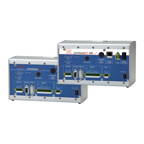
Functional Principle, Technical Data Functional Principle, Technical Data Short Description The confocalDT 2451/2461/2471LED The confocalDT 2471 measuring system includes measuring system includes - one sensor, - one sensor, - one controller IFC2451, IFC2461 - one controller (IFC2471) for the external... -
Page 10: Glossary
Functional Principle, Technical Data Glossary Start of measuring range. Minimum distance between sensor surface and target Midrange End of measuring range (start of measuring range + measuring range) Maximum distance between sensor face and target Measuring range 100 % Displacement Measuring range (MR) Sensor... -
Page 11: Technical Data
Functional Principle, Technical Data Technical Data Model 2402-0,4 2402-1,5 2402/90-1,5 2402-4 2402/90-4 2402-10 2402/90-10 Measuring range 0.4 mm 1.5 mm 1.5 mm 3.5 mm 2.5 mm 6.5 mm 6.5 mm Start of measuring range approx. 1.5 mm 0.9 mm 1.9 mm 2.5 mm 2.5 mm 2.5 mm... - Page 12 Functional Principle, Technical Data Model IFS2404-2 IFS2404-2(001) Measuring range 2 mm 2 mm Start of measuring range approx. 14 mm 14 mm 40 nm 40 nm Resolution Displacement and distance < ± 1 µm < ± 1 µm Linearity Thickness <...
- Page 13 Functional Principle, Technical Data Model 2406-2,5/VAC(003) 2406/90-2,5/VAC(001) 2406-3 2406-10 Measuring range 2.5 mm 2.5 mm 3 mm 10 mm Start of measuring range approx. 17.2 mm 75 mm 27 mm 12.6 mm 24 nm 50 nm 60 nm Resolution Displacement and distance ≤±...
- Page 14 Functional Principle, Technical Data Controller IFC2451 IFC2451MP IFC2461 IFC2461MP IFC2471LED IFC2471MP LED Multi peak measurement 2 peaks up to 6 peaks 2 peaks up to 6 peaks 2 peaks up to 6 peaks Light source internal white LED adjustable 25 / 10 / 5 / 2.5 / 1 adjustable 70 / 50 / 25 / 10 / 5 / adjustable 10 / 5 / 2.5 / 1 / 0.3 / 0.2 / 0.1 kHz...
- Page 15 Functional Principle, Technical Data Controller IFC2471 IFC2471MP Multi peak measurement 2 peaks up to 6 peaks Light source external xenon light source IFX2471 adjustable 70 / 50 / 25 / 10 / 5 / 2.5 / 1 / 0.3 kHz Measuring rate variable 70 ...
-
Page 16: Delivery
Delivery Delivery Unpacking, Included in Delivery 1 Controller IFC2451/2461/2471 1 Sensor, incl. sensor cable (optical fiber) 1 RJ patch cable Cat5 1 Test certificate 1 CD incl. operating instructions and utilities Optional for IFC2471: 1 External light source IFX2471 1 Power supply cable 1 Optical fiber cable for connecting the controller, 1 m 1 Status lead (4-pin) Check the delivery for completeness and shipping damage immediately after... -
Page 17: External Light Source Ifx2471
Assembly Sensor cable (optical fiber) approx. 75 76.2 (3) 218 (8.58) (2.95) 81.2 (3.2) (can be removed) Fig. 4 Dimension drawing of controller IFC2451/2461/2471LED, dimensions in mm, not to scale External Light Source IFX2471 Like the controller, the external light source IFX2471, see Chap. 3, may be placed onto an even surface or attached to the rear panel using a DIN rail. -
Page 18: Controller Leds
Assembly Controller LEDs Power on Green Active operating voltage No errors Flashing red Processing error Status Error during synchronization If EtherCAT is active, meaning of the LED is conform with the EtherCAT guidelines. Intensity Flashing red Dark signal acquisition in progress Signal in saturation Yellow Signal too low... -
Page 19: Electrical Controller Connections
Assembly Electrical Controller Connections 4.5.1 Handling of Pluggable Screw Terminals The controller IFC24x1 has three pluggable screw terminals for supply, digital I/O and analog out, which are included as accessories. Remove approx. 7 mm of the connecting wire isolation (0.14 ... 1.5 mm²). Connect the connecting wires. -
Page 20: Analog Output
Assembly 4.5.5 Analog Output The two alternative analog outputs (voltage or current) are connected to the 5-pin screw terminal, and both are electrically isolated from the supply voltage. Voltage: Pin U out and Pin GND U, R i approx. 30 ohm, R L > 1 kOhm, C L ≤ 10 nF; Slew rate (no C L , R L ≥... -
Page 21: Synchronization (Inputs/Outputs)
Assembly 4.5.7 Synchronization (Inputs/Outputs) For the pin assignment of the 12-pin pluggable screw terminal, see Fig. 11 Pin SyncIn/TrigIn: sync or trigger input Pin GND: ground Pin Shield: cable shield; shield is connected to the cover Pin SyncOut: sync output Pin GND: sync ground All GND pins are interconnected, and they are connected to the operating voltage ground. - Page 22 Assembly Depending on these conditions, the maximum number of controllers to be synchronized resp. the permitted total cable length can be determined graphically for synchronization f = 100 Hz ... 10 kHz f = 25 kHz f = 50 kHz f = 70 kHz 10 11 12 13 14 15 16 17 18 19 20 Number of slaves...
-
Page 23: Encoder Inputs
Assembly 4.5.8 Encoder Inputs Three encoders can be connected simultaneously and powered with 5V using the 15-pin HD-sub con- nector. Each encoder provides A, B and N signals (zero pulse, reference, index). The maximum pulse frequency is 1 MHz. Values for A, B, N: TTL level Fig. -
Page 24: Sensor Cable, Optical Fiber
Assembly Sensor Cable, Optical Fiber Sensor and controller are connected through an optical fiber. - Do not shorten or lengthen the optical fibers. - Do not pull or hold the sensor on the optical fiber. - The optical fibers has a diameter of 50 µm. Do not soil the connectors, because this would lead to particle deposition in the control- ler and therefore to strong loss of light. - Page 25 Assembly Connecting the sensor cable to the controller Remove the dummy connector from the green Sensor optical fiber socket on the controller. Plug the sensor cable (green connector, E2000/APC) into the optical fiber socket, and ensure that the sensor con- nector is aligned correctly.
-
Page 26: Sensors
Assembly Sensors 4.7.1 Dimensions IFS2402 Sensors Fiber-optic ø2.1 (.08) Fiber-optic ø 2.1 (.08) bend protection and cord grip bend protection and cord grip Titanium Lens ø1.8 housing ø4 -0,2 (.07) (.16) ø4 -0.2 (.16) Mounting area 3.75 (.15) Titanium housing 2 (.08) IFS2402-0,4/1,5/4/10 IFS2402/90-1,5/4/10... -
Page 27: Dimensions Ifs2403 Sensors
Assembly 4.7.2 Dimensions IFS2403 Sensors Fiber-optic ø2.1 (.08) Bend protection and cord grip (.18) (.03) ø8 -0,08 (dia. 0.03) ø7.95 (.06) (.19) (.31) IFS2403 -0,4/1,5/4/10 IFS2403/90-1,5 (.18) (.18) (.03) (.03) ø7.95 ø7.9 (.31) (.16) (.47) (.31) (.39) (.34) IFS2403/90-4 IFS2403/90-10 MR = Measuring range SMR = Start of measuring range Dimension in mm (Inch) -
Page 28: Dimensions Ifs2404 Sensors
Assembly 4.7.3 Dimensions IFS2404 Sensors 11.0 (.43) ø10.0 (.39) ø10.0 (.39) 12.0 (.47) ø11.0 (.43) ø12.0 (.43) IFS2404-2 IFS2404-2(001) IFS2404-2 Dimension in mm (Inch) confocalDT 24x1 Page 28... -
Page 29: Dimensions Ifs2405 Sensors
Assembly 4.7.4 Dimensions IFS2405 Sensors ø19.2 (.76) ø19.2 ø19.2 (.76) (.76) ø19.2 (.76) ø40 (1.57) ø10.4 ø14.4 (.41) ø27 ø30 (.57) ø27 - 0.05 (1.18) - 0.05 IFS2405-0,3 IFS2405-1 IFS2405-6 ø19.2 (.76) Dimension in mm (Inch) ø19.2 (.76) ø62 - 0.05 (2.44) ø19.2 (.76) -
Page 30: Dimensions Ifs2406 Sensors
Assembly 4.7.5 Dimensions IFS2406 Sensors ø16 (.63) ø16 (.63) ø ø20 (.79) (.79) appr. 12.6 (.50) 2.5 (.10) changeable ø20 glass changeable glass ø12.8 (.50) 2.0 thick IFS2406-2,5/VAC(003) IFS2406/90-2,5/VAC(001) ø 27 (1.06) ø 19.2 (.76) ø 27 (1.06) ø 19.2 (.76) ø... -
Page 31: Dimensions Ifs2407 Sensors
Assembly 4.7.6 Dimensions IFS2407 Sensors ø4.2 (.17) ø10.0 (.39) ø12.0 (.47) IFS2407-0,1 16.5 (.65) IFS2407/90-0,3 M14x0.5 Mounting SMR 5.3 ø18 (.71) Dimension in mm (Inch) (.21) confocalDT 24x1 Page 31... -
Page 32: Start Of Measuring Range
Assembly 4.7.7 Start of Measuring Range A base distance (SMR) must be maintained for each sensor. Sensor Target Fig. 17 Start of measuring range (SMR), the smallest distance between the sensor surface and the target. SMR = Start of measuring range, approximate values Sensor Sensor IFS2402-0.4... -
Page 33: Mounting An Installation Bracket
Assembly 4.7.8 Mounting an Installation Bracket 4.7.8.1 General The sensors of series IFS240x are optical sensors that operate in micrometers. Please ensure careful handling during installation and operation! Mount the sensors with a outer clamp. This type of sensor installation ensures the high- est level of reliability because the sensor’s cylindrical cover is clamped over a relatively large area. -
Page 34: Ifs2405 And Ifs2406 Sensors
Assembly 4.7.8.4 IFS2405 and IFS2406 Sensors Use an installation bracket MA240x to mount IFS2405 and IFS2406 sensors. 20 (.79) 30 (1.18) 13 (.51) (.39) (.39) Installation ring Length A Length B Length C Sensor IFS2405-0.3 IFS2405-1 MA2400-27 ø27 ø46 19.75 IFS2406-3 IFS2406-10 MA2405-34... -
Page 35: Ifs2404 And Ifs2407 Sensors
Assembly 4.7.8.5 IFS2404 and IFS2407 Sensors Use an installation bracket MA2404-12 to mount IFS2404-2 and IFS2407-0,1 sen- sors. 16 (.63) (.35) 34 (1.34) 28 (1.10) Fig. 23 Outer clamps with installation bracket MA2404-12 for IFS2404-2 and IFS2407-0,1 sensors, dimension in mm (Inch) Use the mounting area and two screws M2 or the mounting thread M14x0,5 to mount IFS2407/90 sensors. -
Page 36: Operation
Operation Operation Commissioning Connect the controller to a voltage supply, see Chap. 4.5.2. Connect the sensor and the controller with the optical fiber (sensor cable), see Chap. 4.6. If you use controller IFC2471 with an IFX2471 external light source, the following applies: Connect the controller and the external light source with the optical fiber and the status cable. -
Page 37: Access Via Ethernet
Operation Direct connection to PC, controller with static IP (Factory setting) Network PC with static IP PC with DHCP Controller with dynamic IP , PC with DHCP Connect the controller to a switch (intranet). Use a LAN cable Connect the controller to a switch with RJ-45 connectors. -
Page 38: Measured Value Presentation With Ethernet
Operation 5.2.3 Measured Value Presentation with Ethernet Start Measurement display in the horizontal navigation bar. Diagram control and display are done in the browser with HTML5 which will continue to run independently from the controller (which will also continue to operate separately). By letting the diagram display run in a separate tab or browser window, you avoid having to restart the display every time. -
Page 39: User Interface, Basic Preferences
Operation User Interface, Basic Preferences 5.3.1 Introduction The following chapters describe any controller settings that are required to get started and quickly achieve first measuring results. You can access additional submenus, e.g. for measuring rates and triggers, through the navigation bar on the left side of a web page. When programming has been completed, all settings must be permanently stored in a set of parameters to ensure that these settings will be available when the sen- sor is switched on the next time. -
Page 40: Material Database
1.585470 1.579864 Trigger mode a plastic Synchronization Micro-Epsilon assumes no responsibility for the stored material parameters. 5.3.4 Selecting a Sensor Controller and sensor(s) are matched at the factory. Select the connected sensor (type, range and serial number) from the list. -
Page 41: Exposure Mode / Measuring Rate
Operation 5.3.5 Exposure Mode / Measuring Rate To select the exposure mode click Settings > Exposure mode/Measuring rate. confocalDT 2451 Home Preferences Video signal Help/Info Measurement Save Setup Login Preferences > Exposure modes / measuring rate Exposure mode / measuring rate Measurement program Sensor Exposure mode/measuring rate... - Page 42 Operation Alternating two time mode. Operating mode with two manually preset exposure times that are used alternately. Suitable for two very different high peaks when measu- ring thickness. We recommend using this mode in particular, if the smaller peak disap- pears or the higher peak overshoots.
-
Page 43: Video Signal
Operation Video Signal After launching Video signal the following page is displayed. The diagram displayed in the large graph window on the right represents the video signal and the receiving row in different states of post processing. The video signal displayed in the graph window displays the spectral distribution of the pixels in the receiving row. - Page 44 Operation In the window on the left you can quickly adjust exposure mode, measuring rate and recognition threshold (in %). Click Submit to accept the new values. Auto (= automatic scaling) or Manual (= manual setting) allow for scaling the intensity axis (Y axis) of the graph.
-
Page 45: Dark Reference
Operation Dark Reference This adjustment must be carried out after every sensor change. Dark referencing is sensor-dependent and is stored separately in the controller for each sensor. Therefore, you need to connect the required sensor and select Settings menu > Sensor, before you start dark referencing. -
Page 46: Measurements And Web
Operation time in the case of time-critical measurements. Then gently clean the face of the sensor cable’s E2000 connector. Only use pure alcohol and fresh lens cleaning tissue to do this. Then repeat the darkness correction. If nothing changes, the sensor cable can also have become damaged or the fibre connector lying in the controller may become soiled. - Page 47 Operation Fig. 32 Measurement web page (distance measurement) By clicking on the button Resets statistics, the statistical values can be reloaded during the measurement. In stop mode, the statistical values calculated at this moment are displayed. The diagram is ended by clicking Stop; data selection and zooming is still pos- sible.
-
Page 48: Thickness Measurement Of Transparent Objects
Operation The peak intensity is displayed in form of bar graph. 10 X axis scaling: The total signal is zoomable with the slider on the left side during running measurement. The time range can be defined in the input field below the time axis. - Page 49 Operation Name State Description Intensity of at least one of the first two peaks in saturation LED 1 Intensity too low, one or both peaks below recognition Yellow Intensity threshold Green Signal ok Focus of none (or only one) of the peaks within the lin- earized or masked range LED 2 Average value from first and second peak in the midrange...
-
Page 50: Load / Save Settings In The Controller
Operation Fig. 36 Measurement web page (thickness measurement) The Measurement web page visually and numerically displays both distances and the thickness (difference 1/2), intensity is displayed for both peaks (peak 1 = close, peak 2 = far), see Fig. 36. Statistic values relate to thickness. All other settings and features are identical with those for distance measurements, see Chap. -
Page 51: Saving Settings In The Controller
Operation 5.7.1 Saving Settings in the Controller Current settings are stored in the controller using the selected parameter set number. We recommend saving settings after programming the controller, as the settings will be lost when the controller is switched off. How to save settings: Select the required setup no. -
Page 52: Advanced Settings
User level at User / Defines the user level that is enabled when the sensor starts the next time. MICRO-EPSILON recommend to restart Professional select Professional level. When an professional restores the factory settings (Settings menu > Tools > Fac- tory Settings), the Professional level password is reset to “000”. -
Page 53: Averaging, Error Handling, Spike Correction, Statistics
Advanced Settings Averaging, Error Handling, Spike Correction, Statistics 6.3.1 Notes on Averaging Video no averaging / Video averaging is carried out before measuring distances or averaging recursive 2 / 4 / 8 thickness. Recommended for very moving 2 / 4 / 3 small peaks. -
Page 54: Video Averaging
Advanced Settings Processing sequence: 1. Video averaging 2. Unlinearized distances 3. Linearizing the distances 4. Refractive index correction of the distances 5. Troubleshooting when there is no valid measured value 6. Spike correction of the distances 7. Difference generation for thicknesses 8. - Page 55 Advanced Settings Moving average in the controller IFC24x1 allows only potentials of 2 for N. The high- est averaging value is 1024. Application tips - Smooths measured values - The effect can be finely controlled in comparison with the recursive averaging - With uniform noise of the measured val- ues without spikes - At a slightly rough surface, in which the...
-
Page 56: Error Handling (Hold Last Value)
Advanced Settings 3, 5, 7 or 9 readings are taken into account. This means that individual interference pulses can be suppressed. However, smoothing of the measurement curves is not very strong. Example: Median value from five readings ... 0 1 2 4 5 1 3 Sorted measurement values: 1 2 3 4 5 Median = 3 ... -
Page 57: Statistics
Advanced Settings This function acts the same way on all output distances; the differences (thicknesses) are calculated on the basis of the corrected distances. Evaluation length. Number of previous measured values to be assessed (max. 10). Max. tolerance range (mm); the spike (outlier) correction comes into play when the value is not met or is exceeded Number of corrected value (max. -
Page 58: Zeroing, Mastering
Advanced Settings Zeroing, Mastering Use zeroing and setting masters to define a target value within the measuring range. This shifts the output range. This feature can be useful, for example, when several sensors carry out measurements simultaneously in thickness and planeness measurements. When measuring the thickness of a transparent target using controller IFC24x1, you need to specify the actual thickness of a master object as Master value. -
Page 59: Digital Interfaces
Advanced Settings Digital Interfaces Digital Output in the web diagram / Defines which interface is used for data output. No parallel data output via multiple interface Ethernet measurement transfer / channels. selection RS422 / EtherCAT Data Distance 1, 2 / Distance 3 ... 6 / Select the relevant check boxes to choose Difference 1 - 2 / Difference 1 - 3... -
Page 60: Ethernet
Advanced Settings 6.5.3 Ethernet When using a static IP address, you need to specify values for IP address, gateway and subnet mask. This is not necessary when using DHCP . The controller is preset to acquire the IP address through DHCP , and it supports link/lo- cal operation. -
Page 61: Switching Outputs
Advanced Settings Switching Outputs Assignment of the Switching output “Error 1” Error intensity (F1) / switch outputs Switching output “Error 2” Outside of measuring range (F2) / (digital I/O) F1 or F2 / Lower limit value (Gr1) / Upper limit value (Gr2) / Gr1 or Gr2 / No output Limit value settings Lower limit value (in mm) -
Page 62: Analog Output
Advanced Settings Analog Output Analog outputs can either be used for distance or thickness measurements. Only one type of measurement can be transmitted at any given time. The analog output has a resolution of 16 bit. Output signal Distance 1, 2 / Dis- With the distance measurement program tance 3 ... -
Page 63: Encoder Inputs
Advanced Settings Encoder Inputs A maximum of three encoder values can be assigned to the measured data. They will then be issued and used as trigger conditions. This exact assignment to the measured values is ensured by the fact that exactly the encoder values are output that are exist in half of the exposure time of the measured value (the exposure time may vary due to the control). -
Page 64: Maximum Value
6.10 Trigger Mode Value input and output on the confocalDT 2451/2461/2471 can be controlled through external electrical trigger signals or commands. Both analog and digital outputs are af- fected. The measured value to the trigger point is output delayed, see Chap. 6.19. -
Page 65: Triggering The Measured Value Recording
Advanced Settings Software triggering. Starts outputting values as soon as a software command (instead of the trigger input) or the Initiate trigger button is activated. The point in time is not defined as accurately. If trigger conditions are met, the controller outputs a defined number of measurements. -
Page 66: Synchronization
Advanced Settings The start of the cycle does not mean the start of the exposure time. There is only a fixed difference of 100 ns between the start of the cycle and the end of the exposure time. 6.11 Synchronization If several sensors measure the same target synchronously, the controllers may be synchronized with each other. -
Page 67: Extras
Advanced Settings 6.13 Extras Language/Sprache Deutsch / Language of the interactive web pages. English Factory Only reset Check box Enables the user to replace the currently settings current setup used setup only. Maintain interface Check box Allows to retain all Ethernet and RS422 settings interface settings without any changes. -
Page 68: Light Source Reference
Advanced Settings 6.15 Light Source Reference A light source reference is performed at the manufacturer's premises (prior to delivery). It also needs to be carried out after changing a Xenon light source (controller IFC2471), see Chap. or the LED light source (controller IFC2451, IFC2461 and IFC2471LED). Step by step: Connect the controller with the Xenon light source (using controller IFC2471). -
Page 69: Edit Material Data Bank
Advanced Settings 6.17 Edit Material Data Bank 6.17.1 Create Known Material Use the Add material button to add values to or delete values from the controller material database. Adding new material requires either the refractive index and the Abbe number vd or three refractive index numbers for wavelengths (even if they more or less coincide). - Page 70 Advanced Settings Move the measuring object with the rear edge to start of measuring range and note the current thickness value at end of measuring range. Calculate the respective refractive indices using the following formula, the nominal thickness and the three measured thicknesses. Refractive index, new material at SMR, MMR and EMR new, MBx Refractive index, raw material at SMR, MMR and EMR...
-
Page 71: Different Peak Selection In The Thickness Measurement Program
Advanced Settings 6.18 Different Peak Selection in the Thickness Measurement Program This function is used, if a material generates peaks in front of or between the ap- plied peaks caused by thin layers on the measurement object. This function should be used with care and exclusively by product specialists. -
Page 72: Timing, Measurement Value Flux
Advanced Settings 6.19 Timing, Measurement Value Flux The controller operates in cycles for measuring and processing: 1. Exposure: Charging the incoming light in the spectrometer/receiver, 2. Conversion of the video signal as digital values, 3. Computing the distance and thickness, average and so on, 4. -
Page 73: Errors, Repairs
Errors, Repairs Errors, Repairs Troubleshooting 7.1.1 Web Interface Communication If an error page is displayed in the web browser, please check the following: - Check if the controller is connected correctly, see Chap. 5.1. - Check the IP configuration for PC and controller, and check if Sensorfinder.exe (ap- plication on the CD-ROM) can locate the controller, see Chap. -
Page 74: Changing The Protective Glass For Ifs2405 And Ifs2406 Sensors
Errors, Repairs Guide the locking pin of the sensor cable into the connector cavity. Screw together the sensor's connector and socket ends. Screw the protective sleeve back onto the sen- sor. Run the dark reference, see Chap. 5.5. Changing the Protective Glass for IFS2405 and IFS2406 Sensors Changing the protective glass is required for - irreversible pollution. -
Page 75: Software Update
Obtain the firmware at the appropriate sales representatives in our house. Software Support with MEDAQLib The Micro-Epsilon Data Acquisition Library offers you a high level interface library to ac- cess confocal displacement sensors from your Windows application in combination with... -
Page 76: Software Support With Ifd2451/2461/2471 Tool
LAN cable 24 V power supply - RS422/USB converter, inclusive CD with driver You will find the actual drivers respectively program routines under: www.micro-epsilon.com/download/software/confocalDT_2451_Tool_Setup.zip www.micro-epsilon.com/download/software/confocalDT_2461_Tool_Setup.zip www.micro-epsilon.com/download/software/confocalDT_2471_Tool_Setup.zip You will find details to the driver installation in the mounting instructions „Converter RS422 to USB“. -
Page 77: Liability For Material Defects
MICRO-EPSILON with shipping costs prepaid. Any damage that is caused by improper handling, the use of force or by repairs or modifications by third parties is not covered by the liability for material defects. -
Page 78: Appendix
Appendix |Accessories, Services Appendix Accessories, Services Accessories IFS2402, IFS2403 CE2402-x Sensor cable extension for IFS2402 sensors, length x = 3 m, 10 m, 30 m, 50 m CE2402-x/PT Sensor with protective tubing, length x = 3 or 10 m, costumer-specific up to 50 m MA2402-4 Installation bracket for IFS2402-x sensors MA2403-8... - Page 79 Appendix |Accessories, Services Other accessories SC2471-x/IF2008 Interface cable for interface IF2008, length 3 m, 10 m or 20 m SC2471-x/RS422/OE Interface cable for interface IF2030, length 3 m, 10 m SC2471-3/IF2008ETH Interface cable for interface IF2008/ETH, length 3 m IF2008 Interface card IF2008 to capture four digital sensor signals synchronously, confocalDT 2421/2422/2451/2461/2471 series and two encoders.
-
Page 80: Factory Settings
Appendix |Factory Settings Factory Settings Measuring program: Distance measure- User group: Professional; password: 000 ments Measurement averaging: none Video averaging: none Statistics: all measured values Troubleshooting: Error output Select digital out: Displayed as web dia- Data selection: Distance 1 gram RS422: 115.200K Baud Ethernet: Static IP Trigger mode: no trigger... -
Page 81: A 3.3 Unpacking, Items Included In Delivery, Accessories And Installation
Appendix |Xenon Light Source IFX2471 It is not possible to manually restrict the light intensity, but controller IFC2471 can control the light exposure time. The average life span of a Xenon lamp is approximately 2000 hours, but may be less depending on frequency of operation and ambient tempera- ture. -
Page 82: A 3.4 Tips For Operation
Appendix |Xenon Light Source IFX2471 Delivery includes a spring-loaded mechanical protection cover within the fiber connector and a dummy connector. It is recommended that you remove the dummy connector to connect a fiber only when the device is switched off. Avoid any direct eye contact with the other fiber end. -
Page 83: A 3.6 Operating Elements
Appendix |Xenon Light Source IFX2471 A 3.6 Operating Elements Light exit socket. The socket is designed for E2000 fiber connectors. The dummy connector is used to prevent any direct eye contact with the light beam. Before switching on the light source, plug in the 50 µm fiber cable. Avoid any direct eye contact with the other fiber end. -
Page 84: Changing The Xenon Lamp Module
Appendix |Xenon Light Source IFX2471 A 3.7 Changing the Xenon Lamp Module Caution: While the light source is in operation, the module can reach a temperature of CAUTION approx. 250°C. Risk of burns. Please let the module cool down for at least 20 minutes, before replacing it. -
Page 85: Change Fuses
Appendix |Xenon Light Source IFX2471 Resetting the operating hours counter Plug in the power plug and the fiber cable, and turn the light source back on. Fig. 74 Operating time counter on the front of the Xenon light source Use a tool (such as a pen) to keep the switch (5) on the front of the light source pressed, see Fig. -
Page 86: A 4 Multilayer Measurement, Controller Ifc24X1Mp
Appendix |Multilayer Measurement, Controller IFC24x1MP Multilayer Measurement, Controller IFC24x1MP A 4.1 User Interface A 4.1.1 General, Settings / Measuring Program When measuring through transparent layers, each boundary area between two materials with a visually different density will reflect a part of the light. As refraction of the rays varies, all materials (refractive index) must be known. -
Page 87: A 4.1.2 Video Signal For Multilayer Measurements
Appendix |Multilayer Measurement, Controller IFC24x1MP Deactivating refractive correction A variety of factors can cause the measurement device to recognize less peaks than expected (in this example 2 peaks instead of 3, see Fig. 75): The last peak is located behind the linearized measuring range, the masked range of the CCD line or not in the CCD line at all. -
Page 88: Measurements (Measurement Values Versus Time Diagram)
Appendix |Multilayer Measurement, Controller IFC24x1MP Fig. 77 Separate peaks: Fig. 78 Peaks into each other: Measurement possible Measurement inaccuracy probably If a layer is too thin, two peaks lie near together or into each other. Please note that two approaching peaks, see Fig. - Page 89 Appendix |Multilayer Measurement, Controller IFC24x1MP Data selection 1 confocalDT 24x1 Page 89...
-
Page 90: A 4.2 Led Meaning For Multilayer Measurements
Appendix |Multilayer Measurement, Controller IFC24x1MP A 4.2 LED Meaning for Multilayer Measurements Name State Description LED 1 Intensity too high, at least one of the peaks is in satura- Intensity tion. Yellow Intensity too low, at least one of the peaks is below the recognition threshold. -
Page 91: A 4.3.1 Switching Outputs / Limit Values
Appendix |Multilayer Measurement, Controller IFC24x1MP A 4.3.1 Switching Outputs / Limit Values Use the multilayer measuring mode to freely select the measurement value to which the limit outputs relate. In addition, the selected measurement value is output via Ethernet interface. A 4.3.2 Analog Output Use the multilayer measuring mode to freely select the measurement value to be output... -
Page 92: A 5 Ascii Communication With Controller
Appendix |ASCII Communication with Controller ASCII Communication with Controller A 5.1 General The ASCII commands can be sent to the controller via the RS422 interface or Ethernet (Port 23). All commands, inputs and error messages are in English. A command always consists of the command name and zero or more parameters, which are separated by spaces and are completed with LF. - Page 93 Appendix |ASCII Communication with Controller Sensor Chap. A 5.3.3.1 SENSORTABLE Display available sensors Chap. A 5.3.3.2 SENSORHEAD Select a sensor Chap. A 5.3.3.3 SENSORINFO Sensor information Chap. A 5.3.3.4 DARKCORR Start dark reference Chap. A 5.3.3.5 DARKCORRTHRES Warning threshold in the event of contamination Chap.
- Page 94 Appendix |ASCII Communication with Controller Number of peaks, refractive correction, and material settings / multilayer measurement Chap. A 5.4.4.1 REFRACCORR Number of peaks and enabling/ disabling refractive correction Chap. A 5.4.4.2 MATERIALMP Material settings and properties MATERIALINFO Measurement value processing Chap.
-
Page 95: A 5.3 General Commands
Appendix |ASCII Communication with Controller A 5.3 General Commands A 5.3.1 General A 5.3.1.1 Help HELP [<command>] Help is displayed for a command. If no command is specified, general help information is displayed. A 5.3.1.2 Controller Information Sensor data are queried. Output as per example below: ->GETINFO Name: IFC2451... -
Page 96: A 5.3.1.5 Synchronization
Appendix |ASCII Communication with Controller A 5.3.1.5 Synchronization SYNC NONE|MASTER|SLAVE|SLAVE_EXT Setting the type of synchronization: - NONE: No synchronization - MASTER: The controller is master, ie. it transmits synchronization pulses. - SLAVE: The controller is slave and receives synchronous pulses from another IFC24x1. -
Page 97: A 5.3.2.5 Changing The Password
Appendix |ASCII Communication with Controller A 5.3.2.5 Changing the Password PASSWD <Old Password> <New Password> <New Password> Changes the password for the PROFESSIONAL level. The default (preset) password is “000”. The old password must be entered once, and the new password twice. If the new pass- words do not match, an error message is displayed. -
Page 98: A 5.3.3.6 Light Correction
Appendix |ASCII Communication with Controller A 5.3.3.6 Light Correction LIGHTCORR Performs a light correction. The correction is light source-dependent not sensor-depen- dent. The light correction is already performed by the manufacturer. For the IFC with xenon light source can this correction be performed by the user after a light source change in the user level PROFESSIONAL. -
Page 99: A 5.3.4.5 Software Trigger Pulse
Appendix |ASCII Communication with Controller A 5.3.4.5 Software Trigger Pulse TRIGGERSW Creates a software trigger pulse Error Description The controller is not in the software trigger mode, see Chap. 5.3.4.1. A 5.3.4.6 Settings Encoder Triggering TRIGGERENC 1|2|3[<Step> [<Min> [<Max>]]] Settings for the encoder triggering - 1|2|3: Selection of encoder track for the encoder triggering - Step: Number of encoder steps, after which each one a measured value is output (min: 0 max: 2... -
Page 100: A 5.3.5.5 Reset The Detection Of The First Marker Position
Appendix |ASCII Communication with Controller A 5.3.5.5 Reset the Detection of the First Marker Position ENCRESET 1|2|3 Reset the detection of the first reference marker position, see Chap. A 5.3.5.2 (only pos- sible with ENCREF ONE, otherwise the command returns immediately without an error message). -
Page 101: A 5.3.7 Parameter Management, Load / Save Settings
Appendix |ASCII Communication with Controller A 5.3.7 Parameter Management, Load / Save Settings A 5.3.7.1 Save Parameter STORE 1|2|3|4|5|6|7|8 Save the current parameter under the specified number in the flash. A 5.3.7.2 Load Parameter READ ALL|DEVICE|MEAS 1|2|3|4|5|6|7|8 Load the parameter under the specified number from the flash. In addition, the size of the loaded data needs to be specified. -
Page 102: A 5.4.1.3 Exposure Mode
Appendix |ASCII Communication with Controller A 5.4.1.3 Exposure Mode SHUTTERMODE SEARCH|MEAS|MANUAL|2TIMEALT|2TIMES SEARCH: Search mode to determine the best exposure time and measurement rate. MEAS: Exposure time is controlled automatically, measuring rate is fixed. Recommended for measurements. - MANUAL: User can select exposure time and measuring rate. - 2TIMEALT: Mode with 2 manually defined exposure times that are used alternately for two distinctly differently high peaks (for thickness measurements). -
Page 103: A 5.4.2.3 Peak Detection Threshold
Appendix |ASCII Communication with Controller A 5.4.2.3 Peak Detection Threshold THRESHOLD <Threshold> Setting the detection threshold in % (0.0 % up to 99.0 %). The detection threshold is given with two decimal places. A 5.4.3 Material Data Base A 5.4.3.1 Material Table ->MATERIALTABLE Refraction index Abbenumber... -
Page 104: A 5.4.3.5 Delete A Material
Appendix |ASCII Communication with Controller A 5.4.3.5 Delete a Material MATERIALDELETE <Name> Delete a material - Name: Name of material (Length: max. 30 characters) A 5.4.4 Number of Peaks, Material Settings Multilayer Measurements A 5.4.4.1 Number of Peaks and Enabling/Disabling Refractive Correction REFRACCORR on|off [<Number of peaks>] On: The refractive index correction is performed with the adjusted materials, default set- ting. -
Page 105: A 5.4.5.5 Reset The Statistics Calculation
Appendix |ASCII Communication with Controller A 5.4.5.5 Reset the Statistics Calculation RESETSTATISTIC Reset the statistics (of the current min and max value). A 5.4.5.6 Selection of the Signal for the Mastering / Zero Setting, Multilayer Measurement MASTERSIGNAL DIST1|DIST2|DIST3|DIST4|DIST5|DIST6|THICK12| THICK13|THICK14|THICK15|THICK16|THICK23|THICK24|THICK25| THICK26|THICK34|THICK35|THICK36|THICK45|THICK46|THICK56 Information of the signal for which the mastering or the zero setting should be applied. -
Page 106: A 5.5.2 Select Measurement Values To Be Output
Appendix |ASCII Communication with Controller A 5.5.2 Select Measurement Values to be Output Setting the values to be output via the RS422 and Ethernet interface. Maximum 32 measurement values are transmitted with RS422 in parallel. The maximum output rate via the Ethernet interface depends on the number of output values. -
Page 107: A 5.5.2.3 Data Selection Statistic Values For Rs422 And Ethernet
Appendix |ASCII Communication with Controller This setting is only available in measurement program “Thickness measurement“ resp. “Multilayer measurement”. In video mode the difference between displacement 1 and 2 can be output in addition to the video signal. Displacement 1 and 2 is output automatically when transmitting the differential value via Ethernet. -
Page 108: A 5.5.2.6 Set Video Output
Appendix |ASCII Communication with Controller A 5.5.2.6 Set Video Output OUTVIDEO NONE|[RAW] [DARK] [LIGHT] [DARKTAB] [LIGHTTAB] [THRES] Setting the data to be transmitted in a video transmission. - NONE: No video signals - RAW: Output of the unconditioned signal - DARK: Output of the dark-corrected signal - LIGHT: Output of the light source corrected signal - DARKTAB: Output of the dark-correction table - LIGHTTAB: Output of the light-correction table... -
Page 109: A 5.5.3.3 Switching Level
Appendix |ASCII Communication with Controller A 5.5.3.3 Switching Level ERRORLEVEL HIGH|LOW - HIGH: Switching output is High upon error - LOW: Switching output is Low upon error A 5.5.4 Analog Output A 5.5.4.1 Data Selection Controller IFC24x1 Controller IFC24x1MP ANALOGOUT DIST1|DIST2|THICK12 ANALOGOUT DIST1|DIST2|DIST3| DIST4|DIST5|DIST6|THICK12| THICK13|THICK14|THICK15|... -
Page 110: A 5.6 Measured Value Format
Appendix |ASCII Communication with Controller A 5.6 Measured Value Format This Chapter describes the assembly of measured value frames. Informations to transfer via Ethernet or RS422 suc- ceed, see Chap. 5.7. The data block has a fixed structure (sequence): - Video signals (+ adjustments) (N * 512 pixel * 16 bit) - Exposure time (1 * 32 bit) - Measuring rate (1 * 32 Bit) - Encoder (Ne * 32 bit) (Ne = {0, 1, 2, 3}) -
Page 111: A 5.6.2 Exposure Time
Appendix |ASCII Communication with Controller Data structure of video signals: Pixel 0 Pixel 2 ... Pixel 511 Raw signal, 16 bit Raw signal Raw signal Dark corrected signal, 16 bit Dark corrected signal Dark corrected signal Light source corrected signal, 16 bit Light source corrected Light source corrected Dark values table, 16 bit... -
Page 112: A 5.6.6 Time Stamp
Appendix |ASCII Communication with Controller are transmitted. A 5.6.6 Time Stamp Intrasystem the resolution of time stamp is 1 μs. For the Ethernet transfer a 32 bit data word (unsigned integer) with the intrasystem resolution is output. During transmission via RS422 only the bits 25 up to 8 of the time stamp are provided in a 18 bit data word. -
Page 113: A 5.6.9 Error Status
Appendix |ASCII Communication with Controller Value range 0… 33333 (IFC2471) or 0….100000 (IFC2541) A 5.6.9 Error Status Bit position Description Peak starts too early. Peak ends too late. There is no peak present. There are fewer peaks available as selected. Not all peaks are calculated, peaks are too close to each other (from 3 peaks) Peak is located in front of the measuring range (MR). -
Page 114: A 5.6.10 Differences (Thicknesses)
Appendix |ASCII Communication with Controller A 5.6.10 Differences (Thicknesses) Calculated differences between two displacements have the same format as the dis- placements. At first, the selected differences between the displacement 1 and the other displace- ments are output, then these of displacement 2,... The differences are displayed as 32 bit signed integer value with a resolution of 1 nm. -
Page 115: A 5.7.2 Measurement Data Transmission To A Measurement Value Server Via Ethernet
Appendix |ASCII Communication with Controller All values greater than 262072 are error values and are defined as follows: Error code Description 262073 Scaling error RS422 interface underflow 262074 Scaling errors RS422 interface overflow 262075 Too much data for selected baud rate 262076 There is no peak present. -
Page 116: A 5.7.2.1 Description Flags1
Appendix |ASCII Communication with Controller Example: The data encoder 1, distance and intensity are transmitted. Header Frame 1 Frame 2 Frame n Header Encoder Intensity Distance Preamble Order Serial Flags 1 Flags 2 Number of frames Counter value value value (32 Bit) Number Number... -
Page 117: A 5.7.2.3 Error Codes Ethernet Interface
Appendix |ASCII Communication with Controller A 5.7.2.3 Error Codes Ethernet Interface Error code Description 0x7ffffffb There is no peak present 0x7ffffffa Peak is located in front of the measuring range (MR) 0x7ffffff9 Peak is located behind of the measuring range (MR) 0x7ffffff8 Measuring value cannot be calculated. -
Page 118: A 5.8 Warning And Error Messages
Appendix |ASCII Communication with Controller A 5.8 Warning and Error Messages The following table lists all warning messages: Warning message Description W01 EtherCAT stopped. W02 Encoder-Triggerung stops. W03 Disable zeroing/mastering after change of sensor. W04 The output starts after switch to mode EtherCAT. - Page 119 Appendix |ASCII Communication with Controller The versions do not match (Setup file or material E21 versions do not match. table). E22 checksum invalid Checksum invalid (Setup file or material table). E23 the set of parameters does not The set of parameters does not exist. exist.
- Page 120 Appendix |ASCII Communication with Controller E54 Output of non linearized values During the output of non linearized focuses the is enabled or was trying to enable. use of statistics, averaging and analog output is Statistic, averaging and analog output not possible. are not available.
-
Page 121: Ethercat Documentation
Appendix |EtherCAT Documentation EtherCAT Documentation EtherCAT® is, from the Ethernet viewpoint, a single, large Ethernet station that transmits and receives Ethernet telegrams. Such an EtherCAT system consists of an EtherCAT master and up to 65535 EtherCAT slaves. Master and slaves communicate via a standard Ethernet wiring. On-the-fly processing hardware is used in each slave. -
Page 122: A 6.1.3 Addressing And Fmmus
Appendix |EtherCAT Documentation A 6.1.3 Addressing and FMMUs In order to address a slave in the EtherCAT® system, various methods from the master can be used. The confocalDT 24x1 supports as full slave: - Position addressing The slave device is addressed via its physical position in the EtherCAT® segment. The services used for this are APRD, APWR, APRW. -
Page 123: A 6.1.5 Ethercat State Machine
Appendix |EtherCAT Documentation A 6.1.5 EtherCAT State Machine The EtherCAT® state machine is implemented in each EtherCAT®. Directly after switch- ing on the confocalDT 24x1, the state machine is in the “Initialization“ state. In this state, the master has access to the DLL information register of the slave hardware. The mailbox is not yet initialized, i.e. -
Page 124: A 6.1.8 Service Data Sdo Service
Appendix |EtherCAT Documentation - Statistic maximum value Ethernet/EtherCAT Statistical value (maximum) - Statistic peak-peak value Ethernet/EtherCAT Statistical value (peak to peak) In EtherCAT the PDOs are transported in objects of the Sync Manager channel. The sen- sor uses the Sync Manager channel SM3 for input data (Tx data). The PDO assignments of the Sync Manager can only be changed in the “Pre-Operational”... -
Page 125: A 6.2 Coe - Object Directory
Appendix |EtherCAT Documentation A 6.2 CoE – Object Directory The CoE object directory (CANopen over EtherCAT) contains all the configuration data of the sensor. The objects in CoE object directory can be accessed using the SDO servic- es. Each object is addressed using a 16-bit index. A 6.2.1 Communication Specific Standard Objects (CiA DS-301) Overview... - Page 126 Appendix |EtherCAT Documentation Object 1009h: Hardware version 1009 Hardware version V x.xxx Visible String ro Object 100Ah: Software version 100A Software version V x.xxx Visible String ro Object 1018h: Device identification 1018 RECORD Identity Subindices Number of entries Unsigned8 Vendor ID 0x00000607 Unsigned32 Product code...
- Page 127 Appendix |EtherCAT Documentation Objects 1A01 - 1A27: TxPDO Mapping Contents are identical to object 1A00. The objects 1A01 - 1A27 are used for oversam- pling, see Chap. 6.6. Object 1C00h: Synchronous manager type 1C00 RECORD Sync manager type Subindices Number of entries Unsigned8 Sync manager 0 0x01...
-
Page 128: A 6.2.2 Manufacturer Specific Objects
Appendix |EtherCAT Documentation A 6.2.2 Manufacturer Specific Objects Overview Index (h) Name Description 2001 User level Login, logout, change password 2005 Controller info Controller informations (further) 2010 Setup Load/save settings 2011 Correction Light and dark correction 2101 Reset Reset 2105 Factory settings Reset factory settings 2140... - Page 129 Appendix |EtherCAT Documentation Object 2005h: Controller informations (further) 2005 RECORD Controller Info Subindices Number of entries Unsigned8 Name IFC24x1 Visible String ro Serial No xxxxxxxx Visible String ro Option No Visible String ro Article No xxxxxxx Visible String ro Temperature x.xx FLOAT32 The temperature (float value) is output in degree Celsius with 0.25 °C resolution.
- Page 130 Appendix |EtherCAT Documentation Object 2140h: Video 2140 RECORD Video Subindices Number of entries Unsigned8 Video type Unsigned8 Octed String Dark table xxh xxh ... [1024] Octed String Light table xxh xxh ... [1024] The entry Video type defines which signal is available in 0x6010:01. The options are: - 1 –...
- Page 131 Appendix |EtherCAT Documentation Objekt 2156h: Multilayer measurement options 2156 RECORD Multilayer options Subinzes Number of entries Unsigned8 Number of peaks for Unsigned8 multilayer Disable refractivity cor- FALSE BOOL rection Further details can be found in the chapter multilayer measurement, see Chap. Refrac count: Number of processed distances (2 ...
- Page 132 Appendix |EtherCAT Documentation Object 2181h: Averaging, error processing and statistics Averaging/error han- 2181 RECORD dling/statistics Subindices Number of entries Unsigned8 Measured value Unsigned32 averaging type Number of values for Unsigned32 moving average Number of values for Unsigned32 median Number of values for Unsigned32 recursive average Statistic depth...
- Page 133 Appendix |EtherCAT Documentation 0 - Distance 1 1 - Distance 2 2 - Distance 3 3 - Distance 4 4 - Distance 5 5 - Distance 6 32 - Difference 1 - 2 33 - Difference 1 - 3 34 - Difference 1 - 4 35 - Difference 1 - 5 36 - Difference 1 - 6 37 - Difference 2 - 3...
- Page 134 Appendix |EtherCAT Documentation Object 21B0h: Digital interfaces, selection of transmitted data (measurement values) 21B0 RECORD Digital interfaces Subindices Number of entries Unsigned8 Output device Unsigned8 RS422 baud rate Unsigned32 Ethernet/EtherCAT TRUE BOOL Distance 1 Ethernet/ TRUE BOOL EtherCAT Distance 2 Ethernet/ FALSE BOOL EtherCAT...
- Page 135 Appendix |EtherCAT Documentation Difference 2-3 Ethernet/ FALSE BOOL EtherCAT Difference 2-4 Ethernet/ FALSE BOOL EtherCAT Difference 2-5 Ethernet/ FALSE BOOL EtherCAT Difference 2-6 Ethernet/ FALSE BOOL EtherCAT Difference 3-4 Ethernet/ FALSE BOOL EtherCAT Difference 3-5 Ethernet/ FALSE BOOL EtherCAT Difference 3-6 Ethernet/ FALSE BOOL EtherCAT...
- Page 136 Appendix |EtherCAT Documentation Object 21C0h: Ethernet 21C0 RECORD Ethernet Subindices Number of entries Unsigned8 IP address xxx.xxx.xxx.xxx Visible String rw Subnet mask xxx.xxx.xxx.xxx Visible String rw Gateway xxx.xxx.xxx.xxx Visible String rw DHCP FALSE BOOL Measured value server Unsigned8 protocol Measured value server xxx.xxx.xxx.xxx Visible String rw IP-Address...
- Page 137 Appendix |EtherCAT Documentation Object 21D0h: Analog output 21D0 RECORD Analog output Subindices Number of entries Unsigned8 Analog output Unsigned8 Analog output signal Unsigned8 Analog output type of Unsigned8 scaling Analog output FLOAT32 two-point-scaling start Analog output FLOAT32 two-point-scaling end Further details can be found in the section Analog output, see Chap. 6.7, see Chap. 5.5.4.
- Page 138 Appendix |EtherCAT Documentation Object 21E0h: Zeroing/Mastering 21E0 RECORD Zeroing/Mastering Subindices Number of entries Unsigned8 Master value x.xx FLOAT32 Zeroing/Mastering FALSE BOOL active Zeroing/Mastering FALSE BOOL Reset master value FALSE BOOL Master signal Unsigned8 Further details can be found in the section Zeroing/Mastering, see Chap. and Setting masters and zero, see Chap.
- Page 139 Appendix |EtherCAT Documentation Object 21F1h: Switching outputs 21F1 RECORD Switching outputs Subindices Number of entries Unsigned8 Switching output Unsigned8 error 1 Switching output Unsigned8 error 2 Lower limit value (mm) x.xx FLOAT32 Upper limit value (mm) x.xx FLOAT32 Signal for limit value Unsigned8 output Level of switching...
- Page 140 Appendix |EtherCAT Documentation Object 2250h: Exposure mode/Measuring rate 2250 RECORD Shutter mode/measuring rate Subindices Number of entries Unsigned8 Shutter mode Unsigned8 Measuring rate Unsigned8 Shutter time 1 x.xx FLOAT32 Shutter time 2 x.xx FLOAT32 Manual measuring rate x.xx FLOAT32 Further details can be found in the section Exposure mode / Measuring rate, see Chap. 5.3.5), Exposure mode, see Chap.
- Page 141 Appendix |EtherCAT Documentation Objekt 2410h: Triggermodes 2410 RECORD Trigger mode Subindices Number of entries Unsigned8 Trigger mode Unsigned8 Trigger edge/level Unsigned8 Number of values per Unsigned16 trigger pulse Number of input for Unsigned8 encoder trigger Step width for encoder Unsigned8 trigger Minimum value for Unsigned8...
- Page 142 Appendix |EtherCAT Documentation Object 2550h: Peak detection threshold 2550 Threshold FLOAT32 Further details can be found in the section Detection threshold, see Chap. and Peak detection threshold, see Chap. 5.4.2.3. Object 25A0h: Encoder 25A0 RECORD Encoder Subindices Number of entries Unsigned8 Encoder 1 reference Unsigned32...
- Page 143 Appendix |EtherCAT Documentation Object 2711h: Reduction of region of interest 2711 RECORD Range of interest Subindices Number of entries Unsigned8 Range of interest start Unsigned32 Range of interest end Unsigned32 Further details can be found in the section Reduction of region of interest, see Chap. 6.14, see Chap.
- Page 144 Appendix |EtherCAT Documentation Object 2802h: Material table edit 2802 RECORD Material table edit Subindices Number of entries Unsigned8 Material delete Visible String rw Reset materials BOOL New material BOOL Material delete: Specification of name to be deleted from the material table Reset Materials: Resetting the material table to factory settings New material: Creating a new material in the material table.
-
Page 145: Error Codes For Sdo Services
Appendix |EtherCAT Documentation A 6.3 Error Codes for SDO Services In case of a negative evaluation of a SDO requirement, a corresponding error code is output in “Abort SDO Transfer Protocol“. Error code Meaning hexadecimal 0503 0000 Toggle-Bit has not changed. 0504 0000 SDO protocol timeout expired 0504 0001... -
Page 146: A 6.4 Measurement Data Formats
Appendix |EtherCAT Documentation A 6.4 Measurement Data Formats A 6.4.1 Measured Values - Exposure time (1 * 32 bit) - Encoder (Ne * 32 bit) (Ne = {0, 1, 2, 3}) - Measured value counter (1 * 32 bit) - Time stamp (1 * 32 bit) - Displacement values / Intensities / Unlinearized distances (n * (i+j+1) * 32 bit) - Error field (1 * 32 bit) - Differences ((n-1) * 32 bit) - Page 147 Appendix |EtherCAT Documentation Segment from Wireshark: A video signal consists of 512 pixels each with two bytes. The low byte is transmitted first, followed by the high byte. In TwinCAT the video signal can unfortunately only be displayed as hex dump. Double clicking on the index Getvideo (0x6010.1) opens the Set Value dialog.
-
Page 148: A 6.4.2.2 Video Signal Output Via Process Data
Appendix |EtherCAT Documentation A 6.4.2.2 Video Signal Output via Process Data For adding the video signal to the process data, proceed as follows: Bring the IFC24x1 in the preoperational mode. Set the measurement program on video signal output (3) using the object 0x2154 (Measuring program). - Page 149 Appendix |EtherCAT Documentation Because the object list changes, import it completely new as follows: Read the part directory e.g. Mappable Objects (TxPDO), then All Objects. confocalDT 24x1 Page 149...
- Page 150 Appendix |EtherCAT Documentation Now you can read the PDO allocations on the Process Data side from the device. After the reading: The configuration is complete after Reload Devices. confocalDT 24x1 Page 150...
- Page 151 Appendix |EtherCAT Documentation Fig. 85 Video signal and a measured value as process data Video signal Measured value confocalDT 24x1 Page 151...
-
Page 152: A 6.5 Distributed Clock
Appendix |EtherCAT Documentation A 6.5 Distributed Clock A 6.5.1 Introduction The synchronization of IFC24x1 among each other in the EtherCAT is realized via the Distributed Clock. With it it is not necessary or possible to transmit the synchro- nous signals via the synchronous input or output of the controller. Unlike the Ethernet the synchronization does not occur via external signals but about the clocks in the controllers. -
Page 153: A 6.6 Oversampling
Appendix |EtherCAT Documentation A 6.6 Oversampling The last arised measurement value data record is transmitted to EtherCAT Master with each fieldbus cycle during operation without oversampling. Many measurement value data records are not available therefore for large fieldbus cycle times. All (or selectable) measurement value data records are collected with the configurable oversampling and are transmitted together to the master with the next fieldbus cycle. - Page 154 Appendix |EtherCAT Documentation Read the PDO info on the process data tab from the IFC24x1. You can now view the size of the provided data and the mapping of SyncManager at delivery. To set the oversampling (in example 10), 10 measurement data sets (samples) selected in the PDO mapping (0x1C13).
- Page 155 Appendix |EtherCAT Documentation Load these settings with Actions / Reload Devices (F4) in the IF- C14x1. Every process data frame now contains 80 bytes measuring data (2 measurement values per 4 bytes * 10 measuring data records). confocalDT 24x1 Page 155...
- Page 156 Appendix |EtherCAT Documentation In order to ensure that no samples will disappear, due to the high asymmetry between master cycle and slave cycle, the master cycle time is subject to be less than the time which is required for the generation of a block consisting of x samples.
-
Page 157: A 6.7 Meaning Of Status-Led In Ethercat Operation
Appendix |EtherCAT Documentation A 6.7 Meaning of STATUS-LED in EtherCAT Operation STATUS-LED Green Green off INIT status Green flashing 2.5 Hz PRE-OP status Green Single Flash, 200 ms ON / 1000 ms OFF SAFE-OP status Green on OP status Status Red (are displayed in the breaks of the green LED): Red off No error... -
Page 158: A 6.8 Ethercat Configuration With The Beckhoff Twincat© Manager
Appendix |EtherCAT Documentation A 6.8 EtherCAT Configuration with the Beckhoff TwinCAT© Manager For example the Beckhoff TwinCAT Manager can be used as EtherCAT Master on the Copy the device description file (EtherCAT®-Slave Information) confocalDT24XX. xml from the included CD in the directory \\TwinCAT\IO\EtherCAT before the measu- ring device can be configured via EtherCAT®. - Page 159 Appendix |EtherCAT Documentation If ERP PREOP appears in the Current State, the cause is reported in the message window. In the example here the incorrect initialization of the synchronization manager is the reason. This will be the case if the settings for the PDO mapping in the sensor are different from the settings in the ESI file (confocalDT24XX.xml).
- Page 160 Appendix |EtherCAT Documentation Example for a complete object directory (subject to change without prior notice). On the Process Data side the PDO allocations can be read from the device. The scope of the provided process data and the assignment of the SyncManager may be viewed now.
- Page 161 Appendix |EtherCAT Documentation Now select the tab Reload Devices under the menu item Actions. The configuration is now complete. The selected measurement values are transmitted as process data in the status SAFEOP and OP. confocalDT 24x1 Page 161...
-
Page 162: Operating Menu
Appendix |Operating Menu Operating Menu Login Announced user level Value only reading Change to user- / professional Button logoff or enter password level Old password Value Change password New password Value Repeat new password Value User level by restart Professional / User Type of measure- Distance Used peak... - Page 163 Appendix |Operating Menu Averaging, Video averaging Recursive 2 / 4 / 8 The video averaging is carried out before error handling, measuring distances or thickness. Recom- Moving 2 / 4 / 3 statistics mended for very small peaks. Median 3 / No averaging Measured value Specify the type of averaging.
- Page 164 Appendix |Operating Menu Digital interfaces Digital interface Output in the web diagram/ Ether- Defines which interface is used for data selection net measurement transfer / RS422 output. No parallel data output via multiple / EtherCAT channels. Data selection Distance 1, 2 / Distance 3 ...
- Page 165 Appendix |Operating Menu Encoder Encoder 1 / 2 / 3 Interpolation Single / Double / Quadruple resolution inputs No effect / Set on first track /Set with every Effect on reference track track Starting value is less than Set on value Value max.
- Page 166 X9751238-C031079SWE MICRO-EPSILON MESSTECHNIK GmbH & Co. KG Königbacher Str. 15 · 94496 Ortenburg / Germany MICRO-EPSILON MESSTECHNIK Tel +49 (0) 8542 / 168-0 · Fax +49 (0) 8542 / 168-90 *X9751238-C03* info@micro-epsilon.de · www.micro-epsilon.com...
Need help?
Do you have a question about the confocalDT 2451 and is the answer not in the manual?
Questions and answers