Table of Contents
Advertisement
Quick Links
Advertisement
Table of Contents

Subscribe to Our Youtube Channel
Related Manuals for MICRO-EPSILON combiSENSOR 64x0


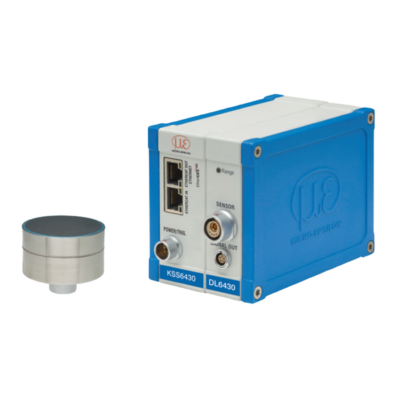
Summary of Contents for MICRO-EPSILON combiSENSOR 64x0
- Page 1 Instruction Manual combiSENSOR 64x0...
- Page 2 MICRO-EPSILON MESSTECHNIK GmbH & Co. KG Königbacher Straße 15 94496 Ortenburg / Germany Tel. +49 (0) 8542 / 168-0 Fax +49 (0) 8542 / 168-90 e-mail info@micro-epsilon.de www.micro-epsilon.com...
-
Page 3: Table Of Contents
Ground Connection, Earthing ........................22 Electrical Connections ........................... 23 4.6.1 Connectivity Options ........................23 4.6.2 Pin Assignment Supply, Trigger ....................24 4.6.3 Analog Output ..........................24 Operation ..........................26 Starting Up ..............................26 LED’s on the Controller ..........................27 combiSENSOR 64x0... - Page 4 Access Controller Information (COI) .................... 43 6.4.17 Login for Web Interface (LGI) ....................... 44 6.4.18 Logout for Web Interface (LGO) ....................44 6.4.19 Change Password (PWD)......................44 6.4.20 Change Language for the Web Interface (LNG) ................45 6.4.21 Default Messages ........................45 combiSENSOR 64x0...
- Page 5 CoE – Object Directory ..........................63 A 2.2.1 Communication Specific Standard Objects (CiA DS-301) ............63 A 2.2.2 Manufacturer Specific Objects ..................... 65 A 2.3 Measurement Data Format ..........................68 A 2.4 EtherCAT Configuration with the Beckhoff TwinCAT©-Manager ..............69 combiSENSOR 64x0...
- Page 6 64x0...
-
Page 7: Safety
The power supply may not exceed the specified limits. > Damage to or destruction of the sensor and/or controller Protect the sensor cable against damage > Destruction of the sensor > Failure of the measuring device combiSENSOR 64x0 Page 7... -
Page 8: Notes On Ce Marking
The measuring system is designed for use in industrial environments and meets the requirements. Intended Use - The combiSENSOR 64x0 measuring system is designed for use in industrial and laboratory applications. It is used for ƒ measuring film thickness of plastics ƒ... -
Page 9: Proper Environment
- The space between the sensor surface and the target must have an unvarying dielectric constant. - The space between the sensor surface and the target may not be contaminated (for example water, rubbed-off parts, dust, etc.) combiSENSOR 64x0 Page 9... -
Page 10: Functional Principle, Technical Data
The measured AC voltage is demodulated, amplified and output as an analog voltage. The sensor design with guard ring electrodes guarantees that the ideally necessary homogenous electrical field is realized for all practical purposes. A measurement object that is too small and curved (uneven) measurement surfaces also produce a non-linear characteristic. combiSENSOR 64x0 Page 10... -
Page 11: Eddy Current Principle
Through the redundancy of this combined sensor principle, the measured thickness value remains unaffected by any changes in the measurement setup. The target thickness T is calculated from both sensor signals. combiSENSOR 64x0 Page 11... - Page 12 Signal eddy sensor [%] Signal capacitive sensor [%] T = S (eddy) - A (capa) * + Offset Dielectric constant (insulator) 100 % Working distance [µm] Offset Constant [µm], standard value = 0 combiSENSOR 64x0 Page 12...
-
Page 13: Structure
In order to obtain accurate measuring results, the surface of the sensor must be kept clean and free from damage. The capacitive measuring process is area-related. The combiSENSOR requires a minimum area of ø 45 mm (KSH5) or ø 65 mm (KSH10). combiSENSOR 64x0 Page 13... -
Page 14: Sensor Cable
The capacitive and eddy current part of the sensor are synchronized with each other. Ethernet / EtherCAT Sensor Power supply, Trigger In Eddy and capa signal differential and temperature signal Fig. 4 Controller measuring system combiSENSOR 64x0 Page 14... -
Page 15: Technical Data
Reference material ground electrode: VA steel (1.4571) or aluminium. Changes of the ground electrode (material or geometry) require a recalibration of sensor and controller by the manufacturer. Circumferential clamping starts 5 mm behind the sensor surface, see Fig. combiSENSOR 64x0 Page 15... -
Page 16: Delivery
If there is damage or parts are missing, immediately contact the manufacturer or supplier. Storage - Storage temperature ƒ Sensor, sensor cable -10 °C to +100 °C (+14 to +212 °F) ƒ Controller 10 to +75 °C (+50 to +167 °F) - Humidity 5 - 95 % (no condensation) combiSENSOR 64x0 Page 16... -
Page 17: Installation And Assembly
Make sure when assembling the sensor that there are no metallic conductive objects within the gray marked area, see Fig. 6. Else the linearity may be changed of the eddy current sensor by up to about 1 % of measuring range. combiSENSOR 64x0 Page 17... - Page 18 This sensor mounting option offers maximum reliability because the sensor is clamped around its cylindrical housing. It is absolutely necessary in difficult installation environments, for example on machines, production plants et cetera. Mounting with a clamping ring Fig. 7 Circumferential clamping Pulling on the cable is inadmissible. combiSENSOR 64x0 Page 18...
-
Page 19: Sensor Cable
The connection is made by simple plugging. The connector locks automatically. The tight fit can be checked by pulling the connector housing (cable bushing). A damaged cable cannot be repaired. 1000 (39.4) ±1 % appr. 50 (2.0) Legend mm (inches) appr. 38 (1.5) Fig. 8 Dimensions sensor cable combiSENSOR 64x0 Page 19... -
Page 20: Controller
Installation and Assembly Controller 75 (2.95) 125 (4.92) Legend mm (inches) KSS6430 DL6430 Fig. 9 Dimensional drawing controller with basic unit, demodulator module and housing cover Dimensions in mm (inches), not to scale combiSENSOR 64x0 Page 20... - Page 21 Fig. 10 Dimensional drawing housing cover Dimensions in mm (inches), not to scale The controller is mounted using mounting plates or holding clamps for a mounting on DIN-rail which are included with the conversion kit supplied. combiSENSOR 64x0 Page 21...
-
Page 22: Ground Connection, Earthing
Make sure you have a sufficient grounding of the measuring object, for example connect it with the sen- sor or the supply ground. If necessary use the ground connection on the housing cover. The ground connection is included with the conversion kit supplied. combiSENSOR 64x0 Page 22... -
Page 23: Electrical Connections
4.6.1 Connectivity Options The power supply and the signal output are located at the front side of the controller. Controller LAN cable with RJ-45 connectors EtherCAT Ethernet PS 2020 Sensor DDxx Fig. 11 Measuring system assembly combiSENSOR 64x0 Page 23... -
Page 24: Pin Assignment Supply, Trigger
Differential signal 0 ... 10 V (eddy current - capacitive signal) or thickness Capacitive signal 0 ... 10 V Eddy current signal 0 ... 10 V Solder pin side male cable connector Sensor temperature signal, not scaled combiSENSOR 64x0 Page 24... - Page 25 Differential signal (= eddy current - capacitive signal) or thickness signal, 0 ... 10 V grey Capacitive signal (0 ... 10 V) yellow Eddy current signal (0 ... 10 V) green Sensor temperature signal, not scaled brown combiSENSOR 64x0 Page 25...
-
Page 26: Operation
, always the Ethernet interface is active independent of the software EN/EC setting. If the switch is in position (Ethernet/EtherCAT), then the active interface depends on the software setting. To change the interface it is necessary to restart the controller. combiSENSOR 64x0 Page 26... -
Page 27: Led's On The Controller
Range Working distance exceeded DL6430 Triggering The measuring value output on combiSENSOR 64x0 is controllable by an external electrical trigger signal or command. Here, only the digital output is affected. Triggering release by: Controller I = 5 ... 45 mA... - Page 28 Software triggering ($GMD). A measuring value is output per channel, as soon as a command is sent. The point of time is not defined as accurately. No trigger is set ex factory. The controller starts the data transfer immediately after the switching on. combiSENSOR 64x0 Page 28...
-
Page 29: Measurement Averaging
Example with N = 7: 2+3+4+5+6+7+8 ..0 1 2 3 4 5 6 7 8 gets to Average value n 3+4+5+6+7+8+9 gets to Average value n +1 ..1 2 3 4 5 6 7 8 9 combiSENSOR 64x0 Page 29... -
Page 30: Arithmetic Average Value
For that purpose the signal noise is calculated dynamically and measurement changes are only transferred, if they exceed this calculated noise. Thereby at a change in direction of the measurement signal small hystere- sis effects in the size of the calculated noise can occur. combiSENSOR 64x0 Page 30... -
Page 31: Ethernet Interface
The data logging of all channels is synchronous. Connect the combiSENSOR 64x0 to an available Ethernet interface at the PC. Use a crossover cable. For a connection with the combiSENSOR 64x0 you will require a defined IP address of the network interface Control Panel\Network Connections. - Page 32 Ethernet Interface Define the following address in the properties of the LAN connection: IP address: 169.254.168.1 Subnet mask: 255.255.0.0 Properties. Internet Protocol (TCP/IP Select Select ) > Properties. combiSENSOR 64x0 Page 32...
- Page 33 The controller supports UPnP . If you use an operational system with activated UPnP client e. g. standard with Windows 7, the controller is listed in the explorer as a device automatically. This is helpful, if you do not know the IP address of the controller. combiSENSOR 64x0 Page 33...
-
Page 34: Data Format Of Measuring Values
[number channels N] 32 bit All measuring values are transmitted as Int32. The measuring value resolution is 24 bits i.e only the most low- order 24 bits of integer number are used. Hexadecimal range: 0 ... FFFFFF combiSENSOR 64x0 Page 34... - Page 35 By default, the measuring values are continuously output with the set data rate via the data port. However, there is also a trigger mode, with can be used to get the individual measuring values, see Chap. 6.4.2. combiSENSOR 64x0 Page 35...
-
Page 36: Settings
The controller immediately returns all transmitted characters back as echo. Commands are transmitted in ASCII format. A time out is reached approximately 10 seconds after the last character input. Commands always have to end with <CR> or <CRLF>. combiSENSOR 64x0 Page 36... -
Page 37: Data Rate (Sti)
10.4 Sa/s 64000 15.6 Sa/s 38400 26 Sa/s 32000 31.3 Sa/s 19200 52.1 Sa/s 16000 62.5 Sa/s 9600 104.2 Sa/s 1920 520.8 Sa/s 1041.7 Sa/s 2083.3 Sa/s 3906.3 Sa/s Request sample time Command $STI?<CR> Response $STI?nOK<CRLF> combiSENSOR 64x0 Page 37... -
Page 38: Trigger Mode (Trg)
Irrespective of the trigger mode set, a single measured value per channel can be called up by means of a software command, see Chap. 5.4.3. If the trigger mode is turned off, the combiSENSOR 64x0 will send the measurement values without interruption and with the adjusted data rate. -
Page 39: Filter, Averaging Type (Avt)
Number of measuring values used to calculate the average (adjustable from 2 … 8) Command $AVNn<CR> Response $AVNnOK<CRLF> Index n = 2 ... 8 ? = Request averaging number Request averaging number Command $AVN?<CR> Response $AVN?nOK<CRLF> combiSENSOR 64x0 Page 39... -
Page 40: Thickness Measurement (Thm)
Specifies in increasing order in which channels there is a module. (0 = no channel available, 1 = channel available, 2 = thickness function is output on this channel) Command $CHS<CR> Response $CHS2,1,1,1OK<CRLF>(Example: Channel 1,2,3,4 available, channel 1 with thickness function) combiSENSOR 64x0 Page 40... -
Page 41: Status (Sts)
Response $IPSm,<IPAddress>,<SubnetAddress>,<GatewayAddress>OK<CRLF> Index m = 0: static IP address m = 1: activates DHCP* * If DHCP is active, no IP subnet- and gateway address has to be transmitted. Request settings Command $IPS? Response $IPS? m,<IPAddress>,<SubnetAddress>,<GatewayAddress>OK<CRLF> combiSENSOR 64x0 Page 41... -
Page 42: Change Between Ethernet And Ethercat (Ifc = Interface)
Queries the port number of the data port. Command $GDP<CR> $GDP<Port number>OK<CRLF> Response Example: $GDP10001OK<CRLF> 6.4.14 Set Data Port (SDP) Sets the port number of the data port. Range: 1024 ...65535. Command $SDP<Portnumber><CR> Example: $SDP10001OK<CR> Response $SDP<Portnumber>OK<CRLF> combiSENSOR 64x0 Page 42... -
Page 43: Access Channel Information (Chi)
6.4.16 Access Controller Information (COI) Reads information of the controller (e.g. serial number). Command $COI<CR> Response $COIANO...,NAM...,SNO...,OPT...,VER...OK<CRLF> Index ANO = Article number NAM = Name SNO = Serial number OPT = Option VER = Firmware version combiSENSOR 64x0 Page 43... -
Page 44: Login For Web Interface (Lgi)
Changes the password of the device (required for the web interface and the SensorFinder). Command $PWD<oldpassword>,<newpassword>,<newpassword><CR> $PWD<oldpassword>,<newpassword>,<newpassword>OK< CRLF> Response A password can be from 0-16 characters and must contain only letters and numbers. When delivered, no password is assigned. The field can remain empty/blank. combiSENSOR 64x0 Page 44... -
Page 45: Change Language For The Web Interface (Lng)
IP address of the controller to the list of addresses which should not be routed through the proxy server. “ Javascript” must be enabled in the browser so that measurement results can be displayed graphically. combiSENSOR 64x0 Page 45... - Page 46 Start a web browser on your PC. To achieve a dress: 169.254.168.1. controller with the serial number “01234567”, type in the address bar on your browser “KSS6430_01234567”. Interactive web pages for setting the controller and peripherals are now shown in the web browser. combiSENSOR 64x0 Page 46...
-
Page 47: Access Via Web Interface
Parallel operation with web interface and Telnet commands is possible; the last setting applies. The appearance of the web pages may vary depending on functions and peripherals. Each page contains parameter descriptions and tips on completing the controller. combiSENSOR 64x0 Page 47... - Page 48 Operating Menu, Set Controller Parameter Preliminary Notes to the Settings You can program the combiSENSOR 64x0 at the same time in two different kinds: - Using a web browser via the sensor web interface - With ASCII command set and terminal program via Ethernet (Telnet) Login, Changing User Level Assigning passwords prevents unauthorized changes to controller settings.
- Page 49 User level at restart User / Defines the user level that is enabled when the sensor starts the next Professional time. MICRO-EPSILON recommend to select User level. Old Password With the first-time assignment of a password the field remains free.
-
Page 50: Thickness Measurement
Signal capacitive sensor [%] T = S (eddy) - A (capa) * + Offset 100 % Dielectric constant (insulator) Working distance [µm] Offset Constant [µm], standard value = 0 Fig. 22 Menu Settings > Thickness measurement combiSENSOR 64x0 Page 50... - Page 51 Value range: 5000 µm or 10000 µm. Step 4: Enter the thickness value [µm] of the master Thickness object Value target. Value Calculated dielectric constant Dielectric constant Clicking onto the button starts the calculation of the Calculate dielectric constant combiSENSOR 64x0 Page 51...
-
Page 52: Trigger Mode
Chap. 4.6.2 or by the command $ GMD, see Chap. 6.4.3. If the trigger mode is turned off, the combiSENSOR 64x0 will send the measuring values without interruption and with the adjusted data rate. Rising edge A measuring value is output per edge. -
Page 53: Digital Interfaces
The controller has a firmware update function. We recommend to always use the latest firmware version. You can find the latest firmware version on our website and it can be installed with the attached Firmware Update Tool. combiSENSOR 64x0 Page 53... -
Page 54: Ethercat Interface
(Ethernet) Regardless to the software setting always the Ethernet interface is active. EN/EC Active interface, which (Ethernet/EtherCAT) is set via the web inter- face or command. Fig. 23 Switch to change the interface, basic module KSS6420 combiSENSOR 64x0 Page 54... -
Page 55: Operation And Maintenance
94496 Ortenburg / Germany identifiable, the whole measuring system must be sent back for repair or replacement to: Tel. +49 (0) 8542 / 168-0 Fax +49 (0) 8542 / 168-90 info@micro-epsilon.de www.micro-epsilon.com combiSENSOR 64x0 Page 55... -
Page 56: Liability For Material Defects
The liability for material defects is 12 months from delivery. Within this period, defective parts, except for wearing parts, will be repaired or replaced free of charge, if the device is returned to MICRO-EPSILON with shipping costs prepaid. Any damage that is caused by improper handling, the use of force or by repairs or modifications by third parties is not covered by the liability for material defects. -
Page 57: Appendix A 1 Accessories
Appendix| Accessories Appendix Accessories SCACx/5 Signal output cable analog, x m long PS2020 Power supply for mounting on DIN-rail input 230 VAC (115 VAC) output 24 VDC / 2.5 A; L/W/H 120 x 120 x 40 mm combiSENSOR 6430 Page 57... -
Page 58: Ethercat Documentation
Appendix| EtherCAT Documentation EtherCAT Documentation EtherCAT® is, from the Ethernet viewpoint, a single, large Ethernet station that transmits and receives Ether- net telegrams. Such an EtherCAT system consists of an EtherCAT master and up to 65535 EtherCAT slaves. Master and slaves communicate via a standard Ethernet wiring. On-the-fly processing hardware is used in each slave. -
Page 59: A 2.1.2 Ethercat® Services
Appendix| EtherCAT Documentation A 2.1.2 EtherCAT® Services In EtherCAT® services for the reading and writing of data are specified in the physical memory of the slave hardware. The following EtherCAT® services are supported by the slave hardware: - APRD (Autoincrement physical read, Reading of a physical area with auto-increment addressing) - APWR (Autoincrement physical write, Writing of a physical area with auto-increment addressing) - APRW (Autoincrement physical read write, Reading and writing of a physical area with auto-increment ad- dressing) -
Page 60: A 2.1.3 Addressing And Fmmus
Appendix| EtherCAT Documentation A 2.1.3 Addressing and FMMUs In order to address a slave in the EtherCAT® system, various methods from the master can be used. The KSS6430 supports as full slave: - Position addressing The slave device is addressed via its physical position in the EtherCAT® segment. The services used for this are APRD, APWR, APRW. -
Page 61: Ethercat State Machine
Appendix| EtherCAT Documentation A 2.1.5 EtherCAT State Machine The EtherCAT® state machine is implemented in each EtherCAT®. Directly after switching on the combiSEN- SOR 64x0, the state machine is in the “Initialization“ state. In this state, the master has access to the DLL information register of the slave hardware. -
Page 62: A 2.1.6 Canopen Over Ethercat
Tx PDOs are used for the transmission of data from the slaves to the master (inputs), Rx PDOs are used to transmit data from the master to the slaves (outputs); not used in the combiSENSOR 64x0. The PDO mapping defines which application objects (measurement data) are transmitted into a PDO. The combiSEN- SOR 64x0 has a Tx PDO for the measuring data. -
Page 63: A 2.2 Coe - Object Directory
Appendix| EtherCAT Documentation A 2.2 CoE – Object Directory The CoE object directory (CANopen over EtherCAT) contains all the configuration data of the sensor. The objects in CoE object directory can be accessed using the SDO services. Each object is addressed using a 16-bit index. - Page 64 Appendix| EtherCAT Documentation Object 1009h: Hardware version 1009 Hardware version V x.xxx Visible String Object 100Ah: Software version 100A Software version V x.xxx Visible String Object 1018h: Device identification 1018 RECORD Identity Subindices Number of entries Unsigned8 Vendor ID 0x0000065E Unsigned32 Product code 0x003EDE73...
-
Page 65: A 2.2.2 Manufacturer Specific Objects
Appendix| EtherCAT Documentation Object 1C13h: TxPDO assign 1C13 RECORD TxPDO assign Subindices Number of entries Unsigned8 Subindex 001 0x1A00 Unsigned16 A 2.2.2 Manufacturer Specific Objects Overview Index (h) Name Description 2010 Controller info Controller information 2020 Channel 1 Info Information and settings of channel 1 2021 Channel 2 Info Information and settings of channel 2... - Page 66 Appendix| EtherCAT Documentation Object 2010h: Controller information 2010 RECORD Controller info Subindices Number of entries Unsigned8 Name DT6230 Visible String Serial No xxxxxxxx Unsigned32 Article No xxxxxxx Unsigned32 Option No Unsigned32 Firmware version Visible String Object 2020h: Channel information 2020 RECORD Channel 1 info Subindices...
- Page 67 Appendix| EtherCAT Documentation Object 2060h: Controller settings 2060 RECORD Controller Settings Subindices Number of entries Unsigned8 Sample rate 2083.3 Hz Enum Averaging type Enum Averaging number Enum Trigger Enum Object 2100h: Controller interface 2100 RECORD Controller Interface Subindices Number of entries Unsigned8 Ethernet/EtherCAT EtherCAT...
-
Page 68: Measurement Data Format
Appendix| EtherCAT Documentation Object 2200h: Commands 2200 RECORD Commands Subindices Number of entries Unsigned8 Command AVT1 Visible String Command Response AVT1OK Visible String Any commands can be sent to the controller with the object 2200h, for example, the thickness functions as these are not defined in the COE objects. -
Page 69: A 2.4 Ethercat Configuration With The Beckhoff Twincat©-Manager
A 2.4 EtherCAT Configuration with the Beckhoff TwinCAT©-Manager For example the Beckhoff TwinCAT Manager can be used as EtherCAT Master. Micro-Epsilon.xml Copy the device description file (EtherCAT®-Slave Information) from the in- cluded CD in the directory \\TwinCAT\IO\EtherCAT (for TwinCATV2.xx) or \\TwinCAT\3.1\Config\IO\Ether- CAT (for TwinCAT V3.xx), before the measuring device can be configured via EtherCAT®. - Page 70 Appendix| EtherCAT Documentation Scan for boxes The window (EtherCAT®-Slaves) appears. Confirm with Confirm with Solution explorer The combiSENSOR 64x0 is now listed in the Activate Free Run Now confirm the window with combiSENSOR 6430 Page 70...
- Page 71 Appendix| EtherCAT Documentation PREOP, SAFEOP Online The current status should be at least on the side. Example for a complete object directory (subject to change without prior notice). Process data On the side the PDO allocations can be read from the device. combiSENSOR 6430 Page 71...
- Page 72 Appendix| EtherCAT Documentation SAFEOP The selected measuring values are transmitted as process data in the status combiSENSOR 6430 Page 72...
- Page 74 MICRO-EPSILON MESSTECHNIK GmbH & Co. KG X9751369-A041058MSC Königbacher Str. 15 · 94496 Ortenburg / Germany MICRO-EPSILON MESSTECHNIK Tel. +49 (0) 8542 / 168-0 · Fax +49 (0) 8542 / 168-90 *X9751369-A04* info@micro-epsilon.de · www.micro-epsilon.com...
Need help?
Do you have a question about the combiSENSOR 64x0 and is the answer not in the manual?
Questions and answers