Advertisement
Quick Links
1.
Warnings
Connect the power supply and the display-/output device according to the safety
regulations for electrical equipment. The supply voltage must not exceed the specified
limits.
> Risk of injury, damage to or destruction of the sensor
Avoid shocks and impacts to the sensor. Avoid constant exposure of the sensor to dust
and splashes of water. Avoid exposure of sensor to aggressive materials (detergents,
cooling emulsions).
> Damage to or destruction of the sensor
Read the detailed operation instructions before operating the sensor.
These instructions are available Online at www.micro-epsilon.com.
2.
Notes on CE Marking
The following apply to the scanCONTROL 2910/2960-xx/BL:
- EU Directive 2014/30/EU
- EU Directive 2011/65/EU
The sensor is designed for use in industrial environments.
The sensor satisfies the requirements if the guidelines in the operation instructions are
maintained in installation and operation.
3.
Proper Environment
- Protection class:
- Temperature range:
ƒ Operation:
ƒ Storage:
- Humidity:
scanCONTROL 2910/2960BL
Assembly Instructions
scanCONTROL
IP65
0 ... +45 °C (+32 ... +113 °F), for free circulation of air
-20 ... +70 °C (-4 ... +158 °F)
5 - 95 % (non-condensing)
2910/2960BL
Page 1
Advertisement

Related Manuals for MICRO-EPSILON scanCONTROL 2910


Summary of Contents for MICRO-EPSILON scanCONTROL 2910
- Page 1 Read the detailed operation instructions before operating the sensor. These instructions are available Online at www.micro-epsilon.com. Notes on CE Marking The following apply to the scanCONTROL 2910/2960-xx/BL: - EU Directive 2014/30/EU - EU Directive 2011/65/EU The sensor is designed for use in industrial environments.
-
Page 2: Laser Safety
Laser Safety The Sensoren scanCONTROL 2910/2960-xx/BL operate with a semiconductor laser with a wavelength of 405 nm (visible/blue). Operation of the laser is indicated visually by the LED on the sensor, see operating instructions, Chap. 3.3. When operating the scanCONTROL 29xx sensors, the relevant regulations according to IEC 60825, Part 1 of 05/2014 and the applicable accident prevention regulations must be followed. -
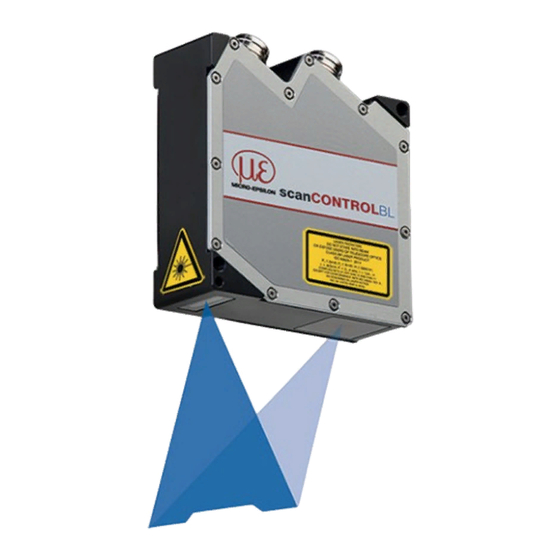
Page 3: Unpacking, Included In Delivery
Fig. 1 Sensor with laser labels Unpacking, Included in Delivery - 1 scanCONTROL 2910/2960-xx/BL sensor with integrated controller - 1 PCR3000-5 multifunction cable, length 5 m; for power supply, trigger and RS422; screw connector and free cable ends - Calibration protocol / assembly instructions... - Page 4 The RS422 connection (Pin 11 and 12 of the multifunction port) can be used in either of the following configurations: - RS422 (half-duplex): Load user modes and sensor control, sensor control and transmission of measurement results (Modbus RTU or ASCII format) - Synchronization/triggering: Synchronization or triggering using switching signals scanCONTROL 2910/2960BL Page 4...
- Page 5 Use a serial key switch in the control circuit to switch off the laser. With standard sensors, connecting the supply voltage activates the laser light source in the sensor. Wiring details are available in the operating instructions, Chap. 5.2.6. scanCONTROL 2910/2960BL Page 5...
- Page 6 > Damage to the sensor and /or Ethernet card! - A fixed IP address can be assigned. Use the sensorTOOL program to make specify the sensor settings described above. The program is available Online at https://www.micro-epsilon.de/service/download/ software. scanCONTROL 2910/2960BL Page 6...
-
Page 7: Transmitting Measurement Results
- 1 GB RAM - Screen resolution: 1024x768 - Graphic card / GPU with OpenGL 3.1 or higher Transmitting Measurement Results scanCONTROL 2910/2960BL offers the following options for transmitting measurement results: - Ethernet interface ƒ Modbus TCP protocol ƒ UDP protocol ƒ... - Page 8 Only connect the sensor to the peripheral equipment, if it is disconnected from the power supply, i.e. only when the supply voltage is switched off. The sensor needs a warm-up time of typically 20 minutes for high precision measurements. scanCONTROL 2910/2960BL Page 8...
- Page 9 Profile data of scanCONTROL can be accessed via: - GigEVision and GenICam for digital cameras via Ethernet - SDK for fast application integration (C, C++, C# and others) Please refer to the respective SDK documentation for further information on accessing the profile data. scanCONTROL 2910/2960BL Page 9...
- Page 10 2910/2960BL with scanCONTROL Output Status of supply voltage Status 13 14 13 14 - Power contacts DO 1 LINK ETHERNET ACT 1 - System LINK DO 7 Data contacts A1 A2 Ñ System supply (OUT) 0: WBM 24 V...
-
Page 11: Additional Information
Tools operating instructions. You will find details about the individual programs in the respective operating instruc- tions or in the operating instructions of this sensor, Chap. 6.2. You will find the operating instructions Online at www.micro-epsilon.com. scanCONTROL 2910/2960BL Page 11... - Page 12 Measurement values are transmitted at up to 500 Hz. Please refer to TechNote T026 (scanCONTROL fieldbus integration) for more details. www.micro-epsilon.com MICRO-EPSILON Messtechnik GmbH & Co. KG Koenigbacher Str. 15 94496 Ortenburg / Germany, Tel. +49 (0) 85 42/1 68-0 Your local contact: www.micro-epsilon.com/contact/worldwide/...
Need help?
Do you have a question about the scanCONTROL 2910 and is the answer not in the manual?
Questions and answers