Table of Contents
Advertisement
Quick Links
CLS1000-AU
CLS1000-AI
CLS1000-QN
CLS1000-2Q
CLS1000-OC
MICRO-EPSILON Eltrotec GmbH
Manfred-Wörner-Straße 101 · 73037 Göppingen / Germany
Tel. +49 (0) 7161/98872-300 · Fax +49 (0) 7161/98872-303
eltrotec@micro-epsilon.com · www.micro-epsilon.com
Your local contact:
www.micro-epsilon.com/contact/worldwide/
Operating Instructions
optoCONTROL
CLS1000
Advertisement
Table of Contents

Related Manuals for MICRO-EPSILON optoCONTROL CLS1000


Summary of Contents for MICRO-EPSILON optoCONTROL CLS1000
- Page 1 Operating Instructions optoCONTROL CLS1000 CLS1000-AU CLS1000-AI CLS1000-QN CLS1000-2Q CLS1000-OC MICRO-EPSILON Eltrotec GmbH Manfred-Wörner-Straße 101 · 73037 Göppingen / Germany Tel. +49 (0) 7161/98872-300 · Fax +49 (0) 7161/98872-303 eltrotec@micro-epsilon.com · www.micro-epsilon.com Your local contact: www.micro-epsilon.com/contact/worldwide/...
- Page 2 Sensory system for detecting presence, position, turbidity, gap, diameter and edges MICRO-EPSILON Eltrotec GmbH Manfred-Wörner-Straße 101 73037 Göppingen / Germany Tel. +49 (0) 7161 / 98872-300 Fax +49 (0) 7161 / 98872-303 e-mail eltrotec@micro-epsilon.com www.micro-epsilon.com...
-
Page 3: Table Of Contents
2PT / 2Point Teach-in ....................36 5.4.3.9 MST / ManualSensitive Teach-in ................36 5.4.4 Q1 / Config Q1 ..........................37 5.4.4.1 OPM / Switching Polarity ..................37 5.4.4.2 TIME / Timer ......................37 5.4.4.3 Q2 / Config Q2 ......................37 optoCONTROL CLS1000... - Page 4 Optional Accessories ......................47 Factory Settings ........................48 Circuit Examples ........................49 A 3.1 CLS1000-QN and CLS1000-2Q ........................49 A 3.2 CLS1000-OK ..............................50 A 3.3 CLS1000-AU ..............................50 A 3.4 CLS1000-AI ..............................51 A 3.5 Trigger input CLS1000-xxT ..........................51 optoCONTROL CLS1000...
-
Page 5: Safety
> Functionality impaired due to contamination > Failure of the measuring device Notes on CE Marking The following apply to the optoCONTROL CLS1000: - EU Directive 2014/30/EU - EU Directive 2011/65/EU Products which carry the CE mark satisfy the requirements of the EU directives cited and the relevant applicable harmo- nized European standards (EN). -
Page 6: Intended Use
Safety Intended Use The optoCONTROL CLS1000 is designed for use in an industrial environment. It is used ƒ for optical and non-contact detection of a diameter, an edge, or a gap ƒ for detecting the presence of a target ƒ for detecting the position of components ƒ... -
Page 7: Functional Principle, Technical Data
The measuring system consists of a compact controller with display unit, setting keys and connection for sensors of the CFS series. Sensors (optical fibers) for the optoCONTROL CLS1000 measuring system can be produced to customer specifications. In adverse environmental conditions, such as high temperatures, small installation dimensions and poor accessibility in plants, the optical fibers can be used like an optical micrometer. -
Page 8: Reflex Mode (One-Way System)
The transmitter (S) beams light onto the object to be detected and the object reflects the light in the direction of the receiver. In this context, the surface structure or presence of an object can be detected, for example. Fig. 3 Reflex mode (two-way system) optoCONTROL CLS1000 Page 8... -
Page 9: Technical Data
2 ... 25 %; many adjustable hysteresis 2 ... 25 %; trigger types FSO = Full Scale Output The specified data apply for a consistent room temperature of 22 °C, sensor is continuously in operation, open signal outputs. 1) Residual ripple ≤ 10% optoCONTROL CLS1000 Page 9... -
Page 10: Cls1000-Ai
2 ... 25 %; many adjustable hysteresis 2 ... 25 %; trigger types FSO = Full Scale Output The specified data apply for a consistent room temperature of 22 °C, sensor is continuously in operation, open signal outputs. 1) Residual ripple ≤ 10% optoCONTROL CLS1000 Page 10... -
Page 11: Cls1000-Qn
2 ... 25 %; many adjustable hysteresis 2 ... 25 %; trigger types FSO = Full Scale Output The specified data apply for a consistent room temperature of 22 °C, sensor is continuously in operation, open signal outputs. 1) Residual ripple ≤ 10% optoCONTROL CLS1000 Page 11... -
Page 12: Cls1000-2Qn
2 ... 25 %; many adjustable hysteresis 2 ... 25 %; trigger types FSO = Full Scale Output The specified data apply for a consistent room temperature of 22 °C, sensor is continuously in operation, open signal outputs. 1) Residual ripple ≤ 10% optoCONTROL CLS1000 Page 12... -
Page 13: Cls1000-Oc
2 ... 25 %; trigger types FSO = Full Scale Output The specified data apply for a consistent room temperature of 22 °C (71.6 °F), sensor is continuously in operation, open signal outputs. 1) Residual ripple ≤ 10% optoCONTROL CLS1000 Page 13... -
Page 14: Delivery
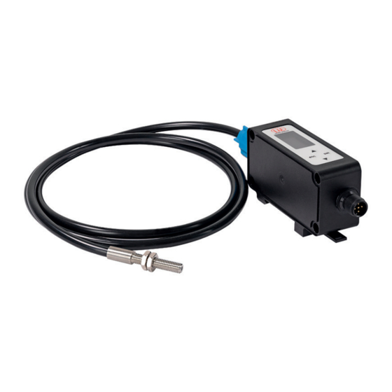
Delivery Delivery Unpacking/Included in Delivery 1 optoCONTROL CLS1000 controller 1 assembly instructions Carefully remove the components of the measuring system from the packaging and ensure that the goods are for- warded in such a way that no damage can occur. -
Page 15: Installation And Assembly
Installation and Mounting Ensure careful handling during installation and operation. During installation of the optoCONTROL CLS1000, ensure that the sensors can be freely moved and are not exposed to any pronounced curvatures or sharp corners. Damage to or destruction and/or failure of the sensor and/or influence on the test result. -
Page 16: Installation Of The Sensor
Take background reflections into account when doing so. Objects in the background can influence the measure- ment; highly glossy surfaces have the greatest effect on the measurement Do not install multiple optical fiber probe heads directly next to one another. > Mutual influence, imprecise measurement values optoCONTROL CLS1000 Page 16... -
Page 17: Installation On A Din Rail
Install Controller 2 to Controller 1 and use M4 hexagon socket screws with the appropriate length to screw the con- troller. IP65 remains intact for the screw connection in the stacked state. Fig. 6 Installation of the CLS1000 on a DIN rail optoCONTROL CLS1000 Page 17... -
Page 18: Control And Display Elements
LED green Supply voltage is active No supply voltage Button for selecting/confirming menu item/value. Deactivate the key lock by pressing for 2 seconds Button to undo the menu selection or go back one menu level; to abort or discard optoCONTROL CLS1000 Page 18... -
Page 19: Electrical Connections Controller
< 50 mA - 4-pin or 5-pin connector (with trigger function) MICRO-EPSILON recommends use of the signal/power supply cable PC1000-5, which is included in the delivery. Perform all electrical connections only in the switched-off state. > Risk of injury from high voltage. -
Page 20: Model Cls1000-Au
The switching behavior (NPN, PNP , push-pull (PP)) of the switching output depends on the programming. Brown 10 V White U Analog Black PP / PNP / NPN Blue Fig. 12 Circuit for switching output CLS1000-AU optoCONTROL CLS1000 Page 20... -
Page 21: Trigger Input Cls1000-Au-Xx-T
Trigger input properties Sensor PC1000-x Comments cable color Blue Ground max. 30 VDC; input current I = < 1 mA Gray Trigger (IN) When wiring the trigger input with an NPN output, an external resistance ≥ 4.7 kΩ ≤ 10 kΩ is necessary. optoCONTROL CLS1000 Page 21... -
Page 22: Model Cls1000-Ai
The switching behavior (NPN, PNP , push-pull (PP)) of the switching output depends on the programming. Brown 20 mA White 0/4 mA U Analog Black PP / PNP / NPN Blue Fig. 17 Circuit for CLS1000-AI optoCONTROL CLS1000 Page 22... -
Page 23: Trigger Input Cls1000-Ai-Xx-T
Trigger input properties Sensor PC1000-x Comments cable color Blue Ground max. 30 VDC; input current I = < 1 mA Gray Trigger (IN) When wiring the trigger input with an NPN output, an external resistance ≥ 4.7 kΩ ≤ 10 kΩ is necessary. optoCONTROL CLS1000 Page 23... -
Page 24: Model Cls1000-Qn
This is often required for detection with wire breakage protection. The PLC always expects an active or passive signal; when this state is not the case, wire breakage or another error is the cause. Brown White PP / PNP / NPN Black PP / PNP / NPN Blue Fig. 21 Circuit for CLS1000-QN optoCONTROL CLS1000 Page 24... -
Page 25: Trigger Input Cls1000-Qn-Xx-T
Trigger input properties Sensor PC1000-x Comments cable color Blue Ground max. 30 VDC; input current I = < 1 mA Gray Trigger (IN) When wiring the trigger input with an NPN output, an external resistance ≥ 4.7 kΩ ≤ 10 kΩ is necessary. optoCONTROL CLS1000 Page 25... -
Page 26: Model Cls1000-2Q
The switching variants of the two switching outputs (PP/PNP/NPN) as well as the switching thresholds can be changed and adjusted individually for Q1 and Q2, respectively, using the operating menu. Brown White PP / PNP / NPN Black PP / PNP / NPN Blue Fig. 25 Circuit for Model CLS1000-2Q optoCONTROL CLS1000 Page 26... -
Page 27: Trigger Input Cls1000-2Q-Xx-T
Trigger input properties Sensor PC1000-x Comments cable color Blue Ground max. 30 VDC; input current I = < 1 mA Gray Trigger (IN) When wiring the trigger input with an NPN output, an external resistance ≥ 4.7 kΩ ≤ 10 kΩ is necessary. optoCONTROL CLS1000 Page 27... -
Page 28: Model Cls1000-Oc
Switching output Q1 OC-openCollector optocoupler OC Maximum switching frequency: 2.5 kHz Switching output Q1 optocoupler OE properties max. 30 VDC; I = 50 mA Black Switching output Q2 OE-openEmitter optocoupler OE Maximum switching frequency: 2.5 kHz optoCONTROL CLS1000 Page 28... -
Page 29: Trigger Input Cls1000-Oc-Xx-T
Trigger input properties Sensor PC1000-x Comments cable color Blue Ground max. 30 VDC; input current I = < 1 mA Gray Trigger (IN) When wiring the trigger input with an NPN output, an external resistance ≥ 4.7 kΩ ≤ 10 kΩ is necessary. optoCONTROL CLS1000 Page 29... -
Page 30: Operation
Operation Operation Initial Operation Install the optoCONTROL CLS1000 controller as per the installation instructions, see 4.1. Connect the controller to the downstream display or monitoring units and to the power supply. The sensor may only be connected to peripherals when it does not carry power, that is, only when the supply voltage has been switched off. -
Page 31: Overview Of Operating Menu
Back to 4230 Back to 4230 SP2 = 0 DOWN without value storage with value storage EXIT Standard display Config. sensor menu with trigger type only Values: available for controller with trigger function SP-2 Value SP1 optoCONTROL CLS1000 Page 31... -
Page 32: Operating Menu
Fig. 31 Legend of the menu structure 5.4.2 Start Starting in the menu structure is identical in all models of the optoCONTROL CLS1000. The most important settings and controller operations can be activated via the keys. The display serves display purposes, see 4.4. -
Page 33: T / Teach-In
Operation 5.4.3 T / Teach-in The Teach-in menu is available in all models of the optoCONTROL CLS1000. Standard Values: Teach-In MENU Standard display AD Value HighSensitiv Values: Standard display AD Value LowSensitiv Values: Standard display AD Value Dark Values: Standard display... -
Page 34: St/ Standard Teach-In
Switching threshold (20 % above the measurement value) = approx. 2500 - In Reflex mode, teach-in is done on a free or very dark background (without a target) - In Transmission mode, teach-in is done on the target to be detected. optoCONTROL CLS1000 Page 34... -
Page 35: Lst / Lowsensitive Teach-In
The analog output is thus also automatically scaled 0 ... 10 V or 0/4 ... 20 mA. Measurement value 0 ... 0.5% of EMR (4095) = approx. 0 Switching threshold 20 % above the measurement value (4095) = approx. 800 optoCONTROL CLS1000 Page 35... -
Page 36: Ppt / Peaktopeak Teach-In
5.4.3.7 PPT / PeakToPeak Teach-in In PeakToPeak teach-in mode (PPT), the optoCONTROL CLS1000 controller is placed in a recording mode that enables automatic teach-in. After the recording mode ends, a switching point is calculated between the minimum and maximum measurement values. The mode can be used for running (cyclical) processes, such as detection of saw tooth sheets, turbine blades and gaps. -
Page 37: Q1 / Config Q1
Operation 5.4.4 Q1 / Config Q1 The Q1 menu for the switching output Q1 is available in all models of the optoCONTROL CLS1000. Config Q1 Switching polarity Values: MENU - L-SW: Light switching - D-SW: Dark switching Value Output type... -
Page 38: Ana / Config Ao
Operation 5.4.5 ANA / Config AO The ANA menu is only available in the optoCONTROL CLS1000-AU and -AI models. Output type 1 Values: - 0-20: Current output 0 ... 20 mA TYPE - 4-20: Current output TYPE Value 4 ... 20 mA... -
Page 39: Signal Spread Display Value And Analog Output
Meas. value Up / Back to 4230 Back to 4230 SP1 = 0 DOWN without value storage with value storage Values: SP-1 Value SP1 Fig. 37 ANA / Config AO / SPRD - Spread point 1 menu optoCONTROL CLS1000 Page 39... - Page 40 Set the ones position with The set value is applied as SP2, the factor is determined. If you need 2 spread points, the automatic spread is finished. Press the esc key multiple times to return to the standard view. optoCONTROL CLS1000 Page 40...
-
Page 41: Sen / Config Sensor
Spread value = If MV ≤ SP1; then EMR; otherwise, if MV > SP2; then 0; otherwise, (MV + Offset-EMR) * factor) MV = measurement value EMR = end of measuring range 5.4.6 SEN / Config Sensor The SEN menu is only available in optoCONTROL CLS1000 models with trigger function. Config Sensor Values: -OFF: No ext. trigger Trigger type... -
Page 42: Rst / Factory Settings
Operation 5.4.8 RST / Factory settings The RST menu is available in all models of the optoCONTROL CLS1000. Factory settings Confirmation MENU Confirmation Reset parameters Standard display to factory settings Fig. 41 RST / Factory settings menu 5.4.9 EXIT / Exit (Lock) The EXIT menu is available in all models of the optoCONTROL CLS1000. -
Page 43: Functions
Parameterization/operation via membrane keyboard and Operating menu , see 5.4.6 ; indicated via display on controller. Parameterization Parameterization is done via the membrane keyboard and Operating menu All menus see 5.3 ; indicated via display on controller.. optoCONTROL CLS1000 Page 43... - Page 44 The sensor can be triggered via Pin 5 in the trigger versions. Operation via membrane keyboard and Operating menu , see 5.4.6 indicated via display on controller. WatchDog Restart in case of error. In the event of a controller error, the controller restarts (Error recovery). optoCONTROL CLS1000 Page 44...
-
Page 45: Cleaning
MICRO-EPSILON or to your distributor / retailer. MICRO-EPSILON undertakes no liability whatsoever for damage, loss or costs caused by or related in any way to the product, in particular consequential damage, e.g., due to... -
Page 46: Decommissioning, Disposal
- A list of national laws and contacts in the EU member states can be found at https://ec.europa.eu/environment/topics/waste-and-recycling/waste-electrical-and-electronic-equipment-weee_en. Here you can inform yourself about the respective national collection and return points. - Old devices can also be returned for disposal to MICRO-EPSILON at the address given in the imprint at https://www. micro-epsilon.com/impressum/. -
Page 47: Appendix
Other lengths and/or 90° angled are also possible on request. Name Photo Description Article number Sensors (optical fiber) CFS4-C20-P-600 Reflected-light optical fiber 10810373 CFS3-A20-P Transmitted-light optical fiber 10810322 You can find additional sensors (optical fibers) in the optoCONTROL CLS-K catalog optoCONTROL CLS1000 Page 47... -
Page 48: A 2 Factory Settings
2m-PVC; Terminal-2P-BU-ge PS2020 Power supply for DIN rail installation, 2420062 input 230 VAC, output 24 VDC/2.5 A Factory Settings You can use the RST menu in the Operating menu, see 5.4.8, to reset to factory settings. optoCONTROL CLS1000 Page 48... -
Page 49: A 3 Circuit Examples
Setting: Switching behavior = PNP V switching Brown White Black Blue Fig. 44 Circuit = PNP V switching Setting: Switching behavior = NPN GND switching Brown White Black Blue Fig. 45 Circuit = NPN GND switching optoCONTROL CLS1000 Page 49... -
Page 50: A 3.2 Cls1000-Ok
Switching behavior Q = PNP V switching Circuit for switching behavior PP , NPN as for CLS1000-QN and CLS1000-2Q Brown 10 V White Black i ≥ 10 kΩ Blue Fig. 48 Circuit Q = PNP V switching optoCONTROL CLS1000 Page 50... -
Page 51: A 3.4 Cls1000-Ai
Fig. 50 Circuit for trigger input CLS1000-xx-T - PP or PNP When wiring the trigger input with an NPN output, an external resistance ≥ 4.7 kΩ ≤ 10 kΩ is necessary. Brown external 10 kΩ Gray Blue Fig. 51 Circuit for trigger input CLS1000-xxT - NPN optoCONTROL CLS1000 Page 51... - Page 52 MICRO-EPSILON Eltrotec GmbH Manfred-Wörner-Straße 101 · 73037 Göppingen / Germany Tel. +49 (0) 7161/98872-300 · Fax +49 (0) 7161/98872-303 X9751442-A012062DTa eltrotec@micro-epsilon.com · www.micro-epsilon.com Your local contact: www.micro-epsilon.com/contact/worldwide/ MICRO-EPSILON MESSTECHNIK...
Need help?
Do you have a question about the optoCONTROL CLS1000 and is the answer not in the manual?
Questions and answers