Table of Contents
Advertisement
Quick Links
Advertisement
Chapters
Table of Contents

Subscribe to Our Youtube Channel
Related Manuals for Omron L


Summary of Contents for Omron L
- Page 1 Cat. No. Z197-E1-02A ZX-L-N Series Smart Sensors Laser Type USER’S MANUAL...
- Page 2 APPLICATION CONSIDERATIONS (Please Read) Introduction FEATURES Section PREPARATION FOR MEASUREMENT Section BASIC OPERATION Section MAIN APPLICATIONS AND SETTING METHODS Section DETAILED SETTINGS Section AUXILIARY FUNCTIONS Section APPENDIX Section User’s Manual Smart Sensors ZX-L-N Series...
- Page 3 • The ZX-L-N Smart Sensor must be operated by personnel knowledgeable in electrical engineering. • To ensure correct use, please read this manual thoroughly to deepen your understanding of the product. • Please keep this manual in a safe place so that it can be referred to whenever necessary. ZX-L-N User’s Manual...
- Page 4 The following are some examples of applications for which particular attention must be given. This is not intended to be an exhaustive list of all possible uses of the products, nor is it intended to imply that the uses listed may be suitable...
- Page 5 This document shall not be copied for sales or promotions without permission. This document is protected by copyright and is intended solely for use in conjunction with the product. Please notify us before copying or reproducing this document in any manner, for any other purpose. If copying or transmitting this document to another, please copy or transmit it in its entirety.
- Page 6 The following signal words are used in this manual. Indicates a potentially hazardous situation which, if not avoided, will result in minor or moderate injury, or may result in serious injury or death. Additionally there may be significant property damage.
- Page 7 Never look into the laser beam. Doing so continuously will result in visual impairment. Do not disassemble the product. Doing so may cause the laser beam to leak, resulting in the danger of visual impairment. ZX-LT Through-beam Type Sensor Head Do not look into the laser beam.
- Page 8 FDA (21 CFR1040.10) (see note). The ZXLT Sensor Heads are Class 1 and Class II Laser Products, respectively. The ZX Series is meant to be built into final system equipment. Pay special attention to the following precautions for the safe use of...
-
Page 9: Precautions For Safe Use
Please observe the following precautions for safe use of the products. Installation Environment • Do not use the product in environments where it can be exposed to inflammable/ explosive gas. • Do not install the product close to high-voltage devices and power devices in order to secure the safety of operation and maintenance. -
Page 10: Precautions For Correct Use
• If surge currents are present in the power lines, connect surge absorbers that suit the operating environment. • When using two ore more amplifier units, make sure that the linear GND line of the amplifier units are connected to each other. -
Page 11: Maintenance And Inspection
If large dust particles adhere to the front filter of the sensor head, use a blower brush (used to clean camera lenses) to blow them off. Do not blow the dust away with your mouth. To remove smaller dust particles, use a soft cloth (for lenses) with a small amount of alcohol. -
Page 12: Page Format
Shows the display status resulting from the operation. Keys or switches to be used Illustrates the keys and switches to be used. Operation procedure and supplementary explanation Explains the operation procedure and the display status resulting from execution of the operation. -
Page 13: Operation Procedure
Introduction Notational Conventions Menu In this manual, menu items displayed on the screen are enclosed with [ ]. Operation procedure Operation steps are numbered to indicate their order. Visual Aids Indicates points that are important to achieve the full product performance, such as operational precautions and application procedures. -
Page 14: Table Of Contents
Precautions for Safe Use viii Precautions for Correct Use Editor's Note Contents xiii Section 1 FEATURES ZX-L Features Section 2 PREPARATION FOR MEASUREMENT Basic Configuration Part Names and Functions Installing the Amplifier Unit Installing Sensor Heads Connections Wiring Input/Output Cables ZX-L-N xiii User’s Manual... - Page 15 Flow of Operation Basic Knowledge for Operation Function Transition Charts Setting the Auto Scale Setting the Standard Received Light Amount Measuring the Received Light Amount (Intensity Mode) Section 4 MAIN APPLICATIONS AND SETTING METHODS Measuring Height Measuring Thickness Measuring Eccentricity and Vibration...
- Page 16 Initializing Settings Data Section 7 APPENDIX Troubleshooting Error Messages and Countermeasures Q&A Glossary Specifications and Dimensions Communication with the Smart Monitor is possible via the Interface Unit Engineering Data Quick Reference for Displays Requirements from Regulations and Standards Index Revision History ZX-L-N...
- Page 17 Introduction MEMO ZX-L-N User’s Manual...
-
Page 18: Section 1 Features
Section 1 FEATURES ZX-L Features ZX-L-N User’s Manual... -
Page 19: Zx-L Features
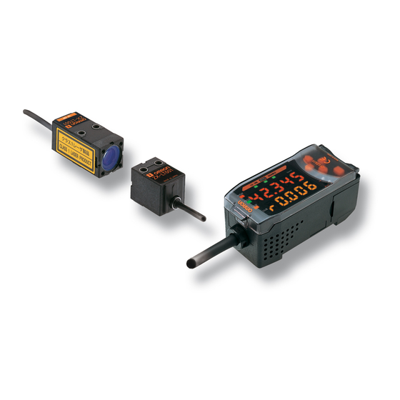
The ZX-L Series provide the reflective type for displacement measurement and through-beam type for smart length measurement. Measurement is performed using laser. By irradiating laser beams to the object, the sensor can measure the distance between the object and sensor head, perform positioning and width judgement. - Page 20 Many, Simple Functions Measurement Ready at Power ON The sensor can be used simply by installing and wiring it. Simply turn ON the power and it is ready to operate. The measurement results are displayed on the Amplifier Unit.
- Page 21 Mutual Interference Prevention for Closely Mounted Sensor Heads The sensor has a mutual interference prevention function which allows multiple Sensor Heads to be mounted close to each other. This function is supported for up to two Sensor Heads by using ZX-CAL2 Calculating Units. p.24 Calculating...
- Page 22 FEATURES Compatibility between Sensor Heads and Amplifier Units Amplifier Units do not need to be changed when Sensor Heads are changed for maintenance or to switch to new products. Extendable Sensor Head Cables Special extension cables are provided to extend sensor heads.
- Page 23 Resolution Confirm Measurement Status on a Personal Computer Use an Interface Unit and Smart Monitor to view measurement waveforms and log measurement data on a personal computer. This function is useful for making on-site measurement adjustments and for day-to-day quality control.
- Page 24 Built-in Laser Life Monitor When the laser of Sensor Head deteriorates, [LDDWN] will appear for approx. five seconds on the Main Display when the power is turned ON. This assists in understanding when the Sensor Head should be replaced with a new one.
- Page 25 Section 1 FEATURES MEMO ZX-L-N User’s Manual...
-
Page 26: Section 2 Preparation For Measurement
Section 2 PREPARATION FOR MEASUREMENT Basic Configuration Part Names and Functions Installing the Amplifier Unit Installing Sensor Heads Connections Wiring Input/Output Cables ZX-L-N User’s Manual... -
Page 27: Basic Configuration
Basic Configuration The basic configuration of the ZX-L series Smart Sensors is shown below. ZX-L series Smart Sensors are not compatible with other ZX series Smart Sensors. ZX-L cannot be used with ZX-E, ZX-W and ZX-T series Smart Sensors. Basic Configuration... -
Page 28: Part Names And Functions
(12) The sub-display shows additional information and function settings for measurements. Reading Displays p.35 (13) The threshold switch selects whether to set (and display) the HIGH or LOW threshold. (14) The mode switch selects the operating mode. Switching Modes p.34 (15) The Control Keys set measurement conditions and make other settings. -
Page 29: Sensor Head
FAR Indicator Both NEAR and FAR indicators are lit: Measuring center distance (Measuring range x 10%) NEAR indicator is lit: Near side within measuring range FAR indicator is lit: Far side within measuring range Both NEAR and FAR indicators are blinking:... - Page 30 Connector Connector Sensor Head – Amplifier Unit Sensor Head – Amplifier Unit To be connected to the connecting cable. To be connected to the connecting cable. Connector Connector To be connected to the receiver. To be connected to the emitter.
- Page 31 Section 2 PREPARATION FOR MEASUREMENT Calculating Units Display (*) Connector (two connectors, one on each side) To be connected to the Amplifier Unit. * Display Detail Connection indicator Lit when the Amplifier Unit is connected. ZX-L-N User’s Manual...
- Page 32 (3) The power supply indicator lights while the power is supplied. (4) BUSY: Lights during communications with the Smart Sensor. ERR: Lights if an error occurs during communications with the Smart Sensor. (5) BUSY: Lights during communications with the personal computer.
-
Page 33: Installing The Amplifier Unit
PFP-100N2 (1m) End Plate (Option) PFP-M Installation Hook the connector end of the Amplifier Unit on the DIN Track and press in at the bottom until the Unit locks into place. Hook on the connector end Always hook the connector end of the Amplifier Unit on the DIN Track first. Mounting strength may decrease if the output cable end is hooked on the DIN Track first. - Page 34 Section 2 PREPARATION FOR MEASUREMENT Removal Method Push the Amplifier Unit up and pull out from the connector end. ZX-L-N User’s Manual...
-
Page 35: Installing Sensor Heads
Mounting dimensional drawing (for M4 screws) (Unit: mm) 47±0.1 2-M4 When mounting a Sensor Head, take care not to touch the emitter and receiver. Adhesion of finger marks may hinder correct measurements. If you have touched them, wipe them with a clean, soft cloth. - Page 36 ZX-LT010 Mounting dimensional drawing (same for both emitter and receiver) (Unit: mm) 2-M3 Make sure that the emitter and receiver are mounted in the correct direction as shown below. Mounting them in the wrong direction will hinder correct measurements. Mounting hole...
-
Page 37: Adjusting The Optical Axis
Optical axis adjustment seal • When adjusting the receiver position, take care not to touch the emitter and receiver of the sensor head. Adhesion of finger marks may hinder correct measurements. If you have touched them, wipe them with a clean, soft cloth. -
Page 38: Connections
This section describes how to connect component parts of the Smart Sensor. Before connecting/disconnecting Smart Sensor components, make sure that the power to the Amplifier Unit is turned OFF. The Smart Sensor may malfunction if components are connected or removed while the power is ON. - Page 39 To disconnect the Reflective Type Sensor Head, hold the Sensor Head's connector ring and the Amplifier Unit connector, and then pull them straight out. • Make sure to hold the connector of the Amplifier Unit to disconnect it. Failure to do so may damage the input cable of the Amplifier Unit.
- Page 40 Section 2 PREPARATION FOR MEASUREMENT Unhook the connector of the Sensor Head – Amplifier Unit cable from the emitter and receiver connectors, and pull them straight out as shown below. Hook ZX-L-N User’s Manual...
- Page 41 Sensor Heads or connect ZX-SF11 to perform communication between Amplifier Units, use a Calculating Unit to connect the Amplifier Units. The number of Amplifier Units that can be joined depends on the functions being used. Functions No. of Connectable Amplifier Units Calculation Max.
- Page 42 Section 2 PREPARATION FOR MEASUREMENT Channel Numbers of Amplifier Units The following diagram shows the channel numbers when multiple Amplifier Units are connected. ZX-L-N User’s Manual...
- Page 43 Slide and connect the Interface Unit to the Amplifier Unit connector. To disconnect the Interface Unit, perform the above operations in reverse order. • When multiple Amplifier Units are used, connect the Interface Unit to the Amplifier Unit with the highest channel number.
-
Page 44: Wiring Input/Output Cables
Amplifier Unit, particularly when high resolution is required. (2) The GND terminal is the 0-V power supply terminal. When using an Amplifier Unit with an NPN output, the GND terminal is also the common I/O terminal for all I/O except for the linear output. -
Page 45: I/O Circuit Diagrams
Purple Timing input Orange Zero reset input Reset input Current output 4 to 20mA Current/voltage Black Linear output output Switch Current output: 300Ω or lower Voltage 100Ω Load ±4V Voltage output: 10kΩ or higher Shield Linear GND ZX-L-N User’s Manual... - Page 46 Purple Timing input Orange Zero reset input Reset input Current output 4 to 20mA Current/voltage Black Linear output output Switch Current output: 300Ω or lower Voltage 100Ω Load Voltage output: 10kΩ or higher ±4V Shield Linear GND ZX-L-N User’s Manual...
- Page 47 Section 2 PREPARATION FOR MEASUREMENT MEMO ZX-L-N User’s Manual...
-
Page 48: Section 3 Basic Operation
Switching Modes Reading Displays Key Operations Condition Settings Inputting Numeric Values Function Transition Charts RUN Mode T Mode FUN mode Setting the Auto Scale Setting the Standard Received Light Amount Measuring the Received Light Amount (Intensity Mode) ZX-L-N User’s Manual... -
Page 49: Flow Of Operation
Preparation for Preparation for Measurement Measurement Turn ON the power. Turn ON the power. Select the display unit (% or mm) and the item to be measured (received or blocked light amount). p.42 Setting the Auto Scale (Not necessary if the two-point... - Page 50 Section 3 BASIC OPERATION When a Problem Occurs…. The Smart Sensor Does Not An Error Message Has Appeared Operate Correctly Error Messages and p.127 p.126 Troubleshooting Countermeasures Want to Know Meanings of Want to Find Contents from Terms Digital Displays p.130...
-
Page 51: Basic Knowledge For Operation
Section 3 BASIC OPERATION Basic Knowledge for Operation Switching Modes The ZX-L has three modes. Use the Mode Switch on the Amplifier Unit to switch between modes. Switch to the desired mode before starting operation. LD ON Mode Description Normal operation mode... -
Page 52: Reading Displays
The data displayed on the main and sub-displays depends on the mode currently selected. RUN mode has been selected prior to shipment from the factory. When the power is turned ON, the type of amplifier unit and then the number of channels will be displayed on the main display. -
Page 53: Key Operations
Section 3 BASIC OPERATION Alphabet Display Format The alphabet appears on the main and sub-displays as shown in the following table. A B C D E F G H I J K L M N O P Q R S T U V W X Y Z Key Operations Use the Control Keys to change the display and set measurement conditions. LD ON Control Keys The mode currently selected determines the key functions. -
Page 54: Condition Settings
Display the target function on the main display and select the desired value from the sub-display to set measurement conditions. This section uses the example of setting a peak hold as the hold condition to explain how to set measurement conditions. -
Page 55: Inputting Numeric Values
Section 3 BASIC OPERATION Inputting Numeric Values This section describes how to input numeric values for threshold and output settings. The example of direct input of the low threshold value will be used. Changing the low threshold from 40,000 to 39,000 Moving to T Mode Set the mode switch to T. -
Page 56: Function Transition Charts
The numerals shown in the above diagram are an example only. The actual display may be different. In RUN and T modes, the position of the threshold switch will determine whether the HIGH or LOW threshold will be displayed. Threshold switch... -
Page 57: Fun Mode
Displayed only when the p.76 connected sensor head is the Through-beam type. selected, will be displayed again without special functions displayed. p.42 If the connected sensor head is the Through-beam type, will be displayed. Special functions Previous value Linear output Differentiation Intensity mode... - Page 58 Displayed on non-CH1 Amplifier Units if two or more Amplifier Units are connected. This symbol requests you to move to another menu using the LEFT or RIGHT Key after pressing the ENT Key to confirm the selections. ZX-L-N User’s Manual...
-
Page 59: Setting The Auto Scale
The auto scale function allows you to select whether the received light amount is to be displayed in mm or in % in the main display. It also allows you to select whether the received light amount or blocked light amount is to be displayed. - Page 60 • The default setting at shipment is 100-L. • If you want to display the received light amount in a width other than “0 to 5mm”, “0 to 10mm” and “0 to 30mm”, the two-point scaling function must be used.
- Page 61 Section 3 BASIC OPERATION Moving to FUN Mode and AUTOS Set the mode switch to FUN. Use the LEFT and RIGHT Keys to display LD ON ZERO ENABLE [AUTOS] on the main display. (mm) Setting the Auto Scale Press the UP or DOWN Key.
-
Page 62: Setting The Standard Received Light Amount
[SETST] is displayed in the sub-display. • Setting of the standard received light amount must be carried out while zero reset is not in progress (i.e. while the zero reset indicator is not lit). • When the standard received light amount is set, the main display and linear outputs (current, voltage) will be set to the full scale (F.S.) automatically. -
Page 63: Measuring The Received Light Amount (Intensity Mode)
• With the intensity mode, all processing, including 2-sensor operation, hold, threshold judgement and linear outputs, will be performed on the received light amount. • To use intensity mode, intensity mode must be set first. When intensity mode is set, some settings (e.g. monitor focusing) are initialized. - Page 64 Switching to Intensity Mode Press the UP or DOWN Key. The sub-display will flash. Use the UP and DOWN Keys to display [ON]. Press the ENT Key to confirm the setting. The Sensor Head will be set to intensity mode.
- Page 65 Section 3 BASIC OPERATION MEMO ZX-L-N User’s Manual...
-
Page 66: Section 4 Main Applications And Setting Methods
Section 4 MAIN APPLICATIONS AND SETTING METHODS Measuring Height Measuring Thickness Measuring Eccentricity and Vibration Measuring Edges ZX-L-N User’s Manual... -
Page 67: Measuring Height
Section 4 MAIN APPLICATIONS AND SETTING METHODS Measuring Height This section describes how to measure the height of an object, using a PCB mold as an example. Mold Flow of Operation Place an actual sensing object in position. Have a reference sample ready beforehand. - Page 68 Place the reference sample in position and adjust the Sensor Head position. Refer to the Amplifier Unit's display or Sensor Head's indicators, and adjust the Sensor Head position so that the upper and lower limits of the height (H) to be measured fall within the measuring range.
- Page 69 When the timing signal cannot be input from the device, set a self-down trigger. Measured value Self-trigger level The bottom value is held. Sampling The following settings are required when the reference sample height is displayed using the scaling function: Measurement trigger: Self-up trigger Hold condition: Peak hold Refer to Section 5 Detailed Settings for details on settings.
- Page 70 Refer to the HIGH threshold registered in step and set the upper and lower limits (HIGH and LOW thresholds) for a PASS (OK) judgement. The HIGH, PASS, and LOW judgement results will be output based on the threshold values set here. Measurement Result Judgement Measurement result >...
-
Page 71: Measuring Thickness
Section 4 MAIN APPLICATIONS AND SETTING METHODS Measuring Thickness This section describes how to measure thickness, using the thickness of a steel plate as an example. Steel plate Flow of Operation Setting Tolerance Mounting to Adjusting Setting Setting Judgement Device... - Page 72 If the Amplifier Units are connected, mutual interference between the Sensor Heads can also be prevented. Mounting Sensor Heads to Inspection Device Mount the Sensor Heads to the steel plate in such a way that they face each other as shown below. Installing Sensor Heads p.18...
- Page 73 Adjusting Setting Distances Set a reference sample with a known thickness (T). Adjust the position of the Sensor Heads so that the distances (A, B) between the reference sample and the Sensor Heads are about the measuring center distance of the corresponding Sensor Head.
- Page 74 MAIN APPLICATIONS AND SETTING METHODS Setting Tolerance Judgement Values Set the upper and lower limits (HIGH and LOW thresholds) for the thickness for a PASS (OK) judgement. The HIGH, PASS, and LOW judgement results will be output based on the threshold values set here.
-
Page 75: Measuring Eccentricity And Vibration
Section 4 MAIN APPLICATIONS AND SETTING METHODS Measuring Eccentricity and Vibration This section describes, as an example, how to measure the eccentricity of a motor shaft. Motor shaft Flow of Operation Setting Tolerance Mounting to Measuring Adjusting Setting Judgement Device... - Page 76 Section 4 MAIN APPLICATIONS AND SETTING METHODS Mounting to Device Mount the Sensor Head to the inspection device. When mounting the sensor, take care not to exert pressure on the sensor head and wires. Installing Sensor Heads p.18 Adjusting Setting Position...
- Page 77 MAIN APPLICATIONS AND SETTING METHODS Measuring Deflection Use the peak-to-peak hold function to measure the normal deflection. Rotate the motor shaft, input a timing signal from an external device, and measure the deflection. The difference between the maximum and minimum measurement results (the deflection) will be used as a reference when setting tolerances.
-
Page 78: Measuring Edges
Section 4 MAIN APPLICATIONS AND SETTING METHODS Measuring Edges This section describes, as an example, how to measure the edges of a rubber sheet. Rubber sheet Flow of Operation Measuring Setting Tolerance Setting the Mounting to Setting Auto Judgement Standard Received... - Page 79 Installing Sensor Heads p.18 Setting Auto Scale Decide whether to display the received light amount in mm or in % in the Amplifier Unit's main display. Setting the Auto Scale p.42 Example: To display 5mm as the current input light amount (85%) Before auto scale is set Auto scale is set to [5-L].
- Page 80 Refer to the HIGH threshold registered in step and set the upper and lower limits (HIGH and LOW thresholds) for a PASS (OK) judgement. The HIGH, PASS, and LOW judgement results will be output based on the threshold values set here. Measurement Result Judgement Measurement result >...
- Page 81 Section 4 MAIN APPLICATIONS AND SETTING METHODS MEMO ZX-L-N User’s Manual...
-
Page 82: Section 5 Detailed Settings
Section 5 DETAILED SETTINGS Setting Number of Samples to Average Changing Display Scales Setting the Measurement Sensitivity (Gain Switching) Using Hold Functions Comparing Measured Values (Differentiation Function) Comparing Measured Values (Previous Value Comparisons) Entering Threshold Values Linear Output Setting Judgement Output Timing (Timer) ZX-L-N User’s Manual... -
Page 83: Detailed Settings
DETAILED SETTINGS Setting Number of Samples to Average The average of the measured values obtained based on the preset number of samples can be output. This setting can be used when you want to ignore rapid changes in measured values. -
Page 84: Changing Display Scales
• The scaling set here is reflected in the display only. If you want to change the linear output of the displayed value, the monitor focus function must be used. The minimum display value is -19999, and the maximum display value is 59999. Values (scaling correction values) that exceed the minimum or maximum display value even if the object is located within the measuring range cannot be set. - Page 85 Actual distance: 8mm (mm) Displayed value: 7mm The settings listed below return to the default settings when scaling is set. Make the settings for these items after scaling settings have been completed. Self-trigger level, p.78 Monitor focus p.95 Zero Reset, p.116 Thickness setting (calculation) p.108...
- Page 86 Section 5 DETAILED SETTINGS One-point Scaling Measurement is performed at one position and offset values are set for that measurement. The offset and increment/decrement inversion (display inversion) can be set. This section describes how to set one-point scaling, using an example of correcting display values to match actual distances.
- Page 87 Set the sensing object at the position where the display value change is required. Set the sensing object within the measurement distance. The ENABLE indicator will be lit when the sensing object is within the measurement distance. Scaling is not possible if the sensing object is not within the distance.
- Page 88 If scaling has been completed correctly, the display will LD ON ZERO ENABLE be [OK]. (mm) If scaling was unable to be completed, the display will be LD ON ZERO ENABLE [NG]. (mm) Check that the sensing object is within the measurement range and execute scaling again.
- Page 89 Displayed value: 33mm Sensing object Separate the two specified points by at least 1% of the rated measurement range for the connected Sensor. For example, the rated measurement range for the ZX-LD40 Sensor is 20 mm. Therefore, the two specified points must be separated by 0.2 mm min.
- Page 90 Section 5 DETAILED SETTINGS Setting the Second Point Place the sensing object in the position for which the display is to be changed (the second point). The sensing object must be set at a distance at least 1% of the rated measurement range away from the first point and also at a distance within the measurement range.
-
Page 91: Setting The Measurement Sensitivity (Gain Switching)
[E-BRT].) [E-DRK].) AUTO can be set only when the Sensor Head is the Reflective type and the intensity mode is disabled. Intensity mode p.46 Moving to FUN Mode and SPCL Set the mode switch to FUN. Use the LEFT and RIGHT Keys to display... - Page 92 DETAILED SETTINGS Moving to GAIN Press the UP or DOWN Key. The sub-display will flash. Use the UP and DOWN Keys to display [ETC] or [ALL]. Press the ENT Key. Use the LEFT and RIGHT Keys to display LD ON...
-
Page 93: Using Hold Functions
The value to be held during that sampling period is selected here. The CLAMP value is output until the first sampling period is finished. CLAMP value p.102 Any of the 5 settings shown in the table can be selected as the value to hold. Selection Details Hold measurement is not performed. - Page 94 Sampling period S-H (Sample hold) Holds the measured value at the start of the sampling period. The output changes at the start of the sampling period and is held until the start of the next sampling period. Output Current...
- Page 95 • Zero reset input will be invalid during sampling or while [-----] is displayed in the main display. • The timing input signal will be ignored if the self-trigger level is set to [UP] or [DOWN]. However, sampling will not be affected.
- Page 96 ZERO ENABLE [H-LVL] on the main display. (mm) [H-LVL] will not be displayed if timing input [TIMIG] is set as the trigger. Press the UP or DOWN Key. The leftmost digit of the sub-display will flash. Use the Cursor Keys to set the desired trigger Moves from one digit to level.
- Page 97 ZERO ENABLE [H-HYS] on the main display. (mm) [H-HYS] will not be displayed if timing input [TIMIG] is set as the trigger. Press the UP or DOWN Key. The leftmost digit of the sub-display will flash. Use the Cursor Keys to set the hysteresis Moves from one digit to width for the trigger level.
- Page 98 The default delay time setting is [OFF]. Make the sum of the delay time and sampling period less than the timing input ON interval. If the next timing input for measurement is received before the delay and sampling period have passed, that timing input will be ignored and will not be reflected in the sampling.
- Page 99 ZERO ENABLE [H-D-T] on the main display. (mm) [H-D-T] will not be displayed if the H-DLY function is set to [OFF]. Press the UP or DOWN Key. The leftmost digit of the sub-display will flash. Enter the delay time (ms).
-
Page 100: Comparing Measured Values (Previous Value Comparisons)
The differentiation function detects changes between the present value and the measured value that is in effect just before the comparing pitch. The coefficient of this comparing pitch is defined as the differentiation cycle. - Page 101 DETAILED SETTINGS Moving to DIFF Press the UP or DOWN Key. The sub-display will flash. Use the UP and DOWN Keys to display [SET] or [ALL]. Press the ENT Key. Use the LEFT and RIGHT Keys to display LD ON...
- Page 102 ENABLE [D-CYC] on the main display. (mm) [D-CYC] will not be displayed if the DIFF is set to OFF. Press the UP or DOWN Key. The leftmost digit of the sub-display will flash. Use the Cursor Keys to set the differentiation Moves from one digit to cycle.
-
Page 103: Comparing Measured Values (Previous Value Comparisons)
Comparisons) Use the previous value comparison function to ignore gradual changes in measured values over time, due to factors such as temperature drift, and only detect and judge sudden changes. The hold function must be set before previous value comparison can be set. The difference from the previous hold value with a PASS judgement becomes the measured value. - Page 104 DETAILED SETTINGS Moving to COMP Press the UP or DOWN Key. The sub-display will flash. Use the UP and DOWN Keys to display [SET] or [ALL]. Press the ENT Key. Use the LEFT and RIGHT Keys to display LD ON...
-
Page 105: Entering Threshold Values
Section 5 DETAILED SETTINGS Entering Threshold Values Threshold values are set to determine the range for PASS judgements. Both HIGH and LOW threshold values are set. There are three judgement outputs: HIGH, PASS and LOW. HIGH threshold Measured value LOW threshold (ON when Measurement result >... - Page 106 Inputting Threshold Values Directly The threshold values can be set by directly inputting the numeric values. Direct input is useful when you know the dimensions for an OK judgement or when you want to fine-tune threshold values after teaching. Moving to T Mode Set the mode switch to T.
- Page 107 Threshold HIGH threshold (Upper limit) sample (Lower limit) Hold, trigger mode, and scaling settings that have been made before teaching are reflected in the teaching measurements. Moving to T Mode Set the mode switch to T. Setting Threshold Values Move the threshold switch to either H or L,...
- Page 108 The threshold can be calculated by the following equation. Threshold = (Teaching point A + Teaching point B) / 2 Hold, trigger mode, and scaling settings that have been made before teaching are reflected in the teaching measurements. Setting Teaching point A Set the teaching point A by following steps of the position teaching procedure.
- Page 109 Moving to T Mode Set the mode switch to T. Start the device. The threshold switch can be set to either position. Both HIGH and LOW thresholds will be set, regardless of the switch setting. ZX-L-N User’s Manual...
- Page 110 When ERRLH is displayed p.89 The threshold values set using automatic teaching can be changed using direct input. This is useful when setting judgement tolerances for measured values. p.89 ZX-L-N User’s Manual...
-
Page 111: Hysteresis Setting
Section 5 DETAILED SETTINGS Hysteresis Setting Set the hysteresis width for the upper and lower limits of judgements if the HIGH, PASS, or LOW judgement is unstable near the threshold values. Hysteresis (hysteresis width) HIGH threshold Measured value Operation point... -
Page 112: Linear Output
(mm) (mm) Separate the two specified points by at least 1% of the rated measurement range for the connected Sensor. For example, the rated measurement range for the ZX-LD40 Sensor is 20mm. Therefore, the two specified points must be separated by 0.2mm min. - Page 113 This section describes how to set the output range, using an example of current output with a range with the following conversions: 35mm to 4 mA and 45mm to 20 mA. Change the values in this example for voltage output as necessary.
- Page 114 Set a measured value within the measurement distance. If scaling or calculation has been set, set a value that reflects those settings. The flashing digit, i.e., the digit for which a value can be set, will change as shown in the diagram. LD ON ZERO...
- Page 115 Press the ENT Key to confirm the setting. LD ON ZERO ENABLE (mm) Confirming Completion of Monitor Focus Settings The display will read [OK] if monitor focus has been set LD ON ZERO ENABLE correctly. (mm) If not, the display will show [NG].
- Page 116 Set the monitor focus function and select either current or voltage output beforehand. p.95 This section uses a current output as an example. Change the values in this example for voltage output as necessary. Connect the linear output to an external ammeter.
- Page 117 If the correction value changes by 4, the linear output will change by approx. 1.4µA(0.7mV). The flashing digit, i.e., the digit for which a value can be set, will change as shown in the diagram. LD ON ZERO...
- Page 118 Section 5 DETAILED SETTINGS Press the ENT Key to confirm the setting. The correction value for the first point will be confirmed. The screen for setting the second point correction value will be displayed. Setting the Second Point (B) Use the same procedure as the first point to...
- Page 119 (approx. 5.5V) • For Hold Measurements Even if [KEEP] is set, the output before the first hold value is obtained will be the same as CLAMP. • Even in FUN mode, the outputs will be made according to the non-measurement settings.
- Page 120 Selecting Output Status for Non-measurement Press the UP or DOWN Key. The sub-display will flash. Use the UP and DOWN Keys to select either [KEEP] or [CLAMP]. Press the ENT Key to confirm the setting. The setting will be registered.
-
Page 121: Setting Judgement Output Timing (Timer)
Section 5 DETAILED SETTINGS Setting Judgement Output Timing (Timer) The timing for judgement outputs can be adjusted to match the operation of external devices. Selection Details Outputs the judgement as soon as the Measured value judgement result has been confirmed. - Page 122 Section 5 DETAILED SETTINGS The following description uses the OFF-delay timer as an example. Make the necessary adjustments if other timers are used. Moving to FUN mode and TIMER Set the mode switch to FUN. Use the LEFT and RIGHT Keys to display...
- Page 123 Section 5 DETAILED SETTINGS Press the UP or DOWN Key. The leftmost digit of the sub-display will flash. Use the Cursor Keys to set the timer time Moves from one digit to (ms). another. Changes the current value. Press the ENT Key to confirm the setting.
-
Page 124: Section 6 Auxiliary Functions
Section 6 AUXILIARY FUNCTIONS Measuring with Multiple Amplifier Units Changing the Number of Display Digits Reversing the Display Adjusting Display Brightness (ECO Display) Using the Zero Reset Function Key Lock Function Initializing Settings Data ZX-L-N User’s Manual... -
Page 125: Measuring With Multiple Amplifier Units
2Finds the thickness of a sensing object clamped between two Sensor Heads. The response time of the CH2 Amplifier Unit to which an expression is set will be prolonged by 1.0ms. Since the response time is influenced by the number of samples to average, the actual response time will be “response time based on the number of samples to average + 1.0ms”. - Page 126 Section 6 AUXILIARY FUNCTIONS Adding and Subtracting Measurement Results The expression A+B or A-B is used. All settings are made on the CH2 Amplifier Unit. Moving to FUN and CALC Set the mode switch to FUN on the CH2 Amplifier Unit.
- Page 127 Section 6 AUXILIARY FUNCTIONS Finding Thicknesses The expression [THICK] is used. Prepare a sensing object of known thickness beforehand (standard sensing object). All settings are made on the CH2 Amplifier Unit. Calculating Unit Thickness Moving to FUN and CALC Place the standard sensing object in positions.
- Page 128 Changes the current value. Enter the actual dimensions of the reference object. The position of the decimal point can be changed using the next steps. Press the ENT Key to confirm the setting. The numeric values will be confirmed and the decimal point will flash.
-
Page 129: Changing The Number Of Display Digits
Select the number of digits for the main and sub-displays in RUN mode. The default setting is 5 digits. When 4 or less digits are set, the digits are disabled from the rightmost digit first. If 0 is set, all the digital displays will go out. -
Page 130: Reversing The Display
AUXILIARY FUNCTIONS Reversing the Display The main and sub-digital displays can be reversed, i.e., be turned upside down. The Cursor Key operation will also be reversed. This function is useful when mounting the Amplifier Unit upside down on a device. - Page 131 Select either [OFF] or [ON]. OFF: Display not reversed (default) ON: Display reversed Press the ENT Key to confirm the setting. LD ON ZERO ENABLE The setting will be registered. (mm) When [ON] is selected, the display will be reversed. ZX-L-N User’s Manual...
-
Page 132: Adjusting Display Brightness (Eco Display)
Section 6 AUXILIARY FUNCTIONS Adjusting Display Brightness (ECO Display) When the ECO display function is used, the digital displays are not lit, reducing current consumption. Moving to FUN and SPCL Set the mode switch to FUN. Use the LEFT and RIGHT Keys to display... -
Page 133: Using The Zero Reset Function
AUXILIARY FUNCTIONS Using the Zero Reset Function When the zero reset function is used, the reference value “0” is registered as the height and the measured value can be displayed and output as a positive or negative deviation (tolerance) from the reference value. - Page 134 Section 6 AUXILIARY FUNCTIONS Setting Offset Values Set an offset value when the reference value for zero reset is a value other than 0. Moving to FUN and SPCL Set the mode switch to FUN. Use the LEFT and RIGHT Keys to display...
- Page 135 Zero reset memory p.120 Linear Output The measured value when zero reset is executed will be the center value in the linear output range. When monitor focus is set, the measured value will be the center value between the two points set for monitor focus.
- Page 136 ENABLE together for about three seconds. (mm) To release zero reset from an external device, input the zero reset signal for one second minimum. Zero reset will be released and the zero reset indicator will turn OFF. ZX-L-N User’s Manual...
- Page 137 Moved • When turning the power ON, if you want to keep the zero reset level data that was in effect when the power was turned OFF last time, make sure that zero reset memory is enabled. If zero reset memory is enabled, the zero reset level data will be written in the Amplifier Unit non- volatile memory (EEPROM) at each zero reset.
- Page 138 LD ON ZERO ENABLE [ZRMEM] on the main display. (mm) Selecting Whether or Not to Enable Zero Reset Memory Press the UP or DOWN Key. The sub-display will flash. Select either [ON] or [OFF]. ON: Zero reset memory enabled OFF: Zero reset memory disabled (default) Press the ENT Key to confirm the settings.
-
Page 139: Key Lock Function
AUXILIARY FUNCTIONS Key Lock Function The key lock function disables all Amplifier Unit keys. Once the keys have been disabled, no key input will be accepted until the lock is released. This function is useful to prevent inadvertent changes to settings. -
Page 140: Initializing Settings Data
Hysteresis width Reflective type sensor head: 1% of rated measuring range Example: In the case of ZX-LD40, the measuring range is 20 to 50mm. Therefore, the rated measuring range will be 20mm, resulting in hysteresis width of 0.2mm (1% of 20mm). - Page 141 Section 6 AUXILIARY FUNCTIONS Set the mode switch to FUN. Use the LEFT and RIGHT Keys to display LD ON ZERO ENABLE [INIT] on the main display. (mm) Press and hold down the ENT Key. The sub-display will display [-----].
-
Page 142: Section 7 Appendix
Section 7 APPENDIX Troubleshooting Error Messages and Countermeasures Q&A Glossary Specifications and Dimensions Communication with the Smart Monitor is possible via the Interface Unit Engineering Data Quick Reference for Displays Requirements from Regulations and Standards Index ZX-L-N User’s Manual... -
Page 143: Troubleshooting
Nothing displayed on main display p.112 or sub-display. The main display remains on [-----]. • Has a timing input been made while hold is enabled and the p.76 trigger type has been set to TIMIG? • If the hold function is enabled and the trigger type is [UP] or... -
Page 144: Error Messages And Countermeasures
Section 7 APPENDIX Error Messages and Countermeasures This section outlines the error messages displayed on the main display and the countermeasures for those messages. Display Error Countermeasure Pages • If two Amplifier Units have been connected, turn E-CHL There are two Sensors but only one p.11... - Page 145 Section 7 APPENDIX Display Error Countermeasure Pages ERRLH An attempt was made to set a Input correct threshold values. p.88 numeric value larger than the HIGH threshold value to the LOW threshold value. HIGH threshold - LOW threshold - hysteresis width...
- Page 146 Contact your OMRON representative. and ZX-T series Smart Sensors? Can the ZX-SF11 Interface Unit used with Yes, if the Interface Unit is version 2.0 or later.If the Interface Unit is an the ZX-LDA11/LDA41 or ZX-E-series earlier version, contact your OMRON representative.
-
Page 147: Glossary
Explanation Response time Response time is the time from when the Sensor measures a distance to when the value is output (either as linear output or judgement output). The response time changes depending on the settings for the number of samples to average and calculations. - Page 148 Section 7 APPENDIX ZX-L-N User’s Manual...
-
Page 149: Specifications And Dimensions
Standard length: 0.1m ZX-LDA11-N ZX-LDA41-N Measurement 150µs cycle Possible settings 1, 2, 4, 8, 16, 32, 64, 128, 256, 512, 1024, 2048, or 4096 for number of samples to average (*1) Temperature Reflective Sensor type sensor head: 0.01%F.S./°C characteristic Through-beam type sensor head: 0.1%F.S./°C Linear output (*2) For current output: 4 to 20 mA/F.S, maximum load 300Ω... - Page 150 Accessories Instruction sheet (*1) The response speed of the linear output is calculated as the measurement period x (No. of samples to average setting + 1). The response speed of the judgement outputs is calculated as the measurement period x (No. of samples to average setting + 1).
- Page 151 Round vinyl insulated Standard length cable φ5.1 500 mm * For ZX-LD40 (L): L = 40, A = 23° For ZX-LD100 (L): L = 100, A = 11° For ZX-LD300 (L): L = 300, A = 3.8° Mount hole dimensions 2-M3 32 ±...
- Page 152 Beam diameter: Measuring center distance.The typical value at the measuring center distance is shown. Defined as 1/e (13.5%) of the center intensity. The beam diameter may sometimes be affected by the ambient condition of the object such as leaked light from the main beam. (*2) Resolution: Fluctuation width (±3σ) of linear outputs when connected to Amplifier Unit...
- Page 153 Section 7 APPENDIX Reflective type sensor head ZX-LD30V/ZX-LD30VL Round vinyl insulated cable φ5.1, Standard length: 0.5m 5-R2 20.7 42.7 Connector 32.7 4.75 4.75 35° Optical axis 12.5 φ15 2-φ4.5 Emission Mount hole Reception axis axis Reference surface Measuring center Mount hole dimensions 2-M4 47 ±...
- Page 154 Beam diameter: Measuring center distance.The typical value at the measuring center distance is shown. Defined as 1/e (13.5%) of the center intensity. The beam diameter may sometimes be affected by the ambient condition of the object such as leaked light from the main beam. (*2) Resolution: Fluctuation width (±3σ) of linear outputs when connected to Amplifier Unit...
- Page 155 Section 7 APPENDIX Through-beam type sensor head ZX-LT001/ZX-LT005 Emitter 2-φ3.2 Mount hole dimensions Round vinyl insulated cable (Gray) φ2.6, Standard length: 500mm 9 ± 2-M3 Center of optical axis Laser indicator Connector Receiver 2-φ3.2 Round vinyl insulated cable (Black) Mount hole dimensions φ2.6, Standard length: 500mm...
-
Page 156: Laser Indicator
Section 7 APPENDIX Through-beam type sensor head ZX-LT010 Emitter 2- φ 3.2 Mount hole dimensions Round vinyl insulated cable (Gray) φ2.6, Standard length: 500mm ± 14 20 Connector 2-M3 Laser indicator Center of optical axis Receiver 2- φ 3.2 Round vinyl insulated cable... - Page 157 Detection width converted from the fluctuation width (±3σ) of linear outputs when connected to Amplifier Unit (*2) Measured with detection distance of 0 to 500 mm and averaging number of 64. The resolution will be 5µm if the averaging number is 32.
- Page 158 Insulation resistance 100 MΩ (at 500 VDC) Vibration resistance (destructive) 10 to 150 Hz, 0.7-mm double amplitude, 80 min each in X, Y, and Z directions Shock resistance (destructive) 300 m/s 3 times each in six directions (up/down, left/right, forward/backward)
- Page 159 Interface Units ZX-SF11 (Unit: mm) 67.3 Round vinyl insulated cable φ5.2 Standard length: 0.5m Connector Pin Arrangement and Connection Example with Personal Computer ZX-SF11 side Personal computer side (PC/AT compatible) ZX-SF11 is connected to the personal computer with a 9-pin D-sub cross Pin No.
- Page 160 (red) Protection circuits Reverse power supply wiring protection Ambient temperature Operating: 0 to 50°C, Storage: -15 to 60°C (with no icing or condensation) Ambient humidity Operating and storage: 35% to 85% (with no condensation) Dialectic strength 1,000 VAC, 50/60 Hz for 1 min Insulation resistance 20MΩ...
-
Page 161: Communication With The Smart Monitor Is Possible Via The Interface Unit
Connect the Interface Unit to the Amplifier Unit. Use of a calculation unit (ZX-CAL2) allows connection of up to five Amplifier Units. If you want to connect Amplifier Units of different types, such as ZX-LDA11-N/41-N and ZX-E series, contact your OMRON representative. - Page 162 Start the Smart Monitor. Communications will start automatically. If communications do not start, turn OFF the power to the Interface Unit and Amplifier Units, and repeat steps from step 6. If communications still do not start, check the following points (i) to (iii), and then restart the Smart Monitor.
-
Page 163: Engineering Data
Engineering Data Angle Characteristic Reflective Type Sensor Head The angle characteristic plots the relation between the inclination of the measurement object and the error in the linear output at the measurement point. Note: SUS304 = Stainless steel SUS304 ZX-LD40 ZX-LD100... - Page 164 Section 7 APPENDIX ZX-LD30V ZX-30VL Side-to-side Inclination Side-to-side Inclination White ceramic White ceramic SUS304 SUS304 Black paper Black paper + Inclination + Inclination - Inclination - Inclination Angle of Inclination Angle of Inclination Front-to-back Inclination Front-to-back Inclination White ceramic White ceramic SUS304 SUS304 Black paper Black paper + Inclination - Inclination + Inclination - Inclination Angle of...
- Page 165 Section 7 APPENDIX Linearity Characteristic for Different Materials (Reflective Type Sensor Head) ZX-LD40 0° Inclination -10° Inclination Front-to-back 10° Inclination White ceramic White ceramic White ceramic SUS304 SUS304 SUS304 Black paper Black paper Black paper Inclination Inclination 0 Inclination 48 50 48 50 48 50 Distance (mm)
- Page 166 0 -1.0 -1.0 -1.0 28.0 28.4 28.8 29.2 29.6 30.0 30.4 30.8 31.2 31.6 32.0 28.0 28.4 28.8 29.2 29.6 30.0 30.4 30.8 31.2 31.6 32.0 28.0 28.4 28.8 29.2 29.6 30.0 30.4 30.8 31.2 31.6 32.0 Distance (mm) Distance (mm)
- Page 167 Section 7 APPENDIX Spot Diameter Reflective Sensor Type Sensor Head Spot Beam Type Line Beam Type Beam cross-section Beam cross-section ZX-LD40 ZX-LD40L 30mm 40mm 50mm 30mm 40mm 50mm 240µm 40.0µm 250µm 2,000µm 2,000µm 2,000µm 350µm 30.0µm 370µm 240µm 50.0µm 250µm...
- Page 168 Section 7 APPENDIX Sensing Object Characteristic (Through-beam Type Sensor Head) ZX-LT001 (For 0.02-mm-dia. pin gauge) (For 0.05-mm-dia. pin gauge) WD=200mm WD=50mm WD=500mm WD=250mm WD=1,000mm WD=450mm WD=1,500mm Sensing distance: 500m WD=1,800mm Sensing object: 0.02-mm dia. Sensing distance: 2m Sensing object: 0.05-mm dia.
-
Page 169: Quick Reference For Displays
Details Pages 1-SHT Timer/One-shot timer p.104 A20mA The meaning of this display item depends on the selected functions. Monitor focus/First point setting (for current output) p.95 Linear output correction/First point offset (for current output) p.99 A 4V The meaning of this display item depends on the selected functions. - Page 170 APPENDIX Display Details Pages D-CYC Differentiation function/Differentiation cycle count p.83 D-FWD Display direction for measured values when scaling function used p.67 (display not inverted) D-INV Display direction for measured values when scaling function used p.67 (display inverted) DIFF Differentiation function p.83...
- Page 171 THICK 2-sensor operation/Thickness setting p.108 TIMER Judgement output timing setting p.104 TIMIG The meaning of this display item depends on the selected mode. FUN mode: Hold/Trigger mode/Timing input p.78 RUN or T modes: Input timing p.27 Hold/Trigger mode/Self-up trigger p.78...
-
Page 172: Requirements From Regulations And Standards
Section 7 Requirements from Regulations and Standards 1. Summary of Requirements to Manufactures 1-1 For Europe EN 60825-1 “Safety of Laser Products, Equipment Classification, Requirements and User's Guide” Summary of Manufacturer’s Requirements Classification Requirements subclause Class 1 Class 1M Class 2... - Page 173 Promotion brochures must specify product classification; service manuals must contain safety service informa- information tion Note: 1.This table is intended to provide a convenient summary of requirements. See text of this standard for com- plete requirements. 2. For the safety medical laser products, IEC 60601-2-22 applies 3.AEL: Accessible Emission Limit The maximum accessible emission level permitted within a particular class.
- Page 174 IIIa IIIb Performance (all laser products) Protective R (see note 2) R (see note 2) R (see note 2) R (see note 2) R (see note 2) R (see note 2) housing Safety interlock (see notes 3,4) (see notes 3,4)
- Page 175 Footnotes: Note 1: Based on highest level accessible during operation. Note 2: Required wherever & whenever human access to laser radiation above Class I limits is not needed for prod- uct to perform its function. Note 3: Required for protective housings opened during operation or maintenance, if human access thus gained is not always necessary when housing is open.
- Page 176 (see note 2) (see note 3) Note: 1.This table is intended to provide a convenient summary of requirements. See text of this standard for com- plete precautions. 2.Class 1M laser products that failed condition 1 of table10 of the standard. Not required for Class 1M laser products that failed condition 2 of table10 of the standard.
- Page 177 Section 7 2-2 For U.S.A ANSI Z136.1:1993 “American National Standard for the Safe Use of Lasers” Control Measures for the Four Laser Classes Control measures Classification Engineering Controls Protective Housing(4.3.1) Without Protective Housing LSO (see note 2) shall establish Alternate Controls (4.3.1.1)
- Page 178 Applicable only to UV and IR Lasers(4.5.1.2) 2.LSO: Laser Safety Officer An individual shall be designated the Laser Safety Officer with the authority and responsibility to monitor and enforce the control of laser hazards, and to effect the knowledgeable evaluation and control of laser hazards.
- Page 179 Their use requires extreme caution. Note: Conditions for safe viewing of diffuse reflections for Class 3B visible lasers are: minimum viewing distance of 13 cm between screen and cornea and a maximum viewing time of 10 s. Other viewing conditions require a com- parison of the diffuse reflection exposure with the MPE.
- Page 180 Class, and skin hazards at the higher levels of the Class. A Class 4 laser is a hazard to the eye or skin from the direct beam and sometimes from a Exceeding the limits of Class IIIb and are a...
-
Page 181: Index
Part names Specifications and Dimensions 141 I/O Circuit Diagrams Changing display brightness Initialization Changing Display Scales Settings data Changing the Number of Display Dig- Initializing settings data Intensity mode channel numbers Interface Unit Characteristic Data Communication with the smart mon-... - Page 182 Section 7 Index LD-OFF input wire No. of Connectable Amplifier Units Linear GND wire Linear output Position teaching Correcting Output Values Power supply wire Switch Present value Linear output wire Previous value comparison Linearity Characteristic Reflective Sensor Type Sensor Q&A...
- Page 183 T Mode Display Contents Function transitions Outline Teaching Threshold Automatic teaching Direct input Entering Position teaching Switch Two-point teaching Through-beam Type Sensor Head Connecting Timer Timing Input Input wire Tolerance Displaying Setting offset values Transmission Type Sensor Head Dimensions Installing...
- Page 184 MEMO ZX-L-N User’s Manual...
-
Page 185: Revision History
Revision History A manual revision code appears as a suffix to the catalog number at the bottom of the front and back covers of this manual. Cat. No. Z197-E1-02A Revision code Revision code Date Revised contents Dec. 2003 Original production July 2006 Pages ii to iv: Information replaced. - Page 186 OMRON EUROPE B.V. Sensor Business Unit, Carl-Benz-Str. 4, D-71154 Nufringen, Germany Tel: (49)7032-811-0/Fax: (49)7032-811-199 OMRON ELECTRONICS LLC 1 East Commerce Drive, Schaumburg, IL 60173 U.S.A. Tel: (1)847-843-7900/Fax: (1)847-843-8568 OMRON ASIA PACIFIC PTE. LTD. 83 Clemenceau Avenue, #11-01, UE Square, 239920 Singapore Tel: (65)6835-3011/Fax: (65)6835-2711 OMRON (CHINA) CO., LTD.
Need help?
Do you have a question about the L and is the answer not in the manual?
Questions and answers