Table of Contents
Advertisement
Quick Links
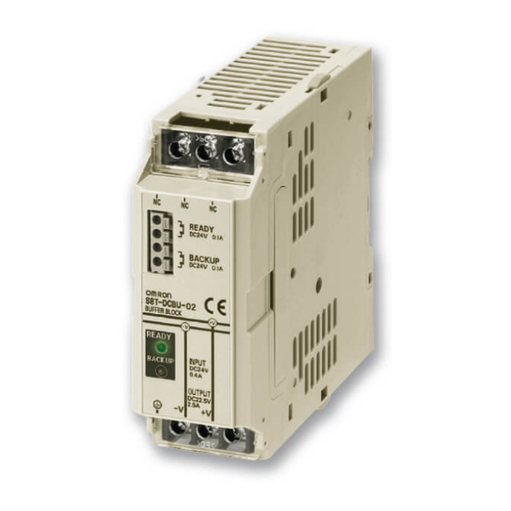
Buffer Block
S8T-DCBU-02
Prevents Equipment Stoppage, Data Loss,
and Other Problems Resulting from
Momentary Power Failures
• Provides a backup time of 500 ms at an output current of 2.5 A.
• Can be wired to the 24-V output from the S8VS, S82J, S82K,
and S8PS Power Supplies.
• Connects to an S8TS Power Supply via an S8T-BUS03 Bus
Line Connector.
• Parallel connections to up to four Blocks can be used to
increase the backup time and current capacities.
• Complies with SEMI F47-0200 standard.
Ordering Information
Buffer Block
Input voltage
24 VDC (24 to 28 VDC)
Options (Order Separately)
Bus Line Connector (Connects to Buffer Block)
Type
DC bus line
Note: One package contains 10 S8T-BUS03 Connectors.
Basic Configuration
Connection using Bus Line Connector
S8TS-06024@
(Order separately.)
S8T-BUS03
Bus Line Connector
(Order separately.)
S8T-DCBU-02
Output voltage
(during backup operation)
22.5 V
Number of Connectors
1 Connector
10 Connectors (See note.)
Connect to AC lines.
Load
Output current
2.5 A
S8T-BUS03
S8T-BUS13
Connection via Wiring
Connect to AC lines.
Load
Buffer Block
S8T-DCBU-02
S8TS
Model number
S8T-DCBU-02
Model number
S8T-DCBU-02
1
Advertisement
Table of Contents

Related Manuals for Omron S8T-DCBU-02


Summary of Contents for Omron S8T-DCBU-02
- Page 1 Buffer Block S8T-DCBU-02 Prevents Equipment Stoppage, Data Loss, and Other Problems Resulting from Momentary Power Failures • Provides a backup time of 500 ms at an output current of 2.5 A. • Can be wired to the 24-V output from the S8VS, S82J, S82K, and S8PS Power Supplies.
-
Page 2: Specifications
2. Refer to Backup Time on page 10 for details. 3. Refer to Functions on page 7 for details. 4. If the number of S8T-DCBU-02 Buffer Blocks to be connected is “N,” set the detection current to 20 mA × N. 5. Specified by S8TS-06024@ connection. -
Page 3: Block Diagram
Power Supply and the Buffer Block must be fully charged. If three or more S8T-DCBU-02 Buffer Block are used in parallel operation and the backup current exceeds 5 A, the momentary power failure time that can be compensated for will be reduced. -
Page 4: Selecting The Power Supply
Power Supply. Be sure to provide a sufficient cient. allowance rate. If the S8T-DCBU-02 is connected to a previously installed power sup- Calculation of the Total Power Supply Capacity ply, the voltage may drop due to the power supply's overcurrent pro- tection, or backup operations may not be possible. - Page 5 Using the Bus Line Connector the left or right end of the Blocks. Heat dissipation will be interfered with if the S8T-DCBU-02 Blocks are not connected to the end. When connecting to the S8TS-06024@, always use the S8T-BUS03 Bus Line Connector. This Connector connects only the DC lines. It...
-
Page 6: Mounting To Din Track
AC input. Use this procedure for maintenance as well. 1. Turn ON the AC power supply that has been connected. 2. Check the READY indicator on the S8T-DCBU-02 to confirm that it is lit. Indicator READY output relay... - Page 7 2. The backup operation will not be performed when the over- voltage circuit operates to shut OFF the output. The S8T-DCBU-02 will switch to the backup operation if a voltage drop is detected on the connected power supply. Reverse Connection Protection...
- Page 8 Nomenclature Buffer Block S8T-DCBU-02 A, B: READY Output: NC contact I: Protective Earth Terminal J: I/O Terminal ( − V) C, D: BACKUP Output: NC contact E: READY Indicator (READY: Green) K: I/O Terminal (+V) F: BACKUP Indicator (BACKUP: Red)
-
Page 9: Engineering Data
Momentary Power Failure or Voltage Drop AC input AC input Internal capacitor voltage Internal capacitor voltage I/O terminal voltage I/O terminal voltage Output current of the Output current of the S8T-DCBU-02 S8T-DCBU-02 open open READY output READY output closed closed READY indicator... -
Page 10: Backup Time
Note: 1. The backup time may be reduced if a fixed power load (such as a DC-DC converter) is connected. 2. If the input voltage increases, the output voltage for the backup operation will also increase, reducing the backup time due to the higher power consumption of the load. S8T-DCBU-02 Buffer Block... - Page 11 S8TS-06024@ 2 (+1) 98 W Block is connected. 170 W 5. The rated output current of the S8T-DCBU-02 is 2.5 A per 3 (+1) 152 W Block regardless of the number of S8TS-06024@ Blocks 230 W that are connected.
- Page 12 200 VAC 100 VAC 200 VAC S8TS 06024@ S82J 02524@@ S8VS 06024@ 05024@@ 09024@@ 10024@@ 2.95 12024@@ 15024@@ 18024@@ 30024@ 24024@@ 60024@ S82K 03024 0.25 S8PS 05024@@ 0.75 05024 10024@@ 09024/ 15024@@ 10024 P09024/ 30024@@ P10024 24024@ P24024@ S8T-DCBU-02 Buffer Block...
- Page 13 S82J 02524@@ 05024@@ 10024@@ 15024@@ 30024@ 60024@ S8PS 05024@@ 10024@@ 15024@@ 30024@@ Dimensions Note: All units are in millimeters unless otherwise indicated. Buffer Block Buffer Block S8T-DCBU-02 6 × M4 with square washer 80.7 (Sliding: 15 max.) S8T-DCBU-02 Buffer Block...
-
Page 14: End Plate
PFP-50N ± 0.15 ± 0.3 ± 0.15 15 (5)* 1,000 (500)* * Values in parentheses are for the PFP-50N. PFP-100N2 ±0.3 29.2 1,000 End Plate PFP-M M4 × 8 pan-head screw 35.5 35.3 11.5 M4 spring washer S8T-DCBU-02 Buffer Block... -
Page 15: Safety Precautions
Only power supplies with an output voltage of 24 V and an output capacity of 25 W or more can be connected. • Do not install the S8T-DCBU-02 in places subjected to shock or vibration. A device such as a contact breaker may be a vibration •... - Page 16 9.) • Use the S8T-DCBU-02 at a relative humidity of 25% to 85%. • Do not use the S8T-DCBU-02 where it would be subjected to direct sunlight. • Do not use the S8T-DCBU-02 where it would be subjected to penetration of liquid, foreign substance, or corrosive gas.
-
Page 17: Troubleshooting
Troubleshooting The following table lists the errors that may occur when the S8T-DCBU-02 is used, along with their probable causes and remedies. Check the rel- evant items. When Cause Description Remedies During installation The S8TS-06024@ and The Bus Line Connector is provided with a se-... - Page 18 S8T-DCBU-02 Blocks in parallel. Refer to Paral- lel Operation Connection on page 5. During actual The READY indicator is not The voltage input to the S8T-DCBU-02 may be Check the voltage at the I/O terminals of the operation lit and the READY output is 23 V or less.
- Page 19 S8T-DCBU-02 Buffer Block...
- Page 20 CONTRACT, WARRANTY, NEGLIGENCE, OR STRICT LIABILITY. In no event shall the responsibility of OMRON for any act exceed the individual price of the product on which liability is asserted. IN NO EVENT SHALL OMRON BE RESPONSIBLE FOR WARRANTY, REPAIR, OR OTHER CLAIMS REGARDING THE...
Need help?
Do you have a question about the S8T-DCBU-02 and is the answer not in the manual?
Questions and answers