Omron S8VK-X Series Manual
Switch mode power supply ethernet/ip, modbus tcp-compatible maximizing system availability through the connecting of equipment to iot
Hide thumbs
Also See for S8VK-X Series:
- Communications manual (58 pages) ,
- Instruction manual (2 pages)
Table of Contents
Advertisement
New Product
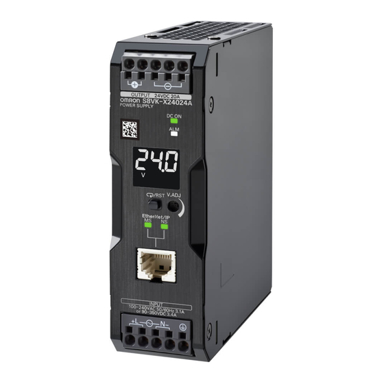
Switch Mode Power Supply
S8VK-X
EtherNet/IP, Modbus
TCP-Compatible
Maximizing System Availability
Through the Connecting of
Equipment to IoT
• Product replacement time, output voltage, output
current, and more are acquired on the network
and can be managed all at once
• Product status can be checked on-site using the
indication monitor
• Operation possible at ambient temperatures
from -40 to 70°C
• Power Boost function at 150% (240 and 480 W)
• Side-by-side mounting possible (up to 55°C)
• UL Class 2 conformance (90 W or less)
• Complies with EN/IEC 61558-2-16
• Coated PCBs for better resistance to environment
Refer to Safety Precautions on page 20.
Recommended Noise Filter
Noise filter
S8V-NF
Listed on page 28.
Model Number Structure
Model Number Legend
Note: Not all combinations are possible. Refer to List of Models in Ordering Information, below.
S8VK- X@@@@@@-EIP
1
2
3
1. Power Ratings
030: 30 W
060: 60 W
090: 90 W
120: 120 W
240: 240 W
480: 480 W
(60/120/240/480-W Models)
Output voltage
2.
05: 5 V
12: 12 V
24: 24 V
3. Indication monitor
A: With indication monitor
None: Without indication
monitor
1
Advertisement
Table of Contents


Need help?
Do you have a question about the S8VK-X Series and is the answer not in the manual?
Questions and answers