Table of Contents
Advertisement
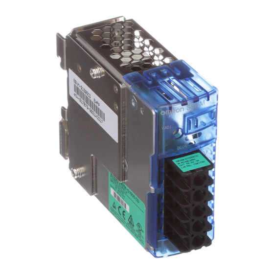
Switch Mode Power Supply
S8VM (15/30/50/100/150/300/600/1,500-W Models)
Power Supply Featuring OMRON's Unique, New Undervoltage Alarm Function with
Compact Body Contributing to Machine Downsizing
• New undervoltage alarm function assists in determining causes of errors (S8VM-@@@24A@/P@ only).
• Power failure alarm function provides notification of output voltage errors (300-, 600-, and 1,500-W models only).
• Broad range of possibilities with 8 capacities and 29 models to choose from.
• RoHS-compliant including lead-free construction.
• Safety standards: UL508/60950-1/1604, CSA C22.2 No. 14/No. 60950-1/No. 213, EN50178, EN60950-1 (The 300-, 600-, and
1,500-W models will not conform to safety standards if the customer replaces the fan.)
• Harmonic current emissions: Conforms to EN61000-3-2 (except for 15- and 30-W models).
• New, attentive design prevents screws from falling out of terminal block (except for output terminals of 300-, 600-, and 1,500-W
models).
• Finger protection prevents electric shock.
• DIN Rail mounting.
Note: Refer to Precautions for Safe Use on page 32.
Model Number Structure
Model Number Legend
Note: Not all combinations are possible. Please refer to the list of models in Ordering Information on page 2.
S8VM- @@@@@@@
3 4
1
2
1. Power Ratings
015:
15 W
030:
30 W
050:
50 W
100:
100 W
150:
150 W
300:
300 W
600:
600 W
152: 1,500 W
2. Output Voltage
05: 5 V
12: 12 V
15: 15 V
24: 24 V
Note: 1. The housing and terminal of the connector for the undervoltage alarm output are provided with the S8VM-05024A@/P@, S8VM-
10024A@/P@ and S8VM-15024A@/P@.
2. Bottom mounting models cannot be used for front mounting. For a front mounting configuration, use a DIN Rail mounting bracket model
or Mounting Brackets (sold separately).
3. A forced-air cooling method with a fan is used with 300-, 600-, and 1,500-W models.
3. Configuration/Functions
None: Open-frame type Standard type
C:
Covered type
Standard type
A:
Covered type
Undervoltage alarm type (Sinking)
(See note 1.)
P:
Covered type
Undervoltage alarm type (Sourcing)
(See note 1.)
4. Configuration
None:
Bottom mounting type (See note 2.)
D:
DIN Rail mounting bracket type
Switch Mode Power Supply
S8VM
1
Advertisement
Table of Contents

Related Manuals for Omron S8VM


Summary of Contents for Omron S8VM
- Page 1 Note: 1. The housing and terminal of the connector for the undervoltage alarm output are provided with the S8VM-05024A@/P@, S8VM- 10024A@/P@ and S8VM-15024A@/P@. 2. Bottom mounting models cannot be used for front mounting. For a front mounting configuration, use a DIN Rail mounting bracket model or Mounting Brackets (sold separately).
-
Page 2: Ordering Information
3. M8 bolts and nuts for the output terminals are not included with the S8VM-15224C. 4. The 300-, 600-, and 1,500-W models have fans. 5. To perform front mounting using the bottom mounting models, use the Mounting Brackets (S82Y-VM@@F, sold separately). S8VM... -
Page 3: Specifications
530 g max. Note: 1. Do not use the Inverter output for the Power Supply. Inverters with an output frequency of 50/60 Hz are available, but the rise in the internal temperature of the Power Supply may result in ignition or burning. - Page 4 3,800 g max. Note: 1. Do not use the Inverter output for the Power Supply. Inverters with an output frequency of 50/60 Hz are available, but the rise in the internal temperature of the Power Supply may result in ignition or burning.
-
Page 5: Block Diagrams
Photocoupler AC (L) Fuse Noise INPUT DC OUTPUT filter AC (N) Inrush Rectification Smooth- Rectifier/smoothing Harmonic current circuit current protection suppression circuit Drive control circuit Voltage Overcurrent detection circuit detection circuit Overvoltage detection circuit Photocoupler S8VM Switch Mode Power Supply... - Page 6 Output voltage monitor Overcurrent Control circuit detection circuit Remote sensing Rectifier/smoothing circuit Voltage detection circuit Over heat detection circuit Power supply Current balance Auxiliary power balance circuit supply circuit Overvoltage detection circuit Remote control Rectifier/smoothing Photocoupler circuit S8VM Switch Mode Power Supply...
- Page 7 Output voltage monitor Control circuit Remote sensing Rectifier/smoothing circuit Voltage detection circuit Over heat detection circuit Power supply Auxiliary power Current balance balance circuit supply circuit Overvoltage detection circuit Remote control Rectifier/smoothing circuit Photocoupler S8VM Switch Mode Power Supply...
- Page 8 Correct the voltage drop in the load lines. Short bars (See note 5.) Note: 1. The fuse is located on the (L) side. It is NOT user-replace- able. 2. If mounting is performed using a DIN Rail, the protective earthing connection is the panel mounting hole shown in the figure below.
-
Page 9: Engineering Data
If only 20 mm spacing is allowed, use the Power Supply at a load ratio of 80% or less. 4. When using 150-W models for a long period of time at an input voltage of 90 VAC or lower, reduce the load to 80% or less of the above derating curves. -
Page 10: Remote Sensing Function
4. When the +S and S terminals are opened with the short bar removed, the overvoltage protection function is activat- ed and the output voltage will be cut off. 5. If the load line is too long, use an electrolytic capacitor in the following 3 locations: 1) Across the load terminals... -
Page 11: Overload Protection
24.0 V). During detection, the transistor is OFF (with no continuity across 8 and 10) and the LED (6: Yellow) lights. (The Undervoltage Alarm Function 1 is used as a latch holding function.) •... - Page 12 Contact your OMRON representative if the Power Supply does not function normally after checking. The symbols in the table are as follows: : Lit, : Not lit, : Flashing Note: Flashing: The output voltage is unstable, causing the LED to repeatedly turn ON and OFF. DC ON DC LOW1 DC LOW2 Transistor...
- Page 13 The output voltage has returned to normal volt- Turn OFF the input power, and wait at least 60 s before turning ON the input power again to clear the age following a rapid drop caused by using the indicator status.
- Page 14 S8VM-300@@C (S8VM-300@@C/S8VM- 600@@C) FG terminal: Frame ground ter- minal (S8VM-15224C) DC output terminals ( V), ( V) Connect the load lines to these terminals. Output indicator (DC ON: Lights (green) while a direct current (DC) Green) output is ON. Output voltage adjuster Use to adjust the voltage.
- Page 15 Mounting lines. Connect the S pin (pin 2 on CN) to the positive load terminal and the S pin (pin 4 on CN) to the negative load terminal to enable remote sensing. When not using the remote sensing function, use Standard Mounting the standard connector.
-
Page 16: Remote Control Function
+RC pin (pin 7 on CN) and the -RC pin (pin 8 on CN). Connect a switch or transistor to the +RC and -RC pins to use the remote control function. When not using this... - Page 17 Outputs are interrupted if an overload continues for 5 seconds or more. To reset the Power Supply, leave input power OFF for more than 3 minutes and then turn it ON again. Alternatively, turn OFF and Output ON the remote control signal.
-
Page 18: Overheat Protection
The values shown in the above diagram are for reference only. Note: 1. Do not turn ON the input power again until the cause of the overvoltage has been removed. 2. The overvoltage protection function may be activated when the output voltage adjuster (V.ADJ) is set to a value that ex-... -
Page 19: Mounting Holes
Dimensions Note: All units are in millimeters unless otherwise indicated. Bottom Mounting Models (15-W, 30-W, 50-W, 100-W, 150-W Models) S8VM-015@@ 17.6 max. 80.5 S8VM-015@@C S8VM-01524A 81.5 68 0.5 8.5 0.5 Mounting Holes 62 0.5 Two, M3 (depth: 8 max.) 8.5 0.5... - Page 20 8.5 0.5 Mounting 23.5 0.3 15 0.2 68 0.5 Three, M3 (depth: 4 max.) 8 0.2 83 0.5 32.5 0.5 Note: The image is the S8VM-05024 Model. 13.6 max. 97 0.5 124.5 33.5 Bottom Three, 4 dia. Mounting 15 0.2 68 0.5...
- Page 21 26.5 0.2 Two, 4 dia. 15 0.2 Mounting 7.5 0.2 Three, M3 (depth: 4 max.) 120 0.5 25 0.5 Note: The image is the S8VM-15024 Model. 68 0.5 135 0.5 Bottom Three, 4 dia. Mounting 15 0.2 120 0.5 13.6 max.
- Page 22 S8VM-015@@D 17.6 max. 80.5 3.5 max. S8VM-015@@CD S8VM-01524AD 81.5 90.4 5.4 (Sliding: 9 max.) Note: The image is the S8VM-01524D Model. 15 max. 84.5 3.5 max. 35.1 84.5 46.2 94.4 5.4 (Sliding: 9 max.) Note: The image is the S8VM-01524AD Model.
- Page 23 17.6 max. 120.5 3.5 max. S8VM-050@@CD S8VM-05024AD S8VM-05024PD 82.5 130.4 5.4 (Sliding: 9 max.) Note: The image is the S8VM-05024D Model. 15 max. 124.5 3.5 max. 35.1 84.5 46.2 134.4 5.4 (Sliding: 9 max.) Note: The image is the S8VM-05024AD Model.
- Page 24 3.5 max. 39.1 160.5 S8VM-150@@CD S8VM-15024AD S8VM-15024PD 82.5 170.4 5.4 (Sliding: 9 max.) Note: The image is the S8VM-15024D Model. 15 max. 45.6 3.5 max. 164.5 84.5 46.2 174.4 5.4 (Sliding: 9 max.) Note: The image is the S8VM-15024AD Model.
- Page 25 M8 (See note.) 260 0.5 260 0.5 7.25 Horizontal Four, 4.5 dia. Mounting 112 0.5 60 0.5 260 0.5 Four, M4 (depth: 6 max.) Note: M8 bolts and nuts for the output terminals are not included. S8VM Switch Mode Power Supply...
-
Page 26: Mounting Brackets
Mounting Bracket A (bottom mounting for 15-, 30-, and 50-W models) S82Y-VM10B Mounting Bracket B (bottom mounting for 100- and 150-W models) S82Y-VM20B Mounting Bracket C (front mounting for 15-, 30-, 50-, 100-, and 150-W models) S82Y-VM10F Mounting Bracket D (bottom mounting for 300-W models) S82Y-VM30B... -
Page 27: Using The Mounting Bracket
Mounting Bracket C (Front Mounting for 15-, 30- 50-, 100-, and 150-W Models) S82Y-VM10F Using the Mounting Bracket 4 dia. 97 0.5 13.4 a, b Screws Used A: Accessories (Use the enclosed screws in two places for 15-W, 30-W and 50- W models and in three places for 100-W and 150-W models.) - Page 28 Mounting Bracket E (Horizontal Bottom Mounting for 300-W Models) S82Y-VM30S Using the Mounting Bracket Three, 4.5 dia. Screws Used A: Accessories (Use the enclosed screws in four places.) B: M4 (three places) Mounting screw tightening torque (recom- mended): 1.27 N·m...
- Page 29 Mounting Bracket G (DIN Rail Mounting for 300-W Models) S82Y-VM30D Using the Mounting Bracket 102.3 215.3 Screws Used A: Accessories 243 max. (Use the enclosed screws in four places.) Mounting screw tightening torque (recommended): 1.27 N·m Mounting Bracket H (Bottom Mounting for 600-W Models)
- Page 30 A: Accessories (Use the enclosed screws in four places.) B: M4 (three places) Mounting screw tightening torque (recommended): 1.27 N·m Mounting Bracket K (DIN Rail Mounting for 600-W Models) S82Y-VM60D Using the Mounting Bracket 102.3 222.3 257 max. Screws Used...
- Page 31 (for S8VM-05024A@/05024P@/10024A@/10024P@/15024A@/15024P@ Only) Using the Undervoltage Alarm Output Wiring Cable XHP-3 (Manufactured by JST) : AWG24 3,000 50 DIN Rail (Order Separately) Note: All units are in millimeters unless otherwise indicated. Mounting Rail (Material: Aluminum) PFP-100N PFP-50N 7.3 ± 0.15 35 ±...
-
Page 32: Safety Precautions
100@@@@/150@@@@) Keep the Power Supply as far away from heating elements as possible when installing. As a reference value, allow at least 50 mm spacing on the right and left sides. If only 20 Minor electric shock, fire, or Product failure may mm spacing is allowed, use the Power Supply at a load ratio of 80% occasionally occur. -
Page 33: Recommended Wire Sizes
40 A per terminal. The current rating for the output terminals on the be halved for each rise of 10 C or the life will be doubled for each S8VM-600@@C is 60 A per terminal. Use two terminals together if a drop of 10 C. -
Page 34: Insulation Test
If the S and S terminals are opened by removing the short bar, the overvoltage protection function will be activated and the output volt- If the CB pin (pin 5 on CN) and the CBG pin (pin 6 on CN) are con- age will be cut off. -
Page 35: Fan Replacement
The Power Supply will not conform to safety standards if the cus- tomer replaces the fan. Turn OFF the input power once and leave it OFF for at least 3 min- utes. Then turn it ON again to see if this clears the condition. -
Page 36: Warranty
CONTRACT, WARRANTY, NEGLIGENCE, OR STRICT LIABILITY. In no event shall the responsibility of OMRON for any act exceed the individual price of the product on which liability is asserted. IN NO EVENT SHALL OMRON BE RESPONSIBLE FOR WARRANTY, REPAIR, OR OTHER CLAIMS REGARDING THE...
Need help?
Do you have a question about the S8VM and is the answer not in the manual?
Questions and answers