Table of Contents
Advertisement
Quick Links
New Product
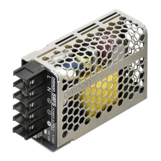
Switch Mode Power Supply (15/25/35/50/75/100/150/200/350-W Models)
S8FS-C
High Reliability at a Reasonable Cost.
Reliable, Basic Power Supplies That
Contribute to Stable Equipment
Operation.
• High Reliability: Enhanced abnormal overvoltage
resistance and lightning surge resistance for stable
operation even with an unstable input voltage.
• Long Life: Japanese 105°C electrolytic capacitors are used
to achieve stable quality and long life. A reliable 3-year
warranty.
*
• Wide Input Ranges: 100 to 120 VAC and 200 to 240 VAC
• Full Lineup: Models are available for the main output
voltages and capacities used in FA applications.
• Global Standards: Conforms to CE (all models), Approved
for UL (all models) and CCC (15 to 150-W models).
• Easy mounting to DIN Rails with Mounting Brackets.
* Refer to Period and Terms of Warranty on page 39.
Refer to Safety Precautions for All Power Supplies
and Safety Precautions on page 36.
Product Lineup
Output
voltage
15 W
5 V
Yes
12 V
Yes
15 V
Yes
24 V
Yes
36 V
---
48 V
---
Model Number Structure
Model Number Legend
Not all combinations are possible. Refer to List of Models in Ordering Information
Note:
S8FS-C
(1)
(2)
(3)
(1) Power Rating
Code
Power rating
015
15 W
025
25 W
035
35 W
050
50 W
075
75 W
100
100 W
150
150 W
200
200 W
350
350 W
25 W
35 W
50 W
Yes
Yes
Yes
Yes
Yes
Yes
Yes
Yes
Yes
Yes
Yes
Yes
---
---
---
---
---
Yes
(2) Output Voltage
Code
Output voltage
05
5 V
12
12 V
15
15 V
24
24 V
36
36 V
48
48 V
Power rating
75 W
100 W
Yes
Yes
Yes
Yes
Yes
Yes
Yes
Yes
---
Yes
Yes
Yes
.
on page 2
(3) Configuration
Code
Terminal Block Direction
Models with terminal block
Blank
facing upward
Models with terminal block
J
facing forward
D
Models with DIN rail
150 W
200 W
350 W
Yes
Yes
Yes
Yes
Yes
Yes
Yes
---
---
Yes
Yes
Yes
Yes
Yes
Yes
Yes
Yes
Yes
1
Advertisement
Table of Contents

Related Manuals for Omron S8FS-C Series


Summary of Contents for Omron S8FS-C Series
- Page 1 New Product Switch Mode Power Supply (15/25/35/50/75/100/150/200/350-W Models) S8FS-C High Reliability at a Reasonable Cost. Reliable, Basic Power Supplies That Contribute to Stable Equipment Operation. • High Reliability: Enhanced abnormal overvoltage resistance and lightning surge resistance for stable operation even with an unstable input voltage. •...
- Page 2 S8FS-C Ordering Information List of Models Note: For details on normal stock models, contact your nearest OMRON representative. Model with Model with Output voltage Model wtih Power rating Input voltage Output current Built-in fan terminal block terminal block (VDC) DIN rail...
- Page 3 S8FS-C Ratings, Characteristics, and Functions Power rating 15 W Item Output voltage 12 V 15 V 24 V 115 VAC input 80% typ. 84% typ. 84% typ. 85% typ. Efficiency * 230 VAC input 82% typ. 85% typ. 86% typ. 87% typ.
- Page 4 S8FS-C Power rating 25 W Output volt- Item 12 V 15 V 24 V 115 VAC input 80% typ. 84% typ. 85% typ. 86% typ. Efficiency * 230 VAC input 82% typ. 86% typ. 88% typ. 88% typ. Single phase 85 to 264 VAC, 120 to 370 VDC (The L terminal for the DC input is the positive side and safety Voltage range * standards do not apply.) (Derating is required according to the input voltage.
- Page 5 S8FS-C Power rating 35 W Item Output voltage 12 V 15 V 24 V 115 VAC input 81% typ. 83% typ. 84% typ. 87% typ. Efficiency * 230 VAC input 81% typ. 84% typ. 84% typ. 87% typ. Single phase 85 to 264 VAC, 120 to 370 VDC (The L terminal for the DC input is the positive side and safety Voltage range * standards do not apply.) (Derating is required according to the input voltage.
- Page 6 S8FS-C Power rating 50 W Item Output voltage 12 V 15 V 24 V 48 V 115 VAC input 79% typ. 83% typ. 84% typ. 86% typ. 87% typ. Efficiency * 230 VAC input 80% typ. 84% typ. 85% typ. 86% typ.
- Page 7 S8FS-C Power rating 75 W Item Output voltage 12 V 15 V 24 V 48 V 115 VAC input 75% typ. 83% typ. 84% typ. 87% typ. 87% typ. Efficiency * 230 VAC input 77% typ. 83% typ. 84% typ. 87% typ.
- Page 8 S8FS-C Power rating 100 W Item Output voltage 12 V 15 V 24 V 36 V 48 V 115 VAC input 80% typ. 82% typ. 83% typ. 85% typ. 86% typ. 87% typ. Efficiency * 230 VAC input 81% typ. 83% typ.
- Page 9 S8FS-C Power rating 150 W Item Output voltage 12 V 15 V 24 V 36 V 48 V 115 VAC input 81% typ. 84% typ. 85% typ. 86% typ. 86% typ. 87% typ. Efficiency * 230 VAC input 82% typ. 85% typ.
- Page 10 S8FS-C Power rating 200 W Item Output voltage 12 V 24 V 36 V 48 V 115 VAC input 81% typ. 85% typ. 88% typ. 89% typ. 88% typ. Efficiency * 230 VAC input 81% typ. 87% typ. 88% typ. 90% typ.
- Page 11 S8FS-C Power rating 350 W Item Output voltage 12 V 24 V 36 V 48 V 115 VAC input 77% typ. 83% typ. 86% typ. 87% typ. 87% typ. Efficiency * 230 VAC input 78% typ. 85% typ. 88% typ. 88% typ.
- Page 12 S8FS-C Conditions Efficiency The value is given for the rated output voltage and rated output current. Although some inverters give 50/60 Hz as the output frequency, do not use an inverter output as the power Voltage range source for the Power Supply. Doing so may result in smoking or burning due to internal temperature increases in the Power Supply.
- Page 13 S8FS-C Connections Block Diagrams S8FS-C015 (15 W) Fuse: 3.15 A AC (L) Noise Input DC output filter −V AC (N) Inrush current Rectifier Smoothing Rectifier/ protection circuit smoothing circuit Drive control circuit Overcurrent Voltage detection detection Photocoupler Overvoltage detection S8FS-C025 (25 W) S8FS-C035...
- Page 14 S8FS-C S8FS-C10005 (100 W) S8FS-C150 (150 W) Fuse: Rectifier/ smoothing circuit AC (L) Noise Input DC output filter −V AC (N) Inrush current Rectifier/ Input voltage selector switch protection smoothing circuit 100 to 120 VAC/ 200 to 240 VAC switching Drive control circuit Overcurrent...
- Page 15 S8FS-C S8FS-C35024 (350 W) Rectifier/ Fuse: smoothing circuit 10 A AC (L) Noise Input DC output filter −V AC (N) Inrush current Rectifier/ Input voltage selector switch protection smoothing circuit 100 to 120 VAC/ 200 to 240 VAC switching Drive control circuit Overcurrent Voltage...
- Page 16 S8FS-C Construction and Nomenclature Nomenclature 25-W, 35-W, 50-W, 15-W Models 100-W and 150-W Models 200-W and 350-W Models and 75-W Models S8FS-C025 S8FS-C050 S8FS-C100 S8FS-C200 S8FS-C350 S8FS-C035 S8FS-C075 S8FS-C150 S8FS-C015 S8FS-C025 S8FS-C200 S8FS-C050 S8FS-C100 S8FS-C350 S8FS-C035 S8FS-C075 S8FS-C150 Name Function Input terminals (L), (N) Connect the input lines to these terminals.
-
Page 17: Engineering Data
S8FS-C Engineering Data Derating Curves Derating for Ambient Temperatures Power rating 15 W 25 W 35 W 50 W 75 W 100 W 150 W 200 W 350 W Output voltage 12 V 15 V 24 V 36 V 48 V −30 −20 −10 −30 −20 −10 −30 −20 −10... - Page 18 S8FS-C Derating for Input Voltages Power rating 15 W 25 W 35 W 50 W 75 W 100 W 150 W 200 W 350 W Output voltage (11) (14) (11) (15) 12 V 15 V (9) (10) (11) (12) 24 V 36 V (13) (15) (11) (15)
- Page 19 S8FS-C Overload Protection The load and the Power Supply are automatically protected from short-circuit currents and overcurrent damage by this function. Overload protection is activated if the output current rises above 105% of the rated current. When the output current returns within the rated range, the overload protection is automatically cleared.
-
Page 20: Power Supplies
S8FS-C Dimensions (Unit: mm) Power Supplies Models with Terminal Block Facing Upward S8FS-C025 (25 W) 20.5 ±0.5 Panel mounting hole dimensions 8.16 Using the mounting Using the screw holes in the Power holes in the Supply Power Supply ±1 Bottom: Two, M3 (Depth: 5 mm max.) Two, M3 Two, 3.5 dia. - Page 21 S8FS-C S8FS-C075 (75 W) ±0.5 S8FS-C100 (100 W) Panel mounting hole dimensions 8.16 Using the mounting Using the screw holes in the Power holes in the Supply Power Supply Bottom: Two, M3 ±1 (Depth: 5 mm max.) Two, 3.5 dia. 84.5 Two, M3 ±0.5...
- Page 22 S8FS-C S8FS-C200 (200 W) Panel mounting hole dimensions 32.5 ±0.5 Using the screw holes in the Power Supply 8.16 Four, 4.5 dia. Bottom ±0.5 mounting 112.5 ±1 ±0.5 ±0.5 Four, 4.5 dia. Side mounting ±0.5 ±0.5 Nine, M3.5 Bottom: Four, M4 (Depth: 5 mm max.) ±1 32.5 ±0.5...
- Page 23 S8FS-C Models with Terminal Block Facing Forward S8FS-C015J (15 W) Panel mounting hole dimensions Using the screw holes in the Power Supply ±1 25.4 Two, 3.5 dia. Bottom Bottom: Two, M3 (Depth: 4 mm max.) mounting ±0.5 12.5 ±0.5 Two, 3.5 dia. Side 14 max.
- Page 24 S8FS-C S8FS-C050J (50 W) Bottom: Two, M3 (Depth: 5 mm max.) (12) Panel mounting hole dimensions Using the mounting Using the screw holes in the Power holes in the Supply Power Supply 85.5 ±0.5 ±0.5 ±1 Two, 3.5 dia. Two, M3 Bottom 85.5 ±0.5...
- Page 25 S8FS-C S8FS-C200J (200 W) Panel mounting hole dimensions 32.5 ±0.5 Using the screw holes in the Power Supply Four, 4.5 dia. Bottom ±0.5 mounting 112.5 ±1 ±0.5 ±0.5 Four, 4.5 dia. Side mounting ±0.5 ±0.5 Bottom: Four, M4 (Depth: 5 mm max.) (12) ±1 32.5...
- Page 26 S8FS-C Models with DIN rail S8FS-C015D (15 W) (12.15) 97.4 25.5 25.5 29.2 28.7 5 max. S8FS-C025D (25 W) (12.1) 117.5 32.5 75.5 49.5 36.2 35.2 5 max. 112.5 S8FS-C035D (35 W) (12.3) 117.5 49.5 85.5 47.5 37.2 35.2 5 max. 112.5...
- Page 27 S8FS-C S8FS-C050D (50 W) (12.1) 147.7 48.5 85.5 48.5 39.2 35.2 5 max. 112.5 S8FS-C075D (75 W) S8FS-C100D (100 W) 177.7 (12.1) 47.9 98.5 49.1 39.2 36.7 165.5 5 max. Note: The figure shows a 100-W Power Supply. A 75-W Power Supply has 5 terminals. S8FS-C150D (150 W) (12.1) 217.7...
- Page 28 S8FS-C S8FS-C200D (200 W) 230.7 (12) 56.25 94.75 56.25 51.2 49.2 5 max. 210.5 S8FS-C350D (350 W) 230.7 (12) 56.25 94.75 56.25 51.2 49.2 5 max. 210.5...
- Page 29 S8FS-C Mounting Brackets (Order Separately) Power rating Mounting direction Model 15 W S82Y-FSC015DIN 25 W S82Y-FSC025DIN 35 W S82Y-FSC050DIN 50 W 75 W DIN Rail 100 W S82Y-FSC150DIN 150 W 200 W S82Y-FSC350DIN 350 W 15 W S82Y-FSC015DIN-S 25 W S82Y-FSC025DIN-S 35 W S82Y-FSC035DIN-S...
- Page 30 S8FS-C S82Y-FSC050DIN Mounting Method (12) 147.7 (12) 117.7 3.5 dia. (35W) 48.5 49.5 85.5 ±1 48.5 3.5 dia. (50W) 47.5 Accessories (2 locations) Be sure to use the accessory screws. 4.5 (Sliding: 7.2 max.) Mounting screw tightening torque: 5.5 (Sliding: 8.2 max.) 0.48 to 0.59 N·m for M3 screws 39.2 37.2...
- Page 31 S8FS-C S82Y-FSC015DIN-S Mounting Method 38.7 Two, 3.5 dia. 25.5 ±1 25.5 4.5 (Sliding: 7.2 max.) Accessories (2 locations) Be sure to use the accessory screws. 43.2 ±1 Mounting screw tightening torque: 0.48 to 0.59 N·m for M3 screws 47.2 79.5 ±1 (13) 87.2...
- Page 32 S8FS-C S82Y-FSC050DIN-S Mounting Method 48.7 Two, 3.5 dia. 48.5 85.5 ±1 48.5 4.5 (Sliding: 7.2 max.) Accessories (2 locations) Be sure to use the accessory screws. Mounting screw tightening torque: 0.48 to 0.59 N·m for M3 screws 49.7 ±1 80.2 ±1 (12) 138.2...
- Page 33 S8FS-C S82Y-FSC350B (Four Brackets) Mounting Method (R2.2) 11.25 ±1 16.25 4.5 dia. 19.5 ±1 12.5 Accessories (4 locations) Be sure to use the accessory screws. 18.05 ±1 Mounting screw tightening torque: 1.08 Panel mounting hole dimensions to 1.32 N·m for M4 screws Note: The mounting bracket is available Four, M4...
- Page 34 *1. To mount an S8FS-series Power Supply that is not a DIN Rail-mounting model to a DIN Rail, purchase a DIN Rail-mounting Bracket separately from the Power Supply. *2. Consult with your OMRON representative if you use a 15-W or 35-W S8JC-Z Power Supply with a 48-V output voltage.
- Page 35 S8FS-C DIN Rail (Order Separately) Note: All units are in millimeters unless otherwise indicated. Mounting Rail (Material: Aluminum) ±0.15 Model ±0.3 ±0.15 PFP-100N 15 (5)* PFP-50N 1,000 (500)* * Value in parentheses are for PFP-50N. Mounting Rail (Material: Aluminum) Model 29.2 ±0.3 PFP-100N2...
-
Page 36: Safety Precautions
S8FS-C Safety Precautions Refer to Safety Precautions for All Power Supplies. Warning Indications Precautions for Safe Use Indicates a potentially hazardous situation CAUTION which, if not avoided, may result in minor Ambient Operating and Storage Environments or moderate injury or in property damage. •... - Page 37 S8FS-C Mounting Wiring • Connect the ground completely. The standard mounting pattern is shown below. A protective earthing terminal stipulated in safety standards is Mounting Pattern A used. Electric shock or malfunction may occur if the ground is not connected completely. •...
-
Page 38: Series Operation
S8FS-C Output Voltage Adjuster (V. ADJ) Parallel Operation • The output voltage adjuster (V. ADJ) may possibly be damaged if Parallel operation is not possible. it is turned with unnecessary force. Do not turn the adjuster with Parallel AC (L) Operation excessive force. -
Page 39: Warranty Period
* The maximum ratings must be within the derating curve. If the Power Supply fails for reasons attributable to OMRON within the above warranty period, OMRON will repair or replace the faulty part of the Power Supply at the place of purchase or the place where the Power Supply delivered without charge. - Page 40 MEMO...
-
Page 41: Terms And Conditions Agreement
Data presented in Omron Company websites, catalogs and other materials is provided as a guide for the user in determining suitability and does not constitute a warranty. It may represent the result of Omron’s test conditions, and the user must correlate it to actual application requirements. - Page 42 The Netherlands Hoffman Estates, IL 60169 U.S.A. Tel: (31)2356-81-300/Fax: (31)2356-81-388 Tel: (1) 847-843-7900/Fax: (1) 847-843-7787 © OMRON Corporation 2015-2016 All Rights Reserved. OMRON (CHINA) CO., LTD. OMRON ASIA PACIFIC PTE. LTD. In the interest of product improvement, Room 2211, Bank of China Tower, No.
Need help?
Do you have a question about the S8FS-C Series and is the answer not in the manual?
Questions and answers