Omron S8TS Product Manual
Switch mode power supply
Hide thumbs
Also See for S8TS:
- Manual (12 pages) ,
- Brochure & specs (6 pages) ,
- Instruction manual (1 page)
Table of Contents
Advertisement
Quick Links
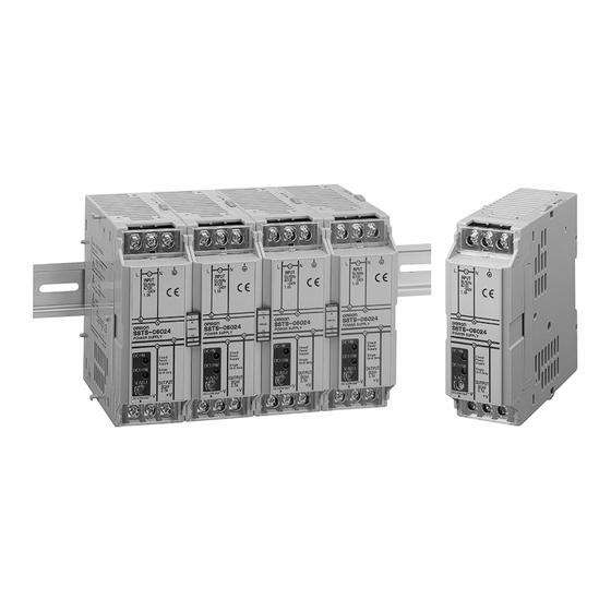
Switch Mode Power Supply
S8TS
Block-type Switch mode Power Supply That
Mounts to DIN Track
• Power supply range of 60 to 240 W available with just one model
(24-V models).
• Easy creation of multi-power supply configurations with different
output power supplies connected together (24-V, 12-V, and 5-V
models).
• Improve power supply system reliability by creating N+1 redun-
dant systems (24-V and 12-V models).
• Approved by UL/CSA standards, EN60950 (IEC 950), and VDE
0160.
Model Number Structure
■ Model Number Legend
S8TS-@@@@@@-@@
1
2
3
4
1. Capacity
2. Output Voltage
060: 60 W
24:
030: 30 W
12:
025: 25 W
05:
Ordering Information
■ Basic Block
Output voltage
24 V
2.5 A
12 V
2.5 A
5 V
5 A
■ Bus Line Connector
Type
AC line + DC line bus
(For parallel operation)
AC line bus
(For series operation or isolated operation)
Note 1. One S8T-BUS01 Connector and one S8T-BUS02 Connector are included as accessories.
2. Bus Line Connectors are ordered separately if necessary.
3. Attached connectors: 2ESDPLM-05P (for output terminal) and 3ESDPLM-03P (for input terminal) made by DINKLE ENTERPRISE.
4. One package contains 10 S8T-BUS01 Connectors.
5. One package contains 10 S8T-BUS02 Connectors.
3. Structure
24 V
None: Screw terminals
12 V
F:
Connector
5 V
terminals
Output current
With Bus Line
Connectors
(See note 1.)
S8TS-06024-E1
S8TS-03012-E1
---
1 Connector
10 Connectors (See note 4.)
1 Connector
10 Connectors (See note 5.)
4. Bus Line Connectors
None: Basic Block only
E1:
S8T-BUS01 and
S8T-BUS02
included
Screw terminal type
Without Bus Line
Connectors
(See note 2.)
S8TS-06024
S8TS-03012
S8TS-02505
Number of Connectors
Switch Mode Power Supply
Connector terminal type
(See note 3.)
With Bus Line
Without Bus Line
Connectors
Connectors
(See note 1.)
(See note 2.)
S8TS-06024F-E1
S8TS-06024F
S8TS-03012F-E1
S8TS-03012F
---
S8TS-02505F
Model number
S8T-BUS01
S8T-BUS11
S8T-BUS02
S8T-BUS12
S8TS
L-25
Advertisement
Table of Contents

Related Manuals for Omron S8TS


Summary of Contents for Omron S8TS
-
Page 1: Ordering Information
Note 1. One S8T-BUS01 Connector and one S8T-BUS02 Connector are included as accessories. 2. Bus Line Connectors are ordered separately if necessary. 3. Attached connectors: 2ESDPLM-05P (for output terminal) and 3ESDPLM-03P (for input terminal) made by DINKLE ENTERPRISE. 4. One package contains 10 S8T-BUS01 Connectors. -
Page 2: Specifications
(No. of Blocks) max. Note 1. Refer to page 31 for details on adjusting the output voltage for parallel operation. If set to less than 10%, the undervoltage detection func- tion may operate. Ensure that the output capacity and output current after adjustment do not exceed the rated output capacity and rated output current respectively. - Page 3 450 g max. Note 1. If set to less than 10%, the undervoltage detection function may operate. Ensure that the output capacity and output current after adjust- ment do not exceed the rated output capacity and rated output current respectively.
-
Page 4: Block Diagrams
DC LOW OUT Drive control circuit Undervoltage indicator/output Detection Overcurrent detection circuit circuit Overvoltage detection circuit Photocoupler Connected to Bus Connected to Bus Line Connector Line Connector S8TS L-28 Switch Mode Power Supply... - Page 5 F DC Output Terminal (+V): Connect load lines to this terminal. G Output Indicator (DC ON: Green): Lights while DC output is ON. H Undervoltage Indicator (DC LOW: Red): Lights when the voltage at the output terminal drops. I Output Voltage Adjuster (V.ADJ): Use to adjust the voltage.
-
Page 6: Operation
4 Blocks Yes, 5 Blocks S8TS-02505@ N+1 Redundant Systems To ensure stable operation when there is a failure in one of the Blocks, use within the derating curve for N+1 redundant systems. Multi-output Power Supply Wiring Linked Blocks Up to 4 Basic Blocks with different output voltage specifications can be linked. -
Page 7: Inrush Current
200 VAC. When N Blocks are linked together, the inrush cur- rent will be equal to N times that for 1 Basic Block. Be sure to use a fuse with the appropriate fusing characteristics or a breaker with the appropriate tripping characteristics. -
Page 8: Engineering Data
Ambient temperature (˚C) Ambient temperature (˚C) Note: If there is a derating problem, use forced air-cooling. The ambient temperature is specified for a point 50 mm below the power supply. ■ Overload Protection ■ Overvoltage Protection The Power Supply is provided with an overload protection function... - Page 9 ■ Inrush Current, Startup Time, ■ Undervoltage Indicator and Hold Time Undervoltage Detection Output When a drop in the output voltage is detected, the red indicator (DC Input ON Input OFF LOW) lights and transistor (DC LOW: OUT) output turns ON. The...
- Page 10 Dimensions Note: All units are in millimeters unless otherwise indicted. S8TS-@@@@@ LOCK INPUT 50/60Hz AC100 -240V 1.0A S8TS-06024 80.7 POWER SUPPLY DC ON Class2 Power Supply DC LOW OUTPUT V.ADJ DC24V 2.5A DC LOW (Sliding: 15 max.) M4 with square washer...
-
Page 11: End Plate
End Plate PFP-M M4 8 pan-head screw 35.5 35.5 11.5 M4 spring washer S8TS L-35 Switch Mode Power Supply... -
Page 12: Installation Environment
Be sure to wire I/O terminals correctly. When tightening the termi- Block while the power is being supplied. Doing so may result in nals, do not exert a force of 100 N or more on terminal blocks or con- electric shock. -
Page 13: Charging Batteries
DIN Track Mounting Do not use or store the Power Supply in the following locations. To mount the Block on a DIN track, hook portion (A) of the Block onto Doing so may result in failure, malfunction, or deterioration of perfor- the track and press the Block in direction (B). - Page 14 ALL DIMENSIONS SHOWN ARE IN MILLIMETERS. To convert millimeters into inches, multiply by 0.03937. To convert grams into ounces, multiply by 0.03527. In the interest of product improvement, specifications are subject to change without notice. Cat. No. T022-E1-03 S8TS L-38...
Need help?
Do you have a question about the S8TS and is the answer not in the manual?
Questions and answers