Table of Contents
Advertisement
Available languages
Available languages
Nuovo prodotto
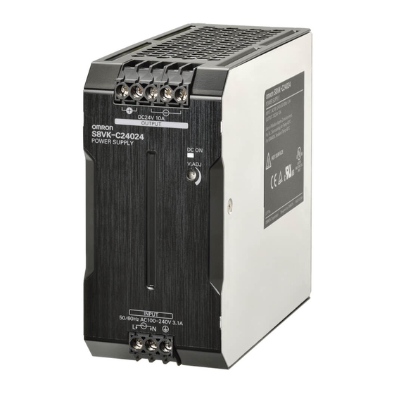
Alimentatore switching
S8VK-C
Alimentatore monofase dal prezzo
conveniente. Ingresso universale e standard
di sicurezza per tutte le applicazioni.
Design compatto per un ingombro minimo
• Ingresso universale per tutte le applicazioni:
100... 240 Vc.a. (85... 264 Vc.a.)
• Ingresso: 90... 350 Vc.c.
• Campo di temperature di esercizio: –25... 60°C
• Design compatto per l'utilizzo in spazi ridotti
• Installazione flessibile tramite le speciali staffe di montaggio
• Norme di sicurezza:
UL508/60950-1, CSA C22.2 N. 107.1/60950-1
EN50178 (=VDE0160), EN60950-1 (=VDE0805)
• EMS: in conformità a EN61204-3
EMI: EN55011 classe A
Fare riferimento alle Precauzioni per la sicurezza per tutti gli
!
alimentatori e alle Precauzioni per la sicurezza a pagina 11.
Modelli disponibili
Legenda codice modello
Nota: non tutte le combinazioni sono possibili. Vedere l'elenco dei modelli nella sezione Informazioni per l'ordine seguente.
S8VK-C @@@ 24
1
2
1. Potenza
060: 60 W
120: 120 W
240: 240 W
480: 480 W
Informazioni per l'ordine
Nota: Per informazioni dettagliate sui modelli standard, rivolgersi all'ufficio OMRON di zona.
Potenza
Tensione di ingresso
60 W
Monofase
120 W
100... 240 Vc.a.
240 W
90... 350 Vc.c.
480 W
(modelli da 60/120/240/480 W)
2. Tensione di uscita
24: 24 V
Tensione di uscita
24 V
24 V
24 V
24 V
Corrente in uscita
Modello
2,5 A
S8VK-C06024
5 A
S8VK-C12024
10 A
S8VK-C24024
20 A
S8VK-C48024
1
Advertisement
Table of Contents

Related Manuals for Omron S8VK-C


Summary of Contents for Omron S8VK-C
- Page 1 060: 60 W 24: 24 V 120: 120 W 240: 240 W 480: 480 W Informazioni per l’ordine Nota: Per informazioni dettagliate sui modelli standard, rivolgersi all’ufficio OMRON di zona. Potenza Tensione di ingresso Tensione di uscita Corrente in uscita Modello...
- Page 2 S8VK-C Caratteristiche Valori nominali, caratteristiche e funzioni Potenza 60 W 120 W 240 W 480 W Caratteristiche Tensione di uscita 24 V 24 V 24 V 24 V Efficienza (tipica) Ingresso 230 Vc.a. Tensione*1 100… 240 Vc.a., 90… 350 Vc.c. (campo consentito: 85… 264 Vc.a.)*6 Frequenza*1 50/60 Hz (47…...
-
Page 3: Diagrammi A Blocchi
S8VK-C Collegamenti Diagrammi a blocchi S8VK-C06024 (60 W) Fusibile: 250 Vc.a. 6,3 A HBC c.a. (L) Filtro USCITA c.c. INGRESSO −V antidisturbo c.a. (N) −V Protezione Raddrizzatore/ Livellatore Raddrizzatore dalla corrente Livellatore di spunto −V Circuito di controllo Circuito di rileva-... -
Page 4: Descrizione Del Pannello Frontale
S8VK-C Descrizione del pannello frontale Modelli da 60 W Modelli da 120 W Modelli da 240 W Modelli da 480 W S8VK-C06024 S8VK-C12024 S8VK-C24024 S8VK-C48024 Tipo Funzione Terminali di ingresso (L), (N) Collegare le linee di ingresso a questi terminali*1... -
Page 5: Protezione Da Sovraccarico
S8VK-C Montaggio Protezione da sovratensioni Tenendo conto dell’eventualità di sovratensioni, è opportuno (B) Montaggio con parte (A) Montaggio standard realizzare il sistema in modo tale che il carico non sia soggetto a una frontale verso l’alto (verticale) tensione eccessiva anche in caso di guasto del circuito di feedback dell’alimentatore. - Page 6 Applicazione dei modelli monofase su due fasi Per tutti i modelli monofase, S8VK-C In generale l’alimentatore monofase OMRON può essere utilizzato su due fasi di un sistema trifase nelle seguenti condizioni. 1. La tensione di alimentazione è inferiore all’ingresso nominale massimo.
- Page 7 S8VK-C Dimensioni (unità: mm) S8VK-C06024 (60 W) Ø 3,6 (Bit n. 1) 75,4 34,9 Ø 3,6 (Bit n. 1) Fermo guida 7,62 (Scorrimento: 10 max.) S8VK-C12024 (120 W) 122,2 117,8 112,2 6,35 Ø 5,0 (Bit n. 2) 104,6 34,7 Ø 5,0 (Bit n. 2)
- Page 8 S8VK-C Guida DIN (da ordinare separatamente) Nota: salvo diversa indicazione tutte le misure sono in millimetri. (materiale: alluminio) PFP-100N PFP-50N ±0,15 ±0,3 ±0,15 15 (5)* 1.000 (500)* * I valori tra parentesi si riferiscono al modello PFP-50N. (materiale: alluminio) PFP-100N2 29,2 ±0,3...
- Page 9 S8VK-C Staffe di montaggio Tipo Modello Staffa di montaggio frontale (per i modelli da 60 W) S82Y-VS10F Staffa di montaggio frontale (per i modelli da 120, 240 e 480 W) S82Y-VK10F Staffa di montaggio laterale (per i modelli da 60 W)
- Page 10 S8VK-C Tipo Modello Dimensioni Aspetto Montaggio Montaggio Ø 4,5 ±0,1 sul lato sinistro sul lato destro Staffa di montaggio ±0,1 laterale S82Y-VS10S (per i modelli da 60 W) ±0,1 s = 2,0 Montaggio Montaggio sul lato sinistro sul lato destro 15,5 ±0,1...
-
Page 11: Precauzioni Per La Sicurezza
S8VK-C Precauzioni per la sicurezza Avvertenza Indica una situazione di potenziale pericolo che, se non evitata, può essere causa di lesioni non gravi a persone o danni alla proprietà. ATTENZIONE Modalità d’uso Commenti supplementari sulle per garantire operazioni da eseguire o da evitare per la sicurezza utilizzare il prodotto in modo sicuro. -
Page 12: Ambiente Di Installazione
• Prima di accendere il prodotto, occorre rimuovere tutte le protezioni applicate per la lavorazione sulla macchina per evitare che ostacolino la dissipazione del calore. • Per il collegamento all’alimentatore S8VK-C utilizzare i cavi elencati di seguito in modo da evitare fumo o scintille dovuti a carichi anomali. -
Page 13: Utilizzo Corretto
S8VK-C Utilizzo corretto Montaggio Montaggio su guida DIN • Adottare misure appropriate per garantire un’adeguata Per montare l’alimentatore su una guida DIN, appoggiare il lato dissipazione del calore al fine di estendere l’affidabilità del superiore del sistema di aggancio (A) dell’alimentatore sulla guida prodotto. - Page 14 In caso di assenza della tensione di uscita, prima di contattare Omron eseguire i controlli indicati di seguito: • Controllo dello stato di protezione da sovraccarico: Controllare se il carico è in stato di sovraccarico o cortocircuito.
-
Page 15: Garanzia
Garanzia e limitazioni di responsabilità GARANZIA OMRON garantisce i propri prodotti da difetti di fabbricazione e di manodopera per un periodo di un anno (o per altro periodo specificato) dalla data di vendita da parte di OMRON. OMRON NON RICONOSCE ALTRA GARANZIA, ESPRESSA O IMPLICITA, COMPRESE, IN VIA ESEMPLIFICATIVA, LA GARANZIA DI COMMERCIABILITÀ, DI IDONEITÀ... - Page 16 In una prospettiva di miglioramento del prodotto, le informazioni contenute Cat. No. T058-IT2-01 nel presente documento sono soggette a modifiche senza preavviso. ITALIA SVIZZERA Omron Electronics SpA Nord Ovest Tel: +39 02 326 88 00 Omron Electronics AG Viale Certosa, 49 - 20149 Milano Milano...
-
Page 17: Switch Mode Power Supply
120: 120 W 24: 24 V 240: 240 W 480: 480 W 960: 960 W Ordering Information Note: For details on normal stock models, contact your nearest OMRON representative. Power ratings Input voltage Output Voltage Output current Boost Current Model number... - Page 18 S8VK-T Specifications Ratings, Characteristics, and Functions Power rating 120 W 240 W Item Output voltage 24 V 24 V Efficiency 3-phase, 400 VAC input *11 89% typ. 89% typ. 3-phase, 380 to 480 VAC (allowable range: 320 to 576 VAC) Voltage range *1 2-phase, 380 to 480 VAC (allowable range: 340 to 576 VAC) 450 to 600 VDC (allowable range: 450 to 810 VDC) *8...
- Page 19 S8VK-T Power rating 480 W 960 W (768 W *18) Item Output voltage 24 V 24 V Efficiency 3-phase, 400 VAC input *11 91% typ. 92% typ. 3-phase, 380 to 480 VAC (allowable range: 320 to 576 VAC) 3-phase, 380 to 480 VAC 2-phase, 380 to 480 VAC (allowable range: 320 to 576 VAC) Voltage range *1...
- Page 20 S8VK-T *1. Do not use an inverter output for the Power Supply. Inverters with an output frequency of 50/60 Hz are available, but the rise in the internal temperature of the Power Supply may result in ignition or burning. *2. For a cold start at 25C. Refer to Engineering Data on page 7 to 8 for details. *3.
- Page 21 S8VK-T Connections Block Diagrams S8VK-T12024 (120 W) S8VK-T24024 (240 W) INPUT Noise filter DC OUTPUT −V Rectifier lnrush Smoothing Rectifier/ current circuit smoothing protection circuit Drive control circuit Voltage detection circuit Overcurrent Overvoltage detection circuit detection circuit Photocoupler S8VK-T48024 (480 W) S8VK-T96024 (960 W) INPUT Noise filter...
- Page 22 S8VK-T Construction and Nomenclature Nomenclature 120 W Model 240 W Model 480 W Model S8VK-T12024 S8VK-T24024 S8VK-T48024 960 W Model S8VK-T96024 Note: A: The output current can use 100% of the rated output current. B: Overcurrent protection limits the output current to 80% of the rated output current.
-
Page 23: Engineering Data
S8VK-T Engineering Data Derating Curve 120 W (S8VK-T12024) 960 W (S8VK-T96024): Standard mounting −40 −25 −10 0 10 20 30 40 50 60 70 80 −40 −25 −10 0 10 20 30 40 50 60 70 80 Ambient temperature (°C) Ambient temperature (°C) Note: This is the guaranteed value for startup. -
Page 24: Overvoltage Protection
S8VK-T Mounting Overvoltage Protection Consider the possibility of an overvoltage and design the system so (B) Face-up mounting (A) Standard (Vertical) mounting that the load will not be subjected to an excessive voltage even if the feedback circuit in the Power Supply fails. If an excessive voltage that is approximately 130% of the rated voltage or more is output, the output voltage is shut OFF. - Page 25 S8VK-T Dimensions (Unit: mm) S8VK-T12024 (120 W) 122.2 ±1 117.8 ±1 6.35 112.2 104.6 ±1 6.35 (10) 19.8 Rail Stopper (Sliding: 7.5 max.) S8VK-T24024 (240 W) ±1 145.6 ±1 6.35 104.6 ±1 6.35 (10) 19.8 Rail Stopper (Sliding: 7.5 max.) S8VK-T48024 (480 W) ±1 145.6...
-
Page 26: End Plate
S8VK-T DIN Rail (Order Separately) Note: All units are in millimeters unless otherwise indicated. Mounting Rail (Material: Aluminum) PFP-100N PFP-50N 7.3 ± 0.15 35 ± 27 ± 0.15 15(5) * 1,000 (500) * * Values in parentheses are for the PFP-50N. Mounting Rail (Material: Aluminum) PFP-100N2 35 ±... -
Page 27: Mounting Brackets
S8VK-T Mounting Brackets Name Model Qty used Front-mounting bracket (for 120, 240 and 480 W models) S82Y-VK10F Front-mounting bracket (for 960 W model) S82Y-VK10F Side-mounting bracket (for 120 W model) S82Y-VK10S Side-mounting bracket (for 240 W model) S82Y-VK20S Note: Be sure to use the accessory screws. Mounting screw tightening torque (recommended): 4.43 to 5.31 lb-in (0.5 to 0.6 N·m) Type Model... -
Page 28: Safety Precautions
S8VK-T Safety Precautions Warning Indications Indicates a potentially hazardous situation which, if not avoided, may CAUTION result in minor or moderate injury or in property damage. Supplementary comments on what to Precautions for do or avoid doing, to use the product Safe Use safely. - Page 29 S8VK-T Precautions for Safe Use Wiring Connect the ground completely. A protective earthing terminal Use the following material for the wires to be connected to the stipulated in safety standards is used. Electric shock or malfunction S8VK-T to prevent smoking or ignition caused by abnormal loads may occur if the ground is not connected completely.
- Page 30 S8VK-T Mounting Power Boost Function Take adequate measures to ensure proper heat dissipation to For All Models increase the long-term reliability of the Product. Be sure to allow Power Boost is a function that can output the temporary repeated convection in the atmosphere around devices when mounting.
-
Page 31: Parallel Operation
S8VK-T Making Positive/Negative Outputs Parallel Operation The outputs are floating outputs (i.e., the primary circuits and Parallel operation is used when the output current from one Power secondary circuits are separated). You can therefore make Supply is insufficient for the load. Power Supplies are connected in positive and negative outputs by using two Power Supplies. -
Page 32: Backup Operation
S8VK-T Backup Operation In Case There Is No Output Voltage Backup operation is possible if you use two Power Supplies of the The possible cause for no output voltage may be that the overcurrent same model. or overvoltage protection has operated. The internal protection may Even if one Power Supplies fails, operation can be continued with the operate if a large amount of surge voltage such as a lightening surge other Power Supply. - Page 33 S8VK-T Recommended Replacement Periods and Periodic Replacement for Preventive Maintenance The recommended replacement period for preventive maintenance is greatly influenced by the application environment of the product. As a guideline, the recommended replacement period is 7 to 10 years.* To prevent failures or accidents that can be caused by using a product beyond its service live, we recommend that you replace the product as early as possible within the recommended replacement period.
-
Page 34: Terms And Conditions Agreement
Data presented in Omron Company websites, catalogs and other materials is provided as a guide for the user in determining suitability and does not constitute a warranty. It may represent the result of Omron’s test conditions, and the user must correlate it to actual application requirements. - Page 35 Hoffman Estates, IL 60169 U.S.A. The Netherlands Tel: (1) 847-843-7900/Fax: (1) 847-843-7787 Tel: (31)2356-81-300/Fax: (31)2356-81-388 © OMRON Corporation 2014-2016 All Rights Reserved. OMRON (CHINA) CO., LTD. OMRON ASIA PACIFIC PTE. LTD. In the interest of product improvement, Room 2211, Bank of China Tower, No.
Need help?
Do you have a question about the S8VK-C and is the answer not in the manual?
Questions and answers