Table of Contents
Advertisement
Advertisement
Table of Contents

Subscribe to Our Youtube Channel
Related Manuals for Omron S8AS


Summary of Contents for Omron S8AS
- Page 1 Smart Power Supply S8AS USER'S MANUAL Cat. No. Z269-E1-05...
- Page 3 S8AS Smart Power Supply User’s Manual Revised September 2013...
-
Page 5: About This Manual
Please read this manual carefully and be sure you understand the information provided before attempting to install or operate the S8AS Smart Power Supply. Be sure to read the precautions pro- vided in the following section. -
Page 7: Table Of Contents
S8AS Operating Procedure ........ - Page 8 TABLE OF CONTENTS SECTION 6 Communications ........CompoWay/F Communications Specifications .
-
Page 9: Terms And Conditions Agreement
Terms and Conditions Agreement Read and understand this Manual Please read and understand this catalog before purchasing the products. Please consult your OMRON representative if you have any questions or comments. Warranty, Limitations of Liability Warranties ● Exclusive Warranty Omron’s exclusive warranty is that the Products will be free from defects in materials and workmanship for a period of twelve months from the date of sale by Omron (or such other period expressed in writing by Omron). - Page 10 Data presented in Omron Company websites, catalogs and other materials is provided as a guide for the user in determining suitability and does not consti- tute a warranty. It may represent the result of Omron’s test conditions, and the user must correlate it to actual application requirements. Actual performance is subject to the Omron’s Warranty and Limitations of Liability.
-
Page 11: Safety Precautions
Safety Precautions ■ Precaution Classifications The following conventions are used to indicate and classify precautions in this manual. Always heed the information provided with them. Failure to heed precautions can result in injury to people or damage to property. Indicates a potentially hazardous situation which, if not CAUTION avoided, may result in minor or moderate injury or in property damage. -
Page 12: Precautions For Safe Use
17. Although some inverters have an output frequency of 50/60 Hz, they may cause internal temperatures to rise, possibly resulting in burning, if they are connected as the power source for the S8AS. Do not use the output from an inverter as the power source for the S8AS. - Page 13 ■ Installation and Wiring Minor electric shock during operation may occasionally occur. Always attach the cover or take other precautions so that the terminals cannot be touched directly. Also, connect the ground completely. The ground is a protective earth (PE) terminal specified in safety standards.
-
Page 14: Precautions For Correct Use
The long-term reliability of the S8AS can be increased by installing it properly and sufficiently considering heat dissipation. Be sure to install the S8AS so that the air flow circulates around it, because the S8AS is designed to radiate heat by means of natural air circulation. - Page 15 ■ Abnormal Current Tripping The S8AS has an abnormal current tripping function. A branch output will be cut off if its current exceeds a pre- set value. Also, all branch outputs will be cut off if their total peak output current exceeds a specified value.
-
Page 16: Startup Delay
20 mA. Note 1. The S8AS may possibly be damaged from the impulse voltage if a testing device switch is used to abruptly apply or cut off 3000 VAC. Increase the applied voltage gradually using the voltage adjustment on the testing device. - Page 17 To accurately confirm the output voltage, measure it at the branch output terminal. ■ Prohibition of Parallel Connection Do not connect branch outputs from the S8AS in parallel. Also, do not connect the branch outputs in parallel with branch outputs of other S8AS Power Supplies. S8AS...
-
Page 18: Using This Manual
Using this Manual ■ Notation in this Manual In this manual, the S8AS Smart Power Supply is referred to as the S8AS. ■ Notation of Setting Data Setting data codes and contents are displayed in seven-segment display characters, as shown in the following diagram. -
Page 19: Features And Functions
S8AS Operating Procedure ........ -
Page 20: Overview Of Features And Functions
Mode Power Supply and the S8M Digital Multicircuit Protector in one unit. The input power supply to the S8AS is 100 to 240 VAC at 50/60 Hz. Models are available for 240 W with 6 branch outputs or for 480 W with 8 branch out- puts, with and without communications. - Page 21 RS-485 communications. Branch Output Tripping Circuits No-contact Switching The S8AS built-in circuit protectors differ from conventional mechanical con- tact-type circuit protectors in that they use no-contact transistor relay switch- ing. Without the contact life of mechanical circuit protectors, semiconductor relays are able to provide a much longer lifetime.
- Page 22 • The external output terminal for tripping alarms (TRP) will turn ON. (The photoswitch output will turn OFF.) Internal Temperature The S8AS has an built-in temperature sensor that constantly measures the Monitor internal temperature. The temperature can be read from the seven-segment display.
- Page 23 (TRP) will not operate. The overcurrent protection fuse or over-temperature fuse cannot be replaced. If a fuse burns out, use a different branch output or replace the S8AS. External Outputs The S8AS has 4 external outputs: the Tripping Alarm Output (TRP), Under- voltage Detection Output (LOW), Maintenance Forecast Monitor Output (LFE), and Over-temperature Output (TMP).
- Page 24 The default setting is protection level 1. (For details, refer to 4-3 Changing the Protection Level.) Note The read/write access for models that do not support parameter changes (S8AS-24006N/48008N) cannot be changed regardless of the protection level.
-
Page 25: S8As Operating Modes
S8AS Operating Modes Section 1-2 S8AS Operating Modes The S8AS has 3 operating modes: Run Mode, Setting Mode, and Test Mode. Run Mode The output voltage, output current, internal temperature, and run time are monitored while supplying 24 VDC to the branch outputs. - Page 26 If the S8AS has been turned ON already, it will enter Run Mode or Test Mode Procedure the next time that power is turned ON. If the S8AS was in Test Mode when the power went OFF, it will start in Test Mode. If it was in a mode other than Test Mode when the power went OFF, it will start in Run Mode.
-
Page 27: Table Of Basic Functions
Test Mode to Run Mode, it will not be connected (ON) in Run Mode. (3) If the power is turned OFF while the S8AS is in Test Mode, the S8AS will start in Test Mode the next time that the power is turned ON, but all branch outputs will be OFF. - Page 28 Undervoltage The undervoltage detection output (LOW) is output 18.0 to detection thresh- when the output voltage of the S8AS falls below this 26.4 V detection threshold. The detection threshold can be set in 0.1-V increments. Branch outputs will not be cut off.
- Page 29 (See note Note (1) The tripping function operates within 100 ms when the S8AS is set to standard detection, within 20 ms when it is set to instantaneous detec- tion, and within 1,000 ms when it is set to extended detection.
- Page 30 Table of Basic Functions Section 1-3 Alarm Output and Error Display Functions Symbol Output Operation Error code name displayed Tripping Abnormal Voltage Tripping Operation alarm output When the output voltage exceeds 28.8 VDC, all branch outputs are cut off and the TRP output is turned ON.
-
Page 31: S8As Operating Procedure
S8AS Operating Procedure Section 1-4 S8AS Operating Procedure Using the S8AS Typical Startup Procedure Using the S8AS's Keys Preparation See Section 3 Installation and Wiring. Installation and wiring Power ON Set parameters See Section 4 Initial Settings. (S8AS-24006N/48008N parameters cannot be changed.) See Section 5 Trial Run. - Page 32 S8AS Operating Procedure Section 1-4 Desired objective/ Settings Details usage Monitor temperature In Setting Mode, set the over-temperature output p. 35, rise in control panel threshold (TMP). Take the signal from the Over- p. 65 and prevent over- temperature Output (TMP) terminal and use that p.
-
Page 33: Specifications And Functions
Specifications and Functions This section provides the specifications of the S8AS and describes special S8AS functions. Component Names and Functions ....... . . -
Page 34: Component Names And Functions
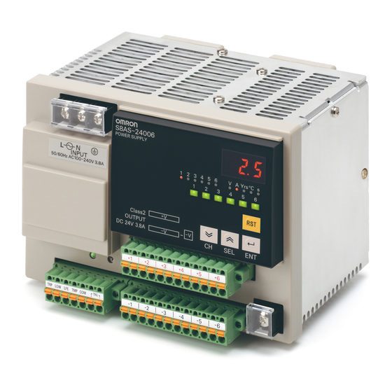
Component Names and Functions Section 2-1 Component Names and Functions Component Names ■ 240-W Output Models 1. AC input terminals 13. Communications terminals 2. Protective earth (PE) terminal 9. Branch output indicators 8. Seven-segment display 10. Unit indicators 11. Status indicators 12. -
Page 35: Component Names And Functions
(The photoswitch output will turn OFF.). Undervoltage Detec- Turns ON when the 24-VDC output voltage tion Output from the S8AS falls below the threshold. (The photoswitch output will turn OFF.). Maintenance Forecast Turns ON to indicate when the number of years... - Page 36 (6) Output Indicator (DC ON) The indicator is lit green when the S8AS is in normal operation. It indicates that the 24 VDC output can be used as a supply voltage. DC ON (7) Output Voltage Adjuster (V.ADJ)
- Page 37 Component Names and Functions Section 2-1 °C Lit when displaying the temperature. Lit when setting the startup sequence time or shutdown sequence time. (11) Status indicators (Green/Red) Indicate the connection and cut off status for the branch outputs. • Six-branch Output Model Not lit Set to OFF (disconnected) or forcibly connected...
-
Page 38: Internal Configuration
Internal Configuration Section 2-2 Internal Configuration S8AS-24006 (Model with NO Communications and Changeable Parameter Settings) S8AS-24006N (Model with NO Communications and Unchangeable Parameter Settings) S8AS-24006R (Model with Communications and Changeable Parameter Settings) (S8AS-24006R only) RS-485 A (−) Communica- tions B (+) - Page 39 OFF. • When an internal circuit has failed, the components can generate exces- sive heat. As a safety precaution against this kind of failure, the S8AS is equipped with a function that cuts off operation using a thermal fuse.
-
Page 40: Specifications
Specifications Section 2-3 Specifications Ratings and Characteristics S8AS-24006@ Item Model S8AS-24006 S8AS-24006N S8AS-24006R Efficiency (Typ.) 80% min. Input Voltage range (See note 1.) 100 to 240 VAC (85 to 264 VAC) condi- Frequency (See note 1.) 50/60 Hz (47 to 63 Hz) - Page 41 Specifications Section 2-3 Item Model S8AS-24006 S8AS-24006N S8AS-24006R Func- Over-temper- Over-tempera- Setting range: 25 to 90°C 90°C (Cannot be Setting range: 25 to 90°C tions ature detec- ture (in 1°C increments) changed.) (in 1°C increments) tion function Over-tempera- Photoswitch output ture output 30 VDC max.
- Page 42 Specifications Section 2-3 Item Model S8AS-24006 S8AS-24006N S8AS-24006R Others Ambient operating temperature Refer to the derating curve (no icing or condensation). (See note 2.) −25 5o 65°C Storage temperature Ambient operating humidity 25% to 85% (storage: 25% to 90%) Withstand voltage 3.0 kVAC for 1 min between all input terminals collectively and all branch out-...
- Page 43 Specifications Section 2-3 S8AS-48008@ Item Model S8AS-48008 S8AS-48008N S8AS-48008R Efficiency (Typ.) 80% min. Input Voltage range (See note 1.) 100 to 240 VAC (85 to 264 VAC) condi- Frequency (See note 1.) 50/60 Hz (47 to 63 Hz) tions Current 100-V input 7.4 A max.
- Page 44 Specifications Section 2-3 Item Model S8AS-48008 S8AS-48008N S8AS-48008R Func- Over-tempera- Over-tem- Setting range: 25 to 90°C 90°C (Cannot be Setting range: 25 to 90°C tions ture detection perature (in 1°C increments) changed.) (in 1°C increments) function threshold Over-tem- Photoswitch output perature 30 VDC max.
- Page 45 Specifications Section 2-3 Item Model S8AS-48008 S8AS-48008N S8AS-48008R Others Ambient operating tempera- Refer to the derating curve (no icing or condensation). (See note 2.) ture −25 5o 65°C Storage temperature Ambient operating humidity 25% to 85% (storage: 25% to 90%) Withstand voltage 3.0 kVAC for 1 min between all input terminals collectively and all branch output,...
- Page 46 19.2 to 30.0 VDC Minimum signal width: 10 ms TRG (+) TRG (−) Note When a branch output is cut off with the External Tripping Input, it cuts off power to the branch output even faster than turning OFF the S8AS's power supply.
-
Page 47: Basic Function Details
Basic Function Details Section 2-4 Basic Function Details 2-4-1 Voltage Monitoring and Protection Functions Abnormal Voltage When the output voltage converted from AC to DC exceeds 28.8 V, all of the Tripping branch outputs will be cut off simultaneously and a TRP alarm will be output. The seven-segment display will show error code A10. -
Page 48: Over-Current Protection Functions
Reset signal 2-4-2 Over-current Protection Functions Abnormal Current When an abnormal current is detected, the S8AS cuts off the branch outputs Tripping Function via semiconductor relays. Each branch output's tripping current can be set between 0.5 and 3.8 A (in 0.1-A increments). - Page 49 Basic Function Details Section 2-4 Setting Default Tripping Operation Error code Conditions range value type and alarm required to output reset 0.5 to 3.8 A 3.8 A Standard When a cur- The error After tripping rent higher than codeA11 (15 s has the set value is and current elapsed...
- Page 50 Note After sampling and converting each branch output's current every 1 ms, the S8AS processes the values in the CPU and controls the branch output cut- offs. This method achieves high-speed, high-accuracy tripping. In addition, to minimize the effects of excessive currents caused by short-circuits, the S8AS...
- Page 51 Example sampling chart Abnormal Total Current Tripping Function The S8AS monitors the total output current as well as the branch output cur- rents. When the total output current exceeds the set value, all branch outputs will be cut off. There are a number of conditions for the tripping current and time.
-
Page 52: Maintenance Forecast Monitor Function
If an error occurs that prevents the semiconductor relay from cutting off a branch output and the temperature of the S8AS's internal resistors rises abnormally high, the S8AS's thermal fuse will blow to prevent a fire hazard. Note If the fuse blows, that branch circuit cannot be used. -
Page 53: Over-Temperature Output
Power Supply needs to be replaced. Note The expected life span of the S8AS is 10 years, but it will change depending on the amount of time it is in operation and the ambient temperature. - Page 54 S8AS Fan, etc. 24 VDC Relationship between The internal temperature of the S8AS is displayed. This is not necessarily the Control Panel same as the ambient temperature of the S8AS or the temperature inside the Temperature and S8AS control panel. The difference between the internal temperature of the S8AS...
-
Page 55: Startup Sequence Function
S8AS. It does not provide time synchronization between outputs on more than one S8AS. After the power supply is turned ON and the self-diagnostics are performed, the S8AS will start connecting the branch output according to their preset startup sequence times. -
Page 56: Shutdown Sequence Function
• Simultaneous connection of all outputs in Test Mode Shutdown Sequence Function When the S8AS's input power supply is turned OFF, all of the branch outputs are turned OFF (disconnected) simultaneously. On the other hand, when the branch outputs are cut off by the external tripping input or communications, a time delay can be applied between the branch output disconnections. -
Page 57: External Tripping Input Function
For details, refer to Tripping Input Trigger Setting: TRG (Trigger) on page 68. (5) The shutdown sequence setting times for all branch outputs for the S8AS- 24006N/48008N are set to 0.0 s and cannot be changed. - Page 58 External Tripping Input Function Section 2-7 Tripping Trigger Type: Edge Trigger (EGE) 10 ms Trigger signal Branch output A voltage (tripping input enabled) Branch output B voltage (tripping input disabled) 500 ms Reset * a: 20 ms + Shutdown sequence setting time *: Connected after startup sequence setting time has elapsed.
-
Page 59: Installation And Wiring
Installing the S8AS ........ -
Page 60: Installing The S8As
• Locations subject to possible exposure to radioactivity. • Locations close to power lines. Installation in When the S8AS is being installed in a cabinet or control panel, always provide Cabinets or Control suitable ambient conditions as well as access for operation and maintenance. - Page 61 Installing the S8AS Section 3-1 Other control devices Air flow 75 mm min. 75 mm min. 20 mm min. Other control devices...
-
Page 62: Installation
Installation Section 3-2 Installation When mounting the S8AS in a panel, use DIN Rail. Surface installation cannot be used. Mounting in a Panel • The S8AS must be installed in the orientation shown below to ensure adequate cooling. • Do not install the S8AS in any of the following orientations. -
Page 63: External Dimensions
(sliding: 15 max.) Attachment to the DIN The S8AS attaches to the DIN Rail with one snap. Hang the S8AS on the top Rail of the DIN Rail with the installation notch on the back of the S8AS, pivot the S8AS downward, and press until the S8AS locks securely on the Rail. - Page 64 3. Press the S8AS firmly onto the DIN Rail 4. Press in the lock levers until the locks engage securely. After the S8AS is mounted on the DIN Rail, attach an End Plate on each side of the Power Supply to secure it in place.
-
Page 65: Power Supply And Input/Output Wiring
Section 3-3 Power Supply and Input/Output Wiring Wiring Precautions • When wiring, cover the top of the S8AS to prevent wire strands from entering. After completing the wiring, be sure to remove the cover to avoid overheating. • Use the following crimp terminals on the power input wires and tighten the terminal screws to the specified torque. - Page 66 Power Supply and Input/Output Wiring Section 3-3 Maximum Recommended Current: The values listed in the table above are for bundles of up to 4 wires. If 5 or more wires are bundled together, reduce the max. current to 80% of the listed current.
- Page 67 Power Supply and Input/Output Wiring Section 3-3 ■ Wiring the Branch Output Connector 240 W Branch Branch Branch Branch Branch Branch output 6 output 4 output 5 output 2 output 3 output 1 Branch Branch Branch Branch Branch Branch Branch output 6 circuit 6 output 2...
- Page 68 Output set value. Over-temperature The photoswitch output turns OFF when the Output S8AS's internal temperature exceeds the over-temperature output threshold. Output Common Common terminal for the four outputs described above. TRG (+) External Tripping...
- Page 69 Power Supply and Input/Output Wiring Section 3-3 ■ Internal Circuits Output 30 VDC, 50 mA max., circuits photoswitch output Tripping Alarm Input 19.2 to 30.0 VDC Output circuit circuit Minimum signal width: 10 ms Undervoltage Detection Output circuit Maintenance Forecast Monitor Output circuit Over-tempera- ture Output cir-...
-
Page 70: Rs-485 Port Wiring
RS-485 Port Wiring Section 3-4 RS-485 Port Wiring Wiring the RS-485 S8AS models with communications have an RS-485 port that can be con- Port nected with a host computer or controller. • Strip 10 mm from the ends of the RS- 485 cable's wires. -
Page 71: Parameter Settings
Parameter Settings This section explains how to set S8AS parameters. Parameter Table.......... -
Page 72: Parameter Table
Section 4-1 Parameter Table The S8AS's operation is determined by the parameter settings. Each parame- ter is set to its default value, but each parameter should be checked and set as required to adjust the S8AS for use in the system. - Page 73 48008R only. Changes to the parameters are valid after the power has been turned OFF and ON again. (3) For information changing the protection level, refer to 4-3 Changing the Protection Level. (4) The default setting for the S8AS-24006N/48008N is for an extended set- ting.
-
Page 74: Switching The Operating Mode
When the S8AS is started, it will enter Run Mode. If the power was turned OFF Operation while the S8AS was in Test Mode, it will start in Test Mode the next time it is started. The Protection Level or Parameter Initialization Display can be selected from the Mode Selection Menu. - Page 75 Switching the Operating Mode Section 4-2 Switching between Displays in the Mode Selection Menu When the S8AS is switched to the Mode Selection Menu from Run Mode, the seven-segment display will show “RUN.” r u n °C 1 2 3 4...
- Page 76 Note The procedure for initializing parameters is given below. (Parameters cannot be initialized for the S8AS-24006N/48008N.) Press the Key from the initialize display (INI). The S8AS will switch to the parameter initialization display. i n i If the Key is pressed, NO will be displayed. Initialization cannot be performed from this display.
-
Page 77: Changing The Protection Level
Key is pressed, the LV0 display will flash. When the display Flashing stops flashing, the protection level will be switched to level 0 and the S8AS will return to the Protection Level Setting (PRT). l V 0 (Returns to PRT.) -
Page 78: Switching To Setting Mode
Switching to Setting Mode When the S8AS is started, it will enter Run Mode. If the power was turned OFF while the S8AS was in Test Mode, it will start in Test Mode the next time it is started. To switch to Setting Mode from Run Mode or Test Mode, select Setting Mode from the Mode Selection Menu, as shown below. -
Page 79: Individual Branch Output Settings
When the Key is pressed, the SV display will flash. When the flashing stops, the new SV will be saved and the S8AS will return to C-V display. (Returns to C-V display.) If you want to confirm the new setting, press the Key again from the C-V display. - Page 80 The output will be cut off within 1,000 ms. The setting can be changed by pressing the Key. The S8AS will automatically return to the C-T display if no key is pressed within 3 s. i n s The setting can be changed by pressing the Key.
-
Page 81: Shared Parameter Settings
2 ! 5 Change the SV with the Keys. The S8AS will automatically return to the V-U display if no key is pressed within 3 s. When the Key is pressed, the SV display will flash. When the flashing stops, the new setting will be saved and the S8AS will return to V-U display. - Page 82 SV will change in 1.0-V increments instead of 0.5-V increments. Change the SV with the Keys. The S8AS will automatically return to the LFE display if no key is pressed within 3 s. When the Key is pressed, the SV display will flash.
- Page 83 The setting range is 25°C to 90°C Change the SV with the Keys. • The S8AS will automatically return to the TMP dis- play if no key is pressed within 3 s. • If the Key is pressed for more than 2 s, the SV will change in 10°C increments instead of 1°C...
-
Page 84: Special Settings And Communications Settings
Special Settings and Communications Settings Section 4-7 Special Settings and Communications Settings The Startup Sequence Setting (UPS) will be displayed if the S8AS is in pro- tection level 0 and the Up (SEL) Key ( ) is pressed from the Over-Tempera- ture Output Threshold Setting Display (TMP), which was described at the end of 4-6 Shared Parameter Settings. - Page 85 (Returns to DWS display.) Note The shutdown sequence function sets the time that the S8AS waits before cutting off each branch output when the branch outputs are cut off by the external tripping input or communications. For details on the startup...
- Page 86 The TRG input has no effect on the corre- sponding branch output. Change the setting with the Key. • The S8AS will automatically return to the TRG display if no o f f key is pressed within 3 s. When the Key is pressed, the SV display will flash.
- Page 87 Method Setting (page 76). Change the setting with the Key. • The S8AS will automatically return to the TGS display if l V l no key is pressed within 3 s. When the Key is pressed, the SV display will flash.
- Page 88 The Unit Number Setting (UNO) will be displayed if the Up (SEL) Key ( ) is pressed from the External Tripping Input Type Display (TGS). Set the S8AS's unit number when using 1:N communications with the host computer. u n o Press the Key to display the unit number setting.
- Page 89 96: 9,600 bps 48: 4,800 bps Change the setting with the Key. • The S8AS will automatically return to the BPS display if no key is pressed within 3 s. When the Key is pressed, the setting will flash. When the flashing stops, the new setting will be saved and the S8AS will return to the “BPS”...
- Page 90 7: 7 bits ting (BIT). 8: 8 bits Change the setting with t • The S8AS will automatically return to the LEN display if no key is pressed within 3 s. When the Key is pressed, the setting will flash. When the flashing stops, the new setting will be saved and the S8AS will return to the LEN display.
- Page 91 (PTY). 2: 2 bits Change the setting with the Key. • The S8AS will automatically return to the “BIT” display if no key is pressed within 3 s. When the Key is pressed, the setting will flash. When the flashing stops, the new setting will be saved and the S8AS will return to the “BIT”...
- Page 92 (SWT). odd: Odd non: None Change the setting with the Key. • The S8AS will automatically return to the TMP dis- o d d play if no key is pressed within 3 s. Change the setting with the Key. n o n When the Key is pressed, the setting will flash.
- Page 93 Key is pressed for more than 2 s, the SV will change in 10-ms increments instead of 1-ms incre- ments. • The S8AS will automatically return to the SWT display if no key is pressed within 3 s. When the Key is pressed, the setting will flash.
- Page 94 Key. Threshold Set- KEY: Errors can be reset using the S8AS Reset Key only. ting (C-V). ALL: Errors can be reset using the S8AS Reset Key or by turning the power supply OFF. Change the setting with the Key. • The S8AS will automatically return to the RST display if no key is pressed within 3 s.
-
Page 95: Trial Operation To Actual Operation
A connection/disconnection test can be performed on each branch output in Test Mode. When the S8AS is shipped from the factory, all branch outputs are connected. If you want to set unused branch outputs so that they are not connected, set those outputs to OFF in Test Mode. -
Page 96: Test Mode
Test Mode before starting actual operation of the equipment. The S8AS must be set to protection level 0 or 1 in order to switch to Test Mode. (It is not possible to switch to Test Mode when the S8AS is set to pro- tection level 2.) - Page 97 Section 5-1 Operations and Displays in the Mode Selection Menu If the S8AS is switched to the Mode Selection Menu from Run Mode, RUN will be displayed on the seven-segment display. If the S8AS is switched to the Mode Selection Menu from Setting Mode, r u n SET will be displayed on the seven-segment display.
-
Page 98: Connection/Disconnection Test
Key is pressed, branch output 1 will be disconnected Flashing and the output 1 indicator will go OFF. The seven-segment dis- play will flash the “ON” to indicate that the S8AS is ready to con- nect branch output1. °C If the... -
Page 99: Checking Sequence Operation
Menu's TST display. Specify the next operation mode. If the S8AS is turned OFF in Test Mode, it will restart in Test Mode the next time that the power is turned ON. All branch outputs will retain the connection... -
Page 100: Run Mode
Run Mode Section 5-4 Run Mode Switch to Run Mode after making connection settings and testing operation in Test Mode. In Run Mode, the output voltage, present currents for branch out- puts, peak output currents for branch outputs, total current, maintenance fore- cast monitor output, and internal temperature can be displayed. - Page 101 Run Mode Section 5-4 When Run Mode is entered, one of the following will be displayed: the output voltage, branch output current, total output current, mainte- nance forecast monitor output, or internal temperature. 2 $ 1 In this example, the output voltage is displayed. °C 2 3 4...
- Page 102 Key. “NO” will be displayed. Clearing is not pos- sible from this display, so press the Key to change the dis- play to “YES.” (If no keys are pressed within 5 s, the S8AS will auto- °C 2 3 4 matically return to the last display.)
- Page 103 2 3 4 Flashing Note (1) The S8AS, however, has a current-restricting function, so the peak value is not necessarily an accurate measure of the peak inrush current of the connected device. (2) Due to the startup delay the peak output current display value may be...
- Page 104 Run Mode Section 5-4...
-
Page 105: Communications
SECTION 6 Communications This section describes the communications provided by the S8AS. CompoWay/F Communications Specifications ..... . . Frame Structure.......... -
Page 106: Compoway/F Communications Specifications
CompoWay/F Communications Specifications Section 6-1 CompoWay/F Communications Specifications The S8AS-@ @ @ @ @ R is equipped with an RS-485 port, which allows remote monitoring and remote operations over networks, such as setting parameters, connecting/disconnecting outputs, and clearing errors. Connecting to the... - Page 107 Programs can be created in the host computer (e.g., a personal computer) to Control Method set or monitor parameters in the S8AS. Therefore the descriptions in this sec- tion are from the standpoint of the host computer. CompoWay/F is OMRON's unified communications protocol for general-pur- pose serial communications.
-
Page 108: Frame Structure
The subaddress is not used in the S8AS. Always set the sub- address to “00.” SID (Service ID) The SID is not used in the S8AS. Always set the SID to “0.” FINS-mini The command and required text are placed here. Refer to 6-2- command text 3 FINS-mini Structure for details. -
Page 109: Response Frame Structure
Frame Structure Section 6-2 6-2-2 Response Frame Structure ■ Normal Response End code Node No. Subaddress FINS-mini command text ■ Response if Specified FINS Command was not Executed End code Node No. Subaddress FINS-mini command text ■ Response for Command Frame Error End code Node No. - Page 110 Frame Structure Section 6-2 End Code Examples The following examples show some errors and corresponding end codes. Missing Subaddress, SID, and FINS-mini ■ Command Node No. ■ Response End code Node No. Subaddress The subaddress is 00 and the end code is 16 (subaddress error). Subaddress Less than 2 Characters, Missing SID and FINS-mini ■...
- Page 111 Frame Structure Section 6-2 Missing FINS-mini ■ Command Node No. Subaddress ■ Response End code Node No. Subaddress The end code is 14 (format error). Incomplete MRC and SRC Codes in FINS-mini ■ Command FINS-mini Node No. Subaddress The SRC is missing one character. ■...
-
Page 112: Fins-Mini Structure
Frame Structure Section 6-2 Invalid Subaddress and BCC ■ Command Node No. Subaddress ■ Response End code Node No. Subaddress The end code is 13 (BCC error). There was a subaddress error, but the BCC error has a higher error priority. 6-2-3 FINS-mini Structure The FINS-mini command text and response text provides the contents of the... - Page 113 Frame Structure Section 6-2 Addresses Monitored Values Do not operate or access branch outputs that do not exist in corresponding S8AS model. ■ Variable Type 80 Address Name Data range 0000 Present input voltage (V) 00A3 to 012C (16.3 to 30.0 V)
- Page 114 Frame Structure Section 6-2 Alarm Cause ■ Variable Type 80 Address Name Data range 1000 Voltage when abnormal voltage trip- 00A3 to 012C (16.3 to 30.0 V) ping occurred If the lower limit is exceeded: 1002 Minimum voltage after undervoltage 0000 is detected If the upper limit is exceeded:...
- Page 115 Frame Structure Section 6-2 Parameters ■ Variable Type 81 Address Name Data range 0000 Undervoltage detection threshold (V) 00B4 to 0108 (18.0 to 26.4 V) 0002 Over-temperature output threshold (°C) 0019 to 005A (25 to 90°C) 0004 Protection level 0000 to 0002 (0: R/W allowed;...
- Page 116 8 Number of Elements The number of elements is expressed in 2-byte hexadecimal. For the S8AS, the setting range for the number of elements is 0 to 56 (decimal format) so that all of the monitored values can be accessed together.
-
Page 117: Variable Area Operations
(for number of elements) 0 to 224 (1) Variable Type and Read Start Address The definitions are different for each product. (2) Bit Position The S8AS does not support bit access. Fixed at “00.” (3) Number of Elements Number of Processing elements... - Page 118 Service Response PDU Response Code (1) Variable Type and Write Start Address The definitions are different for each product. (2) Bit Position The S8AS does not support bit access. Fixed at “00.” (3) Number of Elements Number of Processing elements...
- Page 119 Variable Area Operations Section 6-3 If the Write Start Address is outside of the variable area, the write operation will not be performed, but the processing will end in “normal completion.” The same thing will happen if the Write End Address is outside of the variable area.
-
Page 120: Read Controller Information
Model Version (1) Model The S8AS's model number is returned in 20 bytes of ASCII data. If the data is less than 20 bytes long, the remaining bytes will be padded with spaces (20 hex). The following table shows the model number format. -
Page 121: Read Controller Attributes
The first 10 bytes of ASCII data from the Read Controller Information com- mand are returned. A specifications code follows the model number. The following table shows the model number format. Model Code (4 bytes) Same in all models S8AS − Code (1 byte) − − Capacity... -
Page 122: Read Controller Status
Read Controller Status Section 6-6 (3) Response Code Response Error name Cause Error priority code 1001 Command too long The command is too long. 0000 Normal completion No error Read Controller Status This service reads the operating status and error status. ■... - Page 123 Read Controller Status Section 6-6 Next, 2 bytes for each of the 8 branch outputs 0: Event did not occur.; 1: Event occurred. Hardware cutoff (subject to cutoff) Abnormal current trip (cutoff by software: subject to cutoff) Not used (0) Not used (0) Overcurrent alarm Not used (0)
-
Page 124: Echoback Test
Echoback Test Section 6-7 Echoback Test This service performs an echoback test. ■ Service Request PDU Test Data 0 to 231 ■ Service Response PDU Response Code Test Data 0 to 231 (1) Test Data Set values for the test data within the ranges shown below, depending on the communications data length setting. -
Page 125: Operation Command
Operation Command Section 6-8 Operation Command This service performs operation command processing. ■ Service Request PDU Command Related Code Info. ■ Service Response PDU Response Code (1) Command Codes and Related Information Command Command content Related Information code Immediately connect Each bit corresponds to a branch output. - Page 126 Operation Command Section 6-8 (2) Response Codes Response Error name Cause Error code priority 1001 Command too long The command is too long. 1002 Command too short The command is too short. 1100 Parameter error Command code and related information are wrong. Bit is ON for a non-existent branch output.
-
Page 127: Response Code List
Response Code List Section 6-9 Response Code List Response Error name Cause Error code priority 0000 Normal completion No error 0401 Unsupported com- The service function for the mand specified command is not sup- ported. 1001 Command too long The command is too long. 1002 Command too short The command is too short. -
Page 128: 6-10 Ascii List
ASCII List Section 6-10 6-10 ASCII List... -
Page 129: Error Processing
Error Processing This section explains how to troubleshoot errors that may occur when using the S8AS. Troubleshooting .......... -
Page 130: Troubleshooting
Troubleshooting Section 7-1 Troubleshooting If the S8AS is not operating properly, check the items listed in the following table before requesting repairs. If the problem cannot be remedied, contact your OMRON sales representative. Observed problem Possible cause Remedy Reference page... - Page 131 Power Supply can no longer be calculated correctly. All of the outputs were con- Initializing parameters returns The S8AS will be in Run nected when the parameters all settings to their default val- Mode after initializing the were initialized.
-
Page 132: Seven-Segment Error Codes
When one of these error codes is displayed, check the system config- uration and clear the error, and then turn the power supply OFF and S8AS hardware error ON again. Power supply voltage If the error code persists, contact your OMRON representative error regarding the error. RAM error EEPROM read error... -
Page 133: Clearing Errors
It is possible to clear an error immediately after it occurs, but once an error has been reset, another reset operation cannot be performed for at least 15 seconds to protect the S8AS's internal circuits. Errors can be cleared (reset) by pressing the Reset Key ( ) on the S8AS. - Page 134 Displayed by the S8AS has fallen below the set value. The number of years left before replacement is required will be displayed in half-year increments. Prepare to replace the Power Supply.
-
Page 135: Glossary
Appendix A Glossary The following table lists terms related to the S8AS Smart Power Supply and a brief description of the terms. For details, see the referenced page. Term Meaning Page abnormal current tripping If a branch output's current exceeds the set value, that output is cut off. The 4, 30, tripping threshold can be set between 0.5 and 3.8 A. - Page 136 Branch outputs are not cut off mechanically in the S8AS. Each branch output is connected/cut off by a high-capacity FET (transistor). Setting Mode This operating mode is used to set the parameters.
- Page 137 INI is an abbreviation for “initial.” It is an option in the Mode Selection Menu and is displayed when the protection level is 0. If the ENT Key is pressed, all S8AS parameters will return to default values. INS is an abbreviation for “instantaneous.”...
- Page 138 Glossary Appendix A Symbol Seven-segment Meaning Page display Run is an option in the Mode Selection Menu which is selected when entering Run Mode. SET is an abbreviation for “setting.” 57, 60 It is an option in the Mode Selection Menu that is selected when entering Setting Mode.
-
Page 139: List Of Operations
Note 3: The display will also change if the Enter Key No keys pressed for 3 s. is not pressed to save the setting and no other key is pressed for 5 s or longer. Note 4: Not displayed for the S8AS-24006N/48008N. - Page 140 No keys pressed for 3 s. r s t When the S8AS is in protection level 0, all of the settable items will be displayed in Setting Mode. When the S8AS is in protection level 1 or 2, only the items in the will be displayed.
- Page 141 The ON/OFF display and the branch output number will flash in Test Mode. • When "ON" is flashing, the S8AS is waiting to connect the output. Press the Key to connect the output. When "OFF" is flashing, the S8AS is waiting to disconnect the output.
- Page 142 List of Operations Appendix B Run Mode Power ON after previously using Run Mode Mode Selection Menu Run Mode Select Run Mode. r u n Select Setting Output voltage Mode. 2 4. 1 s e t (Press for 3 s.) °C A Yrs Monitor operation for each branch output...
-
Page 143: Revision History
Page 114: Deleted 7th row from table. June 2008 Corrections for changes to S8AS-24006N/48008N specifications. January 2011 Page 17: Changed second cell in right column of table. Page 18: Corrected “input” to “output” in second cell in right column of bottom table. - Page 144 Revision History...
- Page 146 The Netherlands IL 60173-5302 U.S.A. Tel: (31)2356-81-300/Fax: (31)2356-81-388 Tel: (1) 847-843-7900/Fax: (1) 847-843-7787 © OMRON Corporation 2007 All Rights Reserved. OMRON (CHINA) CO., LTD. OMRON ASIA PACIFIC PTE. LTD. In the interest of product improvement, Room 2211, Bank of China Tower, No.
Need help?
Do you have a question about the S8AS and is the answer not in the manual?
Questions and answers