Table of Contents
Advertisement
Quick Links
Switch Mode Power Supply
S8VS
60/90/120/180/240/480-W Models
High-capacity, Natural Cooling
(Fanless) 480-W Model Added to
Series
• Compact size: 150 × 115 × 127.2 mm (W × H × D)
(480-W models).
• Status displayed on 3-digit, 7-segment display.
• Safety standards:
UL508/60950-1,
CSA C22.2 No. 14/60950-1 (excluding 480-W mod-
els),
CSA C22.2 No. 107.1/60950-1 (480-W models),
EN50178 (= VDE0160),
EN60950-1 (= VDE0805 Teil 1)
15/30-W Models
Compact, Thin Power Supplies That
Mount Just About Anywhere to
Contribute to Control Panel
Downsizing
• Compact, thin size: 22.5 × 85 × 96.5 mm (W × H ×
D).
• Three mounting directions
(standard, horizontal, facing horizontal).
• Mounting directly to the panel is possible.
• Safety standards:
UL508/60950-1/1604, cUL: CSA C22.2 No. 14/
60950-1/213,
EN50178 (= VDE0160), EN60950-1 (= VDE0805 Teil 1).
Features Common to All Models
• Mount to DIN Rail.
• Complies with SEMI F47-0200 (200-VAC input).
• RoHS-compliant.
Note: Refer to Safety Precautions on page 26.
http://www.ia.omron.com/
(15/30/60/90/120/180/240/480-W Models)
(c)Copyright OMRON Corporation 2007 All Rights Reserved.
1
Advertisement
Table of Contents

Related Manuals for Omron S8VS Series


Summary of Contents for Omron S8VS Series
- Page 1 EN50178 (= VDE0160), EN60950-1 (= VDE0805 Teil 1). Features Common to All Models • Mount to DIN Rail. • Complies with SEMI F47-0200 (200-VAC input). • RoHS-compliant. Note: Refer to Safety Precautions on page 26. http://www.ia.omron.com/ (c)Copyright OMRON Corporation 2007 All Rights Reserved.
-
Page 2: Model Number Structure
2. Output voltage 05: 5 V 12: 12 V 24: 24 V Note: 1. Both sinking and sourcing outputs are available for 480-W models. 2. No alarm output possible with 60-W models. http://www.ia.omron.com/ (c)Copyright OMRON Corporation 2007 All Rights Reserved. -
Page 3: Ordering Information
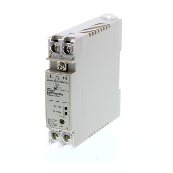
S8VS Ordering Information ■ List of Models Note: For details on normal stock models, contact your nearest OMRON representative. Without Indication Monitor (Standard) Power ratings Input voltage Output voltage Output current Model number 15 W 100 to 240 VAC 2.0 A S8VS-01505 (See note 1.) -
Page 4: Specifications
(approx. 140% to 190% of the rated output voltage). 5. To reset the protection, turn OFF the input power for three minutes or longer and then turn it back ON. http://www.ia.omron.com/ (c)Copyright OMRON Corporation 2007 All Rights Reserved. - Page 5 10.To ensure the emission rating, a ferrite ring core should be used in all cabling (TDK HF60T, HF70RH or equivalent model). 11.To ensure the emission rating, a ferrite ring core should be used in all cabling (SEIWA E04SR301334 or equivalent model). http://www.ia.omron.com/ (c)Copyright OMRON Corporation 2007 All Rights Reserved.
- Page 6 EN/VDE: EN50178 (=VDE0160), EN60950-1 (=VDE0805 Teil 1) SELV (EN60950/UL50178/UL60950-1) According to VDE0106/P100, IP20 SEMI F47-0200 (200-VAC input) Weight 550 g max. 850 g max. Note: Refer to page 5 for notes 1 to 11. http://www.ia.omron.com/ (c)Copyright OMRON Corporation 2007 All Rights Reserved.
- Page 7 EN60950-1 (VDE0805 Teil 1) According to VDE0106/P100, IP20 SELV (EN60950/UL50178/UL60950-1) According to VDE0106/P100, IP20 SEMI F47-0200 (200-VAC input) Weight 1,150 g max. 1,700 g max. Note: Refer to page 5 for notes 1 to 11. http://www.ia.omron.com/ (c)Copyright OMRON Corporation 2007 All Rights Reserved.
- Page 8 INPUT DC OUTPUT Noise filter −V AC (N) Rectifier/ Rectifier/smoothing circuit Inrush current smoothing protection circuit circuit Drive control circuit Overcurrent Current detection circuit circuit Voltage detection circuit Overvoltage detection circuit Photocoupler http://www.ia.omron.com/ (c)Copyright OMRON Corporation 2007 All Rights Reserved.
- Page 9 DC OUTPUT −V AC (N) Rectifier/smoothing circuit Rectification Smooth- −V Inrush current Harmonic protection current suppression circuit Drive control Overcurrent Current circuit detection circuit circuit Voltage detection circuit Overvoltage detection circuit Photocoupler http://www.ia.omron.com/ (c)Copyright OMRON Corporation 2007 All Rights Reserved.
- Page 10 Control circuit Drive circuit Voltage detection circuit Arithmetic Current operation detection circuit circuit Overcurrent circuit Rectifier/ Auxiliary power smoothing supply circuit circuit Sinking/Sourcing S8VS-48024A/B DC LOW Yrs/kh Display Switch circuit Photocoupler http://www.ia.omron.com/ (c)Copyright OMRON Corporation 2007 All Rights Reserved.
- Page 11 10 mm. In this case, reduce the corresponding derating curve by 5°C. −20 −10 70 80 Ambient temperature (°C) *1 Standard mounting *2 Face-up mounting/Horizontal mounting http://www.ia.omron.com/ (c)Copyright OMRON Corporation 2007 All Rights Reserved.
- Page 12 2. Internal parts may possibly deteriorate or be damaged if the Power Supply is used for applications with frequent inrush current or overloading at the load end. Do not use the Power Supply for such applications. http://www.ia.omron.com/ (c)Copyright OMRON Corporation 2007 All Rights Reserved.
- Page 13 3. S8VS-@@@24A@/B@ only. 4. S8VS-@@@24A@/B@ only (excluding S8VS-06024@). 5. Both sinking and sourcing outputs are available. 6. S8VS-@@@24A@ only (excluding S8VS-06024A). 7. S8VS-@@@24B@ only (excluding S8VS-06024B). Note: The S8VS-24024A is shown above. http://www.ia.omron.com/ (c)Copyright OMRON Corporation 2007 All Rights Reserved.
- Page 14 Note: 1. The fuse is located on the (L) side. It is NOT user replaceable. 2. This is the protective earth terminal specified in the safety standards. Always ground this terminal. 3. S8VS-48024A/B only. 4. S8VS-48024A only. 5. S8VS-48024B only. http://www.ia.omron.com/ (c)Copyright OMRON Corporation 2007 All Rights Reserved.
- Page 15 Note: 1. Press and hold the (9) Up Key U or (10) Down Key D for two seconds or more to increase or decrease the value rapidly. 2. The S8VS-06024@ is not provided with the setting mode and its parameters are fixed at the shipment setting. http://www.ia.omron.com/ (c)Copyright OMRON Corporation 2007 All Rights Reserved.
- Page 16 Key is pressed at the a01 display to return to the output current display, the a01 alarm will be cleared and the normal output display will return. 2. The above displays are for models with a maintenance forecast monitor (S8VS-@@@24A@). http://www.ia.omron.com/ (c)Copyright OMRON Corporation 2007 All Rights Reserved.
- Page 17 Replace the power supply if this condition occurs even if the output is correct, as internal parts may be deteriorated. 4. The “ ” error detection function is only for the S8VS-@@@24A@. http://www.ia.omron.com/ (c)Copyright OMRON Corporation 2007 All Rights Reserved.
- Page 18 ON (continuity at the maintenance forecast output terminal (Yrs)). 3. For details on the display, refer to Relationship between Indicated Values and Output of Set Values under Maintenance Forecast Monitor Function on page 19. http://www.ia.omron.com/ (c)Copyright OMRON Corporation 2007 All Rights Reserved.
- Page 19 4. The accuracy of the maintenance forecast function may be taken as the maximum period of the maintenance forecast. adversely affected by applications in which the AC input is frequently turned ON/OFF. http://www.ia.omron.com/ (c)Copyright OMRON Corporation 2007 All Rights Reserved.
- Page 20 (kh)) will output the status externally. (Alarm set value reached = OFF, i.e., no continuity at the total run time output terminal (kh)) The alarm set value can be changed in the setting mode. http://www.ia.omron.com/ (c)Copyright OMRON Corporation 2007 All Rights Reserved.
-
Page 21: Engineering Data
2. Internal parts may possibly deteriorate or be damaged if the Power Supply is used for applications with frequent inrush current or overloading at the load end. Do not use the Power Supply for such applications. http://www.ia.omron.com/ (c)Copyright OMRON Corporation 2007 All Rights Reserved. - Page 22 Detection value of Undervoltage Output alarm voltage Undervoltage output Main display Operation Lowest value of Voltage indication mode output voltage Note: Operation begins after about three seconds since the AC power is supplied. http://www.ia.omron.com/ (c)Copyright OMRON Corporation 2007 All Rights Reserved.
- Page 23 Note: The illustration is the S8VS-12024A model. S8VS-18024 (180 W) S8VS-18024@@ (180 W) 125.3 120.3 34.9 Rail stopper (Sliding: 15 max.) Screwless block (2.5-mm pitches) Note: The illustration is the S8VS-18024A model. http://www.ia.omron.com/ (c)Copyright OMRON Corporation 2007 All Rights Reserved.
-
Page 24: End Plate
M4 spring washer Note: If there is a possibility that the Unit will be subject to vibration or shock, use a steel DIN Rail. Otherwise, metallic filings may result from aluminum abrasion. http://www.ia.omron.com/ (c)Copyright OMRON Corporation 2007 All Rights Reserved. - Page 25 Front-mounting Bracket S82Y-VS10F (For 60-, 90-, 120-, (For 240-W type) (For 60-, 90-, 120-, 180-, 180-W types) and 240-W models) 4.5 dia. ±0.1 ±0.1 *Use two S82Y-VS10F brackets for the 240-W type. http://www.ia.omron.com/ (c)Copyright OMRON Corporation 2007 All Rights Reserved.
-
Page 26: Safety Precautions
The internal parts may occasionally deteriorate and be broken due to adverse heat radiation. Do not loosen the screw on the side face of the main body. http://www.ia.omron.com/ (c)Copyright OMRON Corporation 2007 All Rights Reserved. -
Page 27: Periodic Check
To prevent the generation of impulse voltages, reduce the applied voltage slowly with a variable resistor on the test device or turn the voltage ON and OFF at the zero-cross point. http://www.ia.omron.com/ (c)Copyright OMRON Corporation 2007 All Rights Reserved. - Page 28 ALL DIMENSIONS SHOWN ARE IN MILLIMETERS. To convert millimeters into inches, multiply by 0.03937. To convert grams into ounces, multiply by 0.03527. In the interest of product improvement, specifications are subject to change without notice. http://www.ia.omron.com/ (c)Copyright OMRON Corporation 2007 All Rights Reserved.
- Page 29 Warranty and Limitations of Liability WARRANTY OMRON's exclusive warranty is that the products are free from defects in materials and workmanship for a period of one year (or other period if specifi ed) from date of sale by OMRON. OMRON MAKES NO WARRANTY OR REPRESENTATION, EXPRESS OR IMPLIED, REGARDING NON-INFRINGEMENT, MERCHANTABILITY, OR FITNESS FOR PARTICULAR PURPOSE OF THE PRODUCTS.
Need help?
Do you have a question about the S8VS Series and is the answer not in the manual?
Questions and answers