Table of Contents
Advertisement
Quick Links
3104092-7B (Side-A)
MODEL
SWITCHING
POWER SUPPLY
スイッチング
形
パワーサプライ
INSTRUCTION MANUAL
EN
取扱説明書
JPN
Thank you for purchasing the S8VK-X.
This Instruction Manual describes the functions, performance, and application
methods required to use the S8VK-X.
• Make sure that a specialist with electric knowledge operates the S8VK-X.
• Read and understand this Instruction Manual, and use the product with enough
understanding.
Keep this Instruction Manual close at hand and use it for reference during operation.
この度は、 S8VK-X をお買い上げいただきまして、 まことにありがとうございます。
この取扱説明書では、 S8VK-X を使用する上で、 必要な機能、 性能、 使用方法などの情
報を記載しております。
S8VK-X をご使用に際して以下のことを守ってください。
• S8VK-X は電気の知識を有する専門家が扱ってください。
• この取扱説明書をよくお読みになり、 十分にご理解のうえ、 正しくご使用ください。
この取扱説明書はいつでも参照できるよう大切に保管してください。
OMRON Corporation
SHIOKOJI HORIKAWA, Shimogyo-Ku, Kyoto, 600-8530 Japan
©All Rights Reserved
For details on the communications and setting method, Switching Power Supply S8VK-X-series
Communications Manual (Cat. No. T213). You can download the Communications Manual
free-of-charge from the following OMRON web page: (http://www.ia.omron.com/)
通信機能、設定方法の詳細は「スイッチングパワーサプライ 形 S8VK-X 通信マニュアル」
(Man.No.SGTC-703)をご覧ください。
通信マニュアルはオムロンの下記の Web ページから無料でダウンロードすることができます。
(http://www.fa.omron.co.jp/)
EN
Key to Warning Symbols
Indicates a potentially hazardous situation which, if not avoided, could
WARNING
result in death or serious injury. Additionally, there may be severe
property damage.
Indicates a potentially hazardous situation which, if not avoided, may
CAUTION
result in minor or moderate injury or in property damage.
Warning Symbols
WARNING
If a wire become disconnected from the terminal block, electric shock may occur.
When connect the wires to the terminal block, insert the solid wire or ferrule straight
into the terminal block until the end strikes the terminal block.
CAUTION
• Minor electric shock, fire, or Product failure may occasionally occur. Do not
disassemble, modify, or repair the Product or touch the interior of the Product.
• Minor burns may occasionally occur. Do not touch the Product while power is being
supplied or immediately after power is turned OFF.
• Minor injury due to electric shock may occasionally occur. Do not touch the
terminals while power is being supplied.
Working voltage can be 370 V max. inside. This voltage can be also available 30 s
after the switch off.
• Minor electric shock, fire, or Product failure may occasionally occur. Do not allow
any pieces of metal or conductors or any clippings or cuttings resulting from
installation work to enter the Product.
JPN
警告表示の意味
正しい取り扱いをしなければ、この危険のために、軽傷・中程度の傷害
警告
を負ったり万一の場合には重傷や死亡に至ったりする恐れがあります。
また、同様に重大な物的損害をもたらす恐れがあります。
正しい取扱いをしなければ、この危険のために、時に軽傷・中程度の傷害
注意
を負ったり、あるいは物的損害を受ける恐れがあります。
• 警告表示
警告
電線が抜け感電の恐れがあります。
端子台に接続するときは、単線またはフェルール端子の先端が端子台に突き当たるまで
まっすぐ挿入してください。
注意
• 軽度の感電、発火、機器の故障が稀に起こる恐れがあります。分解、改造、修理し
たり、内部に触らないでください。
• 軽度の火傷が稀に起こる恐れがあります。通電中や電源を切った直後は製品本体に
触らないでください。
• 感電により軽度の傷害が稀に起こる恐れがあります。通電中は端子に触らないでく
ださい。通電時、本体内部には最大370Vの電圧が発生しています。電源OFF後も
30秒間この電圧が残留します。
• 軽度の感電、発火、機器の故障が稀に起こる恐れがあります。製品の中に金属、導線
または、取り付け加工中の切粉などが入らないようにしてください。
各部の名称 / Nomenclature
⑥⑦⑧⑨⑩
⑥⑦⑧⑨⑩
⑪
⑫
⑪
⑫
⑯
⑬
⑯
⑬
⑱
⑲
⑱
⑲
⑰
⑰
①②③④⑤
①②③④⑤
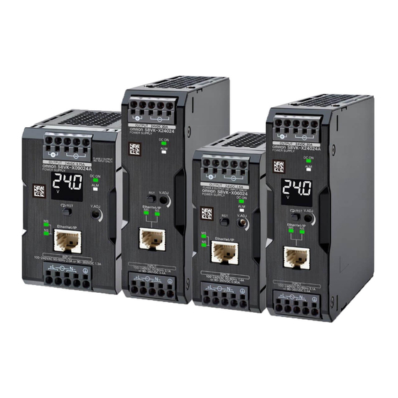
S8VK-X03005-EIP
S8VK-X09024-EIP
S8VK-X24024-EIP
S8VK-X060
-EIP
S8VK-X12024-EIP
S8VK-X48024-EIP
The S8VK-X060
-EIP is shown in the full
The S8VK-X24024-EIP is shown in the full
view drawing.
view drawing.
外形図は、 S8VK-X060
-EIPを使用 しています。
外形図は、 S8VK-X24024-EIPを使用 しています。
⑥⑦⑧⑨⑩
⑥⑦⑧⑨⑩
⑪
⑭
⑭
⑫
⑮
⑮
⑯
⑯
⑬
⑱
⑱
⑲
⑰
①②③④⑤
①②③④⑤
S8VK-X09024A-EIP
S8VK-X24024A-EIP
S8VK-X12024A-EIP
S8VK-X48024A-EIP
-EIP
The S8VK-X24024A
is shown in the full
view drawing.
外形図は、 S8VK-X24024A-EIPを使用 しています。
Nomenclature
EN
①, ② Input terminal (L),
⑬ Output voltage adjuster (V.ADJ)
(The fuse is located on the (L) side.)
⑭ Main display
③, ④ Input terminal (N)
⑮ Operation display
⑤ PE (protective earthing) terminal (
)
⑯ Switching display and reset key (for models with
(A PE (protective earthing) terminal
indication monitor)
stipulated in the safety standards is used.
Reset key (for models without indication monitor)
Connect fully to ground.)
⑰ EtherNet/IP port
⑥, ⑦ DC output terminal (+V)
⑱ Module status indicator (MS: green/red)
⑧, ⑨, ⑩ DC output terminal (-V)
⑲ Network status indicator (NS: green/red)
⑪ Output indicator (DC ON: green)
⑫ ALARM indicator (ALM: red)
各部の名称
JPN
①、 ② 入力端子 (L) ヒューズは (L) 側に挿入されています。
⑬ 出力電圧調整トリマ(V.ADJ)
③、 ④ 入力端子(N)
⑭ メイン表示部
⑤ PE(保護接地)端子( )
⑮ 動作表示部
/
(安全規格で定められた PE (保護接地) 端子のため、
⑯ 表示切替
リセットキー (表示モニタ付きタイプ)
アースは完全に接続してください。 )
リセットキー(表示モニタなしタイプ)
⑥、 ⑦ 直流出力端子(+V)
⑰ EtherNet/IP ポート
⑧、 ⑨、 ⑩ 直流出力端子(-V)
⑱ モジュールステータス表示灯(MS:緑 / 赤)
⑪ 出力表示灯(DC ON:緑)
⑲ ネットワークステータス表示灯 (NS : 緑 / 赤)
⑫ アラーム表示灯(ALM:赤)
Standard mounting /
Mounting / 取り付け方法について
Fig. 3
Fig. 2
標準取り付け状態
* 1
* 1
*3
*3
* 1
* 1
* 1
Precautions for Safe Use
EN
Installing/Storage Environment
•
• When storing the product for a long-term, ensure that the following conditions are satisfied to
maintain the performance of the replacement calculation function.
humidity of 25% to 70%.
• Take adequate measures to ensure proper heat dissipation to increase the long-term
reliability of the Product.
The Product is cooled by natural convection. Mount it so that air convection will occur around it.
1 Direction of air circulation
2 Space above and below the Product: 25 mm min.
(S8VK-X03005-EIP, X060
-EIP, X09024 -EIP, X12024 -EIP)
Space above and below the Product: 23 mm min. (S8VK-X24024 -EIP, X48024 -EIP)
3 Horizontal separation 0 mm or more
• A different derating curve from the one for the standard mounting must be used if the horizontal
separation is less than 15 mm.
• The internal parts may occasionally deteriorate or be damaged. Do not use the Product in
areas outside the derating curves.
• Use the Product at a humidity of 95% or less.
• Avoid places where the product is subjected to direct sunlight.
• Do not use the Product in locations where liquids, foreign matter, or corrosive gases may enter
the interior of the Product.
• Avoid places subject to shock or vibration. A device such as a contact breaker may be a vibration source.
Install the Product away from contactors and other parts and devices that are sources of vibration.
• If the Product is used in an area with excessive electronic noise or surge, be sure to separate
the Product as far as possible from the noise and surge sources.
• The internal parts may occasionally deteriorate and be broken due to adverse heat radiation.
Do not loosen the screws on the Product.
Installation/Wiring
• Connect the ground completely. A protective earthing terminal stipulated in safety standards is
used. Electric shock or malfunction may occur if the ground is not connected completely.
• Minor fire may possibly occur. Ensure that input and output terminals are wired correctly.
• To prevent wiring materials from smoking or ignition, confirm wire ratings and use the wiring
materials given in the following table.
Recommend Wire Type:
Terminal
Model
S8VK-X03005-EIP to X12024 -EIP
S8VK-X24024 -EIP
Input
S8VK-X48024 -EIP
S8VK-X03005-EIP, X06012-EIP
S8VK-X06024-EIP, X09024 -EIP
S8VK-X12024 -EIP
Output
S8VK-X24024 -EIP
S8VK-X48024 -EIP
PE (protective earthing)
S8VK-X03005-EIP to X48024 -EIP
Note: Use copper stranded or solid wires.
Stripping length
Recommend Wire Type
Ferrules length
8 mm
2
0.34 to 1.5 mm
/AWG22 to 16
10 mm
2 to 2.5 mm
2
/AWG14
10 mm
3.5 mm
2
/AWG12
12 mm
2
12 mm
6 mm
/AWG10
• When you insert wires or insert a flat-blade screwdriver into a release hole, do not press down
on the terminal block with a force of 40 N or greater.
• Do not wire anything to the release holes.
• Do not tilt or twist a flat-blade screwdriver while it is inserted into a release hole on the terminal
block. The terminal block may be damaged.
• Insert a flat-blade screwdriver into the release holes at an angle. The terminal block may be
damaged if you insert the screwdriver straight in.
• Do not allow the flat-blade screwdriver to fall out while it is inserted into a release hole.
• Do not bend a wire past its natural bending radius or pull on it with excessive force.
Doing so may cause the wire disconnection.
• Do not insert more than one wire into each terminal insertion hole.
• Do not pre-solder the ends of the wires. Doing so will inhibit proper connection.
• If there is a possibility that the Unit will be subject to vibration or shock, use Wires with Ferrules
or Stranded Wires.
• Be sure to remove the sheet covering the product for machining before power-on.
Output Voltage Adjustment
• The output voltage adjuster (V. ADJ) may possibly be damaged if it is turned with unnecessary
force. Do not turn the adjuster with excessive force.
• After completing output voltage adjustment, be sure that the output power or output current
does not exceed the rated output power or rated output current.
See the product catalog for details.
Suitability for Use
EN
Omron Companies shall not be responsible for conformity with any standards, codes or
regulations which apply to the combination of the Product in the Buyer' s application or use
of the Product. At Buyer' s request, Omron will provide applicable third party certification
documents identifying ratings and limitations of use which apply to the Product. This
information by itself is not sufficient for a complete determination of the suitability of the
Product in combination with the end product, machine, system, or other application or use.
Buyer shall be solely responsible for determining appropriateness of the particular Product
with respect to Buyer' s application, product or system. Buyer shall take application
responsibility in all cases.
NEVER USE THE PRODUCT FOR AN APPLICATION INVOLVING SERIOUS RISK TO
LIFE OR PROPERTY OR IN LARGE QUANTITIES WITHOUT ENSURING THAT THE
SYSTEM AS A WHOLE HAS BEEN DESIGNED TO ADDRESS THE RISKS, AND THAT
THE OMRON PRODUCT(S) IS PROPERLY RATED AND INSTALLED FOR THE
INTENDED USE WITHIN THE OVERALL EQUIPMENT OR SYSTEM.
安全上の要点
JPN
● 設置・保管環境について
・ 周囲温度 -40 ∼ +85℃、相対湿度 95% 以下で保管してください。
・ 交換時期演算機能の性能を維持するため、長期の保管は次の条件を満たしてください。
保管が 3 ヶ月以上超える場合は、温度 -25℃∼ +30℃、相対湿度 25 ∼ 70% で保管してください。
・ 取り付けにあたっては、機器の長期信頼性を向上させるために、放熱に十分留意してくださ
い。自然対流方式ですので、製品周囲の空気が対流するように取り付けてください。
* 1 空気の対流
* 2 上下間隔 25mm 以上
(形 S8VK-X03005-EIP、X060□□-EIP、X09024□-EIP、X12024□-EIP)
上下間隔 23mm 以上(形 S8VK-X24024□-EIP、X48024□-EIP)
* 3 左右間隔 0mm 以上
・ 左右間隔 15mm 未満時は、標準取り付け時とはディレーティング曲線が異なります。
・ 内部部品の劣化・破損が稀に起こる恐れがありますので、取り付けごとのディレーティング
曲線の範囲を超える状態では使用しないでください。
・ 相対湿度が 95% 以下の場所で使用してください。
Fig.1
・ 直射日光の当たる場所では使用しないでください。
・ 製品内に液体や異物、腐食性ガスが入る可能性のある場所では使用しないでください。
・ 振動・衝撃の激しい場所では使用しないでください。特にコンタクタなど振動源となる部品
や装置から離して設置してください。
・ 強い高周波ノイズやサージを発生する機器からは離して取り付けてください。
・ 放熱性の悪化により稀に内部部品が劣化・破損する恐れがあります。製品本体のねじを緩め
ないでください。
● 設置・配線について
・ アースは完全に接続してください。安全規格で定められた PE(保護接地)端子のため、 アー
スが不完全な場合感電や誤動作の恐れがあります。
・ 軽度の発火が万一の場合起こる恐れがありますので、入出力端子など誤配線のないようにご
注意ください。
・ 配線材の発煙・発火を防ぐために、電線の定格をご確認の上、下表の線材をご使用ください。
推奨電線
端子
形式
形S8VK-X03005-EIP∼X12024□-EIP
形S8VK-X24024□-EIP
入力
形S8VK-X48024□-EIP
形S8VK-X03005-EIP、X06012-EIP
形S8VK-X06024-EIP、X09024□-EIP
出力
形S8VK-X12024□-EIP
形S8VK-X24024□-EIP
形S8VK-X48024□-EIP
⑪
PE(保護接地)
形S8VK-X03005-EIP∼X48024□-EIP
⑫
注:線材は銅製で、より線か単線をご使用ください。
⑬
被覆剥きしろ
⑲
フェルール 端子
推奨電線
導体長さ
⑰
フ ェルール端子使用時
8 mm
0.34∼1.5mm
2
/AWG22∼16
10 mm
2∼2.5mm
2
/AWG14
10 mm
3.5mm
2
/AWG12
12 mm
6mm
2
/AWG10
12 mm
・ 配線挿入時またはリリースホールへのマイナスドライバ挿入時に 40N 以上の力で端子台を押
さえつけないでください。
・ リリースホールには配線しないでください。
・ リリースホールにマイナスドライバを押し込んだ状態で、マイナスドライバを傾けたり、ね
じったりしないでください。端子台が破損する恐れがあります。
・ リリースホールにマイナスドライバを押し込むときは斜めにして入れてください。まっすぐ
に入れた場合は端子台が破損する恐れがあります。
・ リリースホールに押し込んだマイナスドライバを落下させないようにご注意ください。
・ 電線は無理に曲げたり、引っぱったりしないでください。断線する恐れがあります。
・ 端子(挿入)穴1つに複数の電線を挿入しないでください。
Fig.1
・ 電線の先端を予備はんだしないでください。正しい接続ができなくなります。
・ 振動 ・ 衝撃のかかる可能性のある場合は、フェルール端子付き電線、より線をご使用ください。
・ 通電前には、加工時に覆ったシートなどを必ず取り外して放熱に支障がないことをご確認く
ださい。
● 出力電圧調整について
・ 出力電圧調整トリマ(V.ADJ)の破損が万一の場合起こる恐れがありますので、必要以上に
強い力を加えないでください。
・ 出力電圧調整後の出力電力、出力電流は定格出力電力、定格出力電流以下にしてください。
● 詳細はカタログを参照してください。
Fig.1
JPN
ご承諾事項
当社商品は、一般工業製品向けの汎用品として設計製造されています。従いまして、次に掲げる用途
での使用を意図しておらず、お客様が当社商品をこれらの用途に使用される際には、当社は当社商品
に対して一切保証をいたしません。ただし、次に掲げる用途であっても当社の意図した特別な商品用
* 1
途の場合や特別の合意がある場合は除きます。
*2
(a) 高い安全性が必要とされる用途(例:原子力制御設備、燃焼設備、航空・宇宙設備、鉄道設備、
昇降設備、娯楽設備、医用機器、安全装置、その他生命・身体に危険が及びうる用途)
(b) 高い信頼性が必要な用途(例:ガス・水道・電気等の供給システム、24 時間連続運転システム、
決済システムほか権利・財産を取扱う用途など)
(c) 厳しい条件または環境での用途(例:屋外に設置する設備、化学的汚染を被る設備、電磁的妨害
を被る設備、振動・衝撃を受ける設備など)
(d) カタログ等に記載のない条件や環境での用途
*(a) から (d) に記載されている他、本カタログ等記載の商品は自動車(二輪車含む。以下同じ)向け
ではありません。自動車に搭載する用途には利用しないで下さい。自動車搭載用商品については当
社営業担当者にご相談ください。
*2
*上記は適合用途の条件の一部です。 当社のベスト、総合カタログ、データシート等最新版のカタログ、
マニュアルに記載の保証・免責事項の内容をよく読んでご使用ください。
Precautions for Correct Use
EN
Mounting
• For mounting types other than Fig. 2, refer to the catalog.
Input Voltage Tolerance
Rating:
100 to 240 VAC
• Mains supply tolerance for AC input: -15 to +10% (85 to 264 VAC)
Fig.3
• 100 VAC with 100% load and 85 VAC with 85% load
• When using an input voltage less than 100 VAC, reduce the load calculated with derating
1%/VAC.
Output Voltage Adjustment
Default Setting: Set at the rated voltage
Adjustment Range: The output voltage can be adjusted to between -10% to +16.7% of the rated
voltage with the voltage output adjuster "V.ADJ" (⑬) on the front panel.
(excluding the S8VK-X09024 -EIP.)
Turning clockwise increases the output voltage, and turning counterclockwise decreases the
output voltage.
Notes:
The output voltage may increase beyond the allowable voltage range when "V.ADJ" (⑬)
operation is performed. When adjusting the output voltage, check the output voltage of the
Product and be sure that the load is not destroyed.
Dielectric Strength Test
The Product is designed to withstand 3,000 VAC for one minute between input terminals ① to ④
together and output terminals ⑥ to ⑩ together. When conducting the test, set the cutoff current
for the withstand voltage test device to 20 mA.
Notes:
• If a tester switch is used to apply or cut off 3,000 V suddenly, the resulting impulse voltage
may occasionally destroy the Product.
Increase/decrease test voltage gradually.
• Be sure to short-circuit all the output terminals of the product to protect the product from
damage.
Insulation Resistance Test
When testing the insulation resistance of the product, use a DC ohmmeter at 500 VDC.
Note:
Recommend Wire Type
Be sure to short-circuit all the output terminals of the product to protect the product from damage.
(mm
2
)
(AWG)
Overload Protection
0.34 to 2.5
22 to 14
0.5 to 2.5
20 to 14
The load and the Product are automatically protected from overcurrent damage by the overload
protection function. When the current returns to within the rated range, the Product will
0.75 to 2.5
18 to 14
automatically return to normal operation.
0.75 to 2.5
18 to 14
20 to 14
Notes:
0.5 to 2.5
• Internal parts may possibly deteriorate or be damaged if a shortcircuited, overload, or boost
0.75 to 2.5
18 to 14
load state continues during operation.
2 to 2.5
14
• Internal parts may possibly deteriorate or be damaged if the Product is used for applications
3.5 to 6
12 to 10
with frequent inrush current or overloading at the load end. Do not use the Product for such
2 to 2.5
14
applications.
Overvoltage Protection
This product automatically protects itself and the load from overvoltage.
Recommend Stripping length
Overvoltage protection is activated if the output voltage rises above approx. 130% (110% on the
Ferrules used
Ferrules not used
S8VK-X09024 -EIP only) of the rated output voltage.
10 mm
8 mm
To reset the product, leave the product off for more than 3 minutes and then turn it on again.
12 mm
8 mm
Note:
12 mm
10 mm
Be sure to clear the cause of the overvoltage, before turning on the product.
14 mm
15 mm
Replacement Calculation Function
16 mm
15 mm
When the product is used in an application that involves frequent and repeated ON/OFF of the
input voltage, the accuracy of the replacement calculation function and the total run time may be
degraded.
Communications
• Communications settings are required at installation or replacing the product. Set the settings
correctly according to the communications manual.
• For the EtherNet/IP or Modbus TCP connection method and the cables to be used, follow the
information of the S8VK-X communications manual. Otherwise, communications may be faulty.
• Do not exceed the communications distance that is given in the specifications.
• If EtherNet/IP tag data links (cyclic communications) are used with a repeating hub, the
communications load on the network will increase. This will increase collisions and may
prevent stable communications.
Do not use repeating hubs on networks where tag data links are used. Use an Ethernet switch
instead.
• Do not pull on the communications cables or bend the cables beyond their natural limit. Do not
place heavy objects on top of the communications cables or other wiring lines. Doing so may
cause the wire to break.
• To avoid inductive noise, keep the communications cables away from power cables carry high
voltages or large currents. Also, do not wire power lines together with or parallel to product
wiring.
• If you do not connect the communications cable, always attach the dust cover.
• Depending on the ambient temperature or load ratio, the Power Supply may get extremely hot.
In that case, minor burns may occur. Do not insert and remove communications cables.
Conformance to EU Directives
Refer to the catalog and this instruction manual for details on the operating condition for
compliance with the EMC Directive.
Connecting Wires to the Push-In Plus Terminal Block
• Part Names of the Terminal Block
• Connecting Wires with Ferrules and Solid Wires
Insert the solid wire or ferrule straight into the terminal
block until the end strikes the terminal block.
If a wire is difficult to connect because it is too thin, use
a flat-blade screwdriver in the same way as when
connecting stranded wire.
JPN
● 取り付けについて
・ Fig.2 の標準取り付けの他はカタログを参照してください。
● 入力電圧について
定格:
AC100 ∼ 240V
・ AC 入力時: -15% ∼ +10%(AC85 ∼ 264V)
Fig.3
・ AC100V で 100% 負荷、AC85V で 85% 負荷
・ AC100V 未満は、AC1%/V のディレーティングをかけて負荷を軽減してください。
● 出力電圧調整について
出荷時:定格電圧にセットしています。
調整範囲:前面の「V.ADJ」(⑬) により定格電圧の -10% ∼ +16.7% の範囲で調整が可能です。
(形 S8VK-X09024□-EIP を除く)
右に回すと出力電圧は上がり、左に回すと出力電圧は下がります。
注:V.ADJ (⑬) の操作によっては、出力電圧が電圧可変範囲以上に上昇します。出力電圧を調
整する場合は、製品の出力電圧を確認し負荷を破壊させないようご注意ください。
● 耐電圧試験
製品の<入力一括①∼④>と<出力⑥∼⑩>間は AC3000V、1 分間に耐えるように設計され
ています。試験を実施する場合、耐電圧試験機のカットオフ電流は 20mA に設定して実施して
ください。
注:
・ 試験機のスイッチでいきなり 3000V を印加または遮断すると発生するインパルス電圧によ
り万一の場合、製品が破損することがあります。印加電圧は試験機のボリュームで徐々に
変化させてください。
・ 試験時は製品の破損防止のため、必ずすべての端子を短絡してください。
● 絶縁抵抗試験
絶縁抵抗試験を実施する場合は、DC 絶縁抵抗計(DC500V)をご使用ください。
注:試験時は製品の破損防止のため、必ずすべての端子を短絡してください。
● 過電流保護機能
過電流保護回路により、 短絡 ・ 過電流に対して自動的に出力電圧を低下させ、 機器を保護します。
推奨電線
過電流状態が解除されると、製品は自動的に正常運転に復帰します。
(mm
2
)
(AWG)
注:
0.34∼2.5
22∼14
・ 短絡および過電流状態での使用が継続されますと稀に内部部品の劣化・破損となる場合が
0.5∼2.5
20∼14
ありますので、ご注意ください。
0.75∼2.5
18∼14
・ 万一の場合、内部部品の劣化・破損が考えられますので、負荷側の突入電流、過負荷状態
0.75∼2.5
18∼14
が頻繁に発生するアプリケーションには使用しないでください。
0.5∼2.5
20∼14
0.75∼2.5
18∼14
● 過電圧保護機能
14
2∼2.5
定格出力電圧の約 130% 以上(形 S8VK-X09024□-EIP のみ約 110% 以上) 電圧を出力し
12∼10
3.5∼6
た場合、 出力電圧を遮断し、 過電圧による負荷の破損を防止します。復帰は入力電源を OFF し、
2∼2.5
14
3 分以上放置後、入力電源を再投入してください。
注:入力電源の再投入は、必ず原因を取り除いた後に行ってください。
● 交換時期演算機能について
推奨被覆剥き しろ
入力電圧の ON,OFF を頻繁に繰り返すアプリケーションでは交換時期演算機能および積算稼
フ ェルール端子未使用時
働時間の精度が悪化する場合があります。
10 mm
8 mm
● 通信について
12 mm
8 mm
・ 設置・交換時には通信設定が必要です。通信マニュアルに従って正しく設定してください。
12 mm
10 mm
・ EtherNet/IP、Modbus TCP の接続方法や使用するケーブルは、通信マニュアルのとおりに
14 mm
15 mm
してください。通信不良になる恐れがあります。
16 mm
15 mm
・ 通信距離は仕様範囲内でご使用ください。
・ リピータハブを使用して EtherNet/IP のタグデータリンク通信(サイクリック通信)を行う
と、ネットワークの通信負荷が高まるため、コリジョン(衝突)が多数発生し、安定した通
信ができなくなります。タグデータリンクを利用するネットワークでは、必ずスイッチング
ハブを使用してください。
・ 通信ケーブルを無理に曲げたり、引っ張ったりしないでください。通信ケーブルのコード部
に重いものを載せないでください。断線する恐れがあります。
・ 誘導ノイズを防止するために、通信ケーブルは高電圧、大電流の動力線とは分離して配線し
てください。また、動力線との並行配線や同一配線を避けてください。
・通信ケーブルを接続しない場合はダストカバーをつけてください。
・周囲温度や負荷率によっては、製品本体が高温になることがあります。その場合、軽度の火
傷の恐れがありますので、通信ケーブルを挿抜しないでください。
● EU 指令への適合について
EMC 指令に適合するためのご使用条件については、 カタログ、 この取扱説明書を参照ください。
● プッシュイン Plus 端子台への接続
・ 端子台の各部の名称
・ 圧着棒端子(以降フェルール端子)付き電線、
単線の接続方法
端子台に接続するときは、単線またはフェルール端子
の先端が端子台に突き当たるまでまっすぐ挿入してく
ださい。
細い単線で接続しにくい場合は、より線の接続方法同
様にマイナスドライバを使用してください。
Use the following procedure to connect the wires to the
terminal block.
1. Hold a flat-blade screwdriver at an angle and insert it
into the release hole.
Fig.2
The angle should be between 10° and 15°.
If the flat-blade screwdriver is inserted correctly, you will
feel the spring in the release hole.
2. With the flat-blade screwdriver still inserted into the
release hole, insert the wire into the terminal hole until it
strikes the terminal block.
3. Remove the flat-blade screwdriver from the release
hole.
• After the insertion, pull gently on the wire to make sure that it will not come off and the
wire is securely fastened to the terminal block.
• If you use a ferrule with a conductor length of 10 mm, part of the conductor may be
visible after the ferrule is inserted into the terminal block, but the product insulation
distance will still be satisfied.
Removing Wires from Push-In Plus Terminal Block
Use the following procedure to remove wires from the
terminal block.
The same method is used to remove stranded wires, solid
wires, and ferrules.
1. Hold a flat-blade screwdriver at an angle and insert it
into the release hole.
2. With the flat-blade screwdriver still inserted into the
release hole, remove the wire from the terminal
insertion hole.
3. Remove the flat-blade screwdriver from the release
hole.
Recommended Flat-blade Screwdriver
Use a flat-blade screwdriver to connect and remove wires.
Use the flat-blade screwdriver shown at right.
EN50178
•
DC output terminals (⑥ to ⑩) are galvanically
isolated from the input terminals (① to ④).
•
Overvoltage category III.
•
This equipment is for protection class I.
•
Climatic class: 3K3
:According to EN50178.
UL60950-1, UL62368-1
EN60950-1, EN62368-1
According to Overvoltage category II.
EN61558-2-16/IEC61558-2-16
Matters related to EN61558-2-16/IEC61558-2-16
•
Switch mode power supply (SMPS) :
•
Short-circuit-proof safety isolating
transformer:
Ambient temperature / Surrounding
Air Temperature
Max. 55°C at 80% load, 40°C at 100% load
(>40°C Load derating: 1.33%/K)
Compliance with Class I Division 2 Hazardous Location:
SUITABLE FOR USE IN CLASS I, DIVISION 2, GROUPS A, B, C AND D HAZARDOUS
LOCATIONS, OR NONHAZARDOUS LOCATIONS ONLY.
WARNING - EXPLOSION HAZARD - DO NOT DISCONNECT EQUIPMENT WHILE THE CIRCUIT
IS LIVE OR UNLESS THE AREA IS KNOW TO BE FREE OF IGNITABLE CONCENTRATIONS.
WARNING - EXPLOSION HAZARD - SUBSTITUTION OF ANY COMPONENT MAY IMPAIR
SUITABILITY FOR CLASS I, DIVISION 2.
THESE DEVICES ARE OPEN-TYPE DEVICES THAT ARE TO BE INSTALLED IN AN
ENCLOSURE SUITABLE FOR THE ENVIRONMENT AND CAN ONLY BE ACCESSED
WITH THE USE OF A TOOL OR KEY.
Temperature Code:T3C
Terminal (Insertion)
hole
EtherNet/IP™ is trademarks of ODVA.
Modbus® is a registered trademark of Schneider Electric.
Release hole
Terminal (Insertion) hole
OMRON ELECTRONICS LLC
Phone: 1-800-55-OMRON
Phone: 1-847-843-7900
Fax
: 1-847-843-7787
UNITED KINGDOM
OMRON ELECTRONICS LTD.
Phone: 44-1908-258-258
Release hole
Ferrules
Fax
: 44-1908-258-158
and solid wires
使用上の注意
・ より線の接続方法
端子台に接続するときは、以下の手順により行ってく
ださい。
1. マイナス ドライバを斜めに し、 リ リ ースホールに押 し込んで
く だ さ い。
Fig.2
押 し込み角度は、 10° ∼15° が適切です。 マイナス ドライ
バを正 し く 押 し込む と、 リ リ ースホール内のバネの反発を
感じ ます。
2. リ リ ースホールにマイナス ドライバを押 し込んだ状態で、 電
線の先端が端子台に突き当たる までま っす ぐ挿入 して く
だ さ い。
3. マイナス ドライバを リ リ ースホールか ら抜いて く だ さ い。
・ 接続確認
・ 挿入後、 軽く引っ張って電線が抜けないこと (端子台に固定されていること) を確認してください。
・ 導体長さ 10mm フェルール端子を使用し、端子台に挿入後、導体部の一部が見える場
合もありますが、製品の絶縁距離は満足しています。
● プッシュイン Plus 端子台からの取り外し
電線を端子台から取り外すときは、以下の手順により
行ってください。
取り外し方法は、より線/単線/フェルール端子とも
同じです
。
1. マイナス ドライバを斜めに し、 リ リ ースホールに押 し込んで
く だ さ い。
2. リ リ ースホールにマイナス ドライバを押 し込んだ状態で、 電
線を端子 (挿入) 穴か ら抜いて く だ さ い。
3. マイナス ドライバを リ リ ースホールか ら抜いて く だ さ い。
● 推奨マイナスドライバ
電線の接続と取り外しには、マイナスドライバを使用し
ます。
マイナスドライバは、右記のものを使用してください。
● EN50178
・
直流出力端子 (⑥∼⑩) は、 入力端子 (①∼④)
と電気的に分離されています。
・
過電圧カテゴリ III
・
機器は保護クラスI
・
気候条件:3K3
以上 EN50178 に従います。
● UL60950-1、UL62368-1
EN60950-1、EN62368-1
過電圧カテゴリ II に従います。
● EN61558-2-16/IEC61558-2-16
注意事項
・
スイッチングモード電源 (SMPS) :
・
耐短絡安全絶縁変圧機:
● 使用周囲温度について
80%負荷で最大 55℃、 100%負荷で最大 40℃
40℃を超える場合は、 1.33%/K のディレー
ティングをかけて負荷を軽減してください。
EtherNet/IP™ は ODVA の商標です。
端子 (挿入) 穴
Modbus® は、Schneider Automation 社の登録商標です。
リ リ ースホール
オムロン株式会社
インダストリアルオートメーションビジネスカンパニー
端子 (挿入) 穴
OMRON Corporation
Shiokoji Horikawa, Shimogyo-ku, kyoto, 600-8530 Japan
●カスタマサポートセンタ
0120−919−066
携帯電話やPHS からのご利用は
電話 055-982-5015 (通話料がかかります)
【技術のお問い合わせ時間】
リ リ ースホール
フ ェルール端子
ま たは単線
営業時間:8:00∼21:00 営業日:365日
上記フリーコール以外の制御機器の技術窓口:
電話 055-982-5000 (通話料がかかります)
●FAX によるお問い合わせは下記をご利用ください。
カスタマサポートセンタ お客様相談室 FAX 055-982-5051
●インターネットによるお問い合わせは下記をご利用ください。
http://www.fa.omron.co.jp
●その他のお問い合わせ先
納期・価格・修理・サンプル・仕様書は貴社のお取引先、
または貴社担当オムロン営業員にご相談ください。
10 to 15°
Flat-blade screwdriver
2
3
1
10 to 15°
Flat-blade screwdriver
2
3
1
Side
Front
2.5 dia.
0.4 mm
2.5 mm
EN
Safety standards
Pollution degree
Use in pollution degree2 environment.
DC Input
Fig.1
• Safety standards apply for a DC input with
UL60950-1, UL62368-1, cUR (CSA C22.2
No.60950-1), cUR (CSA C22.2 No.62368-1),
EN/IEC 60950-1, EN/IEC 62368-1, and
EN/IEC 61558-2-16.
• Input voltage: 90 to 350 VDC (<140 VDC
load derating: 0.5%/V)
• To meet safety standards when you use a
DC input, use one of the following rated
fast-acting fuses on Positive side ((L) side).
S8VK-X03005-EIP (350 VDC min., 6 A)
S8VK-X06012-EIP (350 VDC min., 6 A)
S
S8VK-X06024-EIP (350 VDC min., 6 A)
S8VK-X09024 -EIP (350 VDC min., 8 A)
S8VK-X12024 -EIP (350 VDC min., 8 A)
S8VK-X24024 -EIP (350 VDC min., 8 A)
S8VK-X48024 -EIP (350 VDC min., 12 A)
Trademarks
EN
EN
Contact address
OMRON CANADA INC.
Phone: 1-416-286-6465
Phone: 1-866-986-6766
Fax
: 1-416-286-6648
363 6
TEL
02-2715-3331
10∼15°
マイナス ドライバ
2
3
1
10∼15°
マイナス ドライバ
2
3
1
側面
正面
φ2.5mm
0.4mm
2.5mm
安全規格
JPN
● 汚染度について
汚染度2の環境で使用してください。
● DC 入力時について
Fig.1
・
DC 入力時は UL60950-1、 UL62368-1、
cUR (CSA C22.2 No.60950-1) 、
cUR (CSAC22.2No.62368-1) 、
EN/IEC60950-1、 EN/IEC62368-1、 EN50178
EN/IEC61558-2-16 が安全規格対象となります。
・入力電圧:DC90 ∼ 350V
DC140V 未満は 0.5%/V ディレーティングを
かけて負荷を軽減してください。
・DC 入力時の安全規格要件を満足するため以下
S
の定格の速断型ヒューズを (L) 側に接続してご
使用ください。
S8VK-X03005-EIP (DC350V 以上、 6A)
S8VK-X06012-EIP (DC350V 以上、 6A)
S8VK-X06024-EIP (DC350V 以上、 6A)
S8VK-X09024□-EIP (DC350V 以上、 8A)
S8VK-X12024□-EIP (DC350V 以上、 8A)
S8VK-X24024□-EIP (DC350V 以上、 8A)
S8VK-X48024□-EIP (DC350V 以上、 12A)
JPN
商標
JPN
お問い合せ先
(フリーコール)
Advertisement
Table of Contents

Related Manuals for Omron S8VK-X


Summary of Contents for Omron S8VK-X
- Page 1 Product in the Buyer’ s application or use 警告 を負ったり万一の場合には重傷や死亡に至ったりする恐れがあります。 of the Product. At Buyer’ s request, Omron will provide applicable third party certification Contact address また、同様に重大な物的損害をもたらす恐れがあります。 documents identifying ratings and limitations of use which apply to the Product. This information by itself is not sufficient for a complete determination of the suitability of the •...
- Page 2 Type de fil recommandé Protection contre les surcharges Utiliser un tournevis plat pour connecter et déconnecter de communication de l'alimentation de commutation série S8VK-X (Cat. N° T213). Il est possible Modèle les fils. de télécharger le Manuel de communication gratuitement sur la page Web OMRON suivante : -EIP 0.34...
Need help?
Do you have a question about the S8VK-X and is the answer not in the manual?
Questions and answers