YASKAWA iC9200 Series Manual
Cpu
Hide thumbs
Also See for iC9200 Series:
- Operating manual (220 pages) ,
- Manual (62 pages) ,
- Product manual (138 pages)

Related Manuals for YASKAWA iC9200 Series


Summary of Contents for YASKAWA iC9200 Series
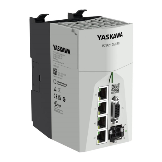
- Page 1 Series CPU | PMC921xEx | Manual HB700 | CPU | PMC921xEx | en | 23-06 IEC 61131 CPU iC921xM-x - Hardware...
- Page 2 YASKAWA Europe GmbH Philipp-Reis-Str. 6 65795 Hattersheim Germany Tel.: +49 6196 569-300 Fax: +49 6196 569-398 Email: info@yaskawa.eu Internet: www.yaskawa.eu.com PMC921xEx_000_CPU iC921xM-x,1,EN - © 2023...
-
Page 3: Table Of Contents
2.7.2 Device repairs and defects................35 2.8 Industrial security and installation guidelines..........36 2.8.1 Industrial security in information technology..........36 2.8.2 Installation guidelines.................. 38 2.9 General data for iC9200 Series..............41 2.9.1 Use in difficult operating conditions............. 42 Hardware description................... 43 3.1 Properties....................... 43 3.2 Structure...................... - Page 4 4.4.3 Create a new project................... 64 4.4.4 Online access to the CPU................64 4.5 Memory management..................67 4.5.1 Internal memory................... 67 4.5.2 Slot for Yaskawa SD card................69 4.6 MRESET and reset to factory settings............71 4.7 Firmware update..................... 73 4.8 Safe Mode...................... 73 4.9 Web-based management - WBM..............
-
Page 5: General
This material is protected by copyright laws. It may not be reproduced, distributed, or altered in any fashion by any entity (either internal or external to Yaskawa) except in accordance with applicable agreements, contracts or licensing, without the express written consent of Yaskawa and the business management owner of the material. -
Page 6: About This Manual
About this manual Technical support Contact your local representative of YASKAWA Europe GmbH if you encounter problems or have questions regarding the product. If such a location is not available, you can reach the YASKAWA customer service via the following contact: YASKAWA Europe GmbH, European Headquarters, Philipp-Reis-Str. -
Page 7: Safety Instructions
Series General Safety instructions 1.3 Safety instructions Intended use WARNING! Danger by non intended use! Any other use beyond the intended use and/or other use of this product can lead to dangerous situations and is prohibited. The CPU iC921xM-x is constructed and produced for: industrial use. -
Page 8: Basics And Mounting
Series Basics and mounting Safety notes for the user Basics and mounting 2.1 Safety notes for the user DANGER! Safety instructions Observe the following safety instructions! Disregarding these safety regu- lations may result in death, serious personal injury or damage to equip- ment. - Page 9 Series Basics and mounting Safety notes for the user Safety instructions for starting applications When configuring the start conditions for your plant, take into account: – The machine or plant may only be started when it has been ensured that no one is in the danger zone.
-
Page 10: System Conception
The iC9200 Series is a modular automation system for assembly on a 35mm mounting rail. Due to the compatibility to the System SLIO from Yaskawa you can adapt this system exactly to your automation tasks by using the System SLIO periphery modules in 2-, 4-, 8- and 16-channel versions. - Page 11 With the CPU iC921xM-x CPU electronics and power supply are integrated in one housing. The CPU is programmed and configured with iCube Engineer from Yaskawa in IEC 61131-3 . The CPU has a PCIe bus on the left for future expansions. On the right side via the SliceBus you can connect System SLIO periphery modules from Yaskawa.
- Page 12 Series Basics and mounting System conception > Components 8x periphery modules Each 8x periphery module consists of a terminal and an electronic module. Terminal module Electronic module Terminal module The terminal module serves to carry the electronic module, contains the backplane bus with power supply for the electronic, the DC 24V power section supply and the staircase- shaped terminal for wiring.
- Page 13 Series Basics and mounting System conception > Components Electronic unit The functionality of a 16x periphery module is defined via the terminal block, which is connected to the electronic unit via a secure flap mechanism. In the case of an error you can exchange the defective electronic unit for a functional unit with standing wiring.
-
Page 14: Hardware Revision
There is the possibility to fix the assignment of electronic and terminal module. Here coding pins (order number 000-0AC00) from Yaskawa can be used. The coding pin con- sists of a coding jack and a coding plug. By combining electronic and terminal module with coding pin, the coding jack remains in the electronic module and the coding plug in the terminal module. -
Page 15: Dimensions
Series Basics and mounting Dimensions 2.3 Dimensions CPU iC921xM-x All dimensions are in mm. 8x periphery module 76.5 12.9 electronic module 12.9 HB700 | CPU | PMC921xEx | en | 23-06... -
Page 16: Mounting
Series Basics and mounting Mounting > Mounting CPU 16x periphery module 76.5 12.9 2.4 Mounting WARNING! Unintentional machine start-up – Do not mount or dismount when the power is on! – Disconnect the device from the power supply before mounting or dis-... - Page 17 Series Basics and mounting Mounting > Mounting CPU Clack Proceeding Mount the mounting rail! Please consider that a clearance from the middle of the mounting rail of at least 105mm above and below exists. Turn the locking lever upwards, place the CPU at the mounting rail and turn the lever downward.
-
Page 18: Mounting Periphery Modules
Series Basics and mounting Mounting > Mounting periphery modules Assembly possibilities Horizontal hanging, vertical hanging or lying: 2.4.2 Mounting periphery modules When using System SLIO modules, you must always mount the power module 007-1AB00 - DC 24V 10A, because the CPU does not provide a power section supply due to the system. -
Page 19: Wiring
Series Basics and mounting Wiring Mounting periphery The procedure is identical for 8x and 16x periphery modules. modules Clack Mount the periphery modules you want. After mounting the whole system, to protect the backplane bus connectors at the last module you have to mount the bus cover, now. If the last module is a clamp module, for adaptation the upper part of the bus cover is to be removed. -
Page 20: Wiring Cpu
Series Basics and mounting Wiring > Wiring CPU 2.5.1 Wiring CPU CPU connector The CPU has a removable connector for the power supply. With the wiring of the con- nector a "push-in" spring-clip technique is used. This allows a quick and easy connection of your supply lines. -
Page 21: Wiring System Slio Periphery
Series Basics and mounting Wiring > Wiring System SLIO periphery Remove connector You have the option to remove the connector of the power supply, e.g. for a module change with fixed wiring. For this the connector has a locking lever. The connector is... - Page 22 Series Basics and mounting Wiring > Wiring System SLIO periphery Wiring proceeding Pin no. at the connector Opening for screwdriver Connection hole for wire Insert a suited screwdriver at an angel into the square opening as shown. Press and hold the screwdriver in the opposite direction to open the contact spring.
- Page 23 Series Basics and mounting Wiring > Wiring System SLIO periphery CAUTION! Since the power section supply is not internally protected, it is to be exter- nally protected with a fuse, which corresponds to the maximum current. This means max. 10A is to be protected by a 10A fuse (fast) respectively...
- Page 24 Series Basics and mounting Wiring > Wiring System SLIO periphery Wiring proceeding Pin no. at the connector Opening for screwdriver Connection hole for wire Insert a suited screwdriver at an angel into the square opening as shown. Press and hold the screwdriver in the opposite direction to open the contact spring.
- Page 25 Series Basics and mounting Wiring > Wiring System SLIO periphery 2.5.2.2.1 Wiring 16x periphery modules Terminal block connectors CAUTION! Do not connect hazardous voltages! If this is not explicitly stated in the corresponding module description, hazardous voltages are not allowed to be connected to the corresponding terminal block! The 16x periphery module has a removable terminal block for wiring.
- Page 26 Series Basics and mounting Wiring > Wiring System SLIO periphery Data 30V DC Cross section 0.08 ... 1.5mm (AWG 28 ... 16) Stripping length 10mm Wiring procedure Pin number at the connector Opening for screwdriver Connection hole for wire Insert a suited screwdriver at an angel into the square opening as shown.
- Page 27 Series Basics and mounting Wiring > Wiring System SLIO periphery Power module 007-1AB00 SysDC5V DC 24V DC 24V DC24V DC24V DC24V DC24V (1) DC 24V supply CPU: DC 5V electronic section supply I/O area (max. 2A) (2) Power module 007-1AB00: DC 24V power section supply (max.
-
Page 28: Demounting
Series Basics and mounting Demounting > Demounting CPU CAUTION! Since the power section supply is not internally protected, it is to be exter- nally protected with a fuse, which corresponds to the maximum current. This means max. 10A is to be protected by a 10A fuse (fast) respectively... - Page 29 Series Basics and mounting Demounting > Demounting CPU Turn the locking lever of the CPU to be mounted upwards, place the CPU at the mounting rail and turn the lever downward. Reconnect the connector of the power supply. Now you can bring your system back into operation.
-
Page 30: Demounting 8X Periphery Modules
Series Basics and mounting Demounting > Demounting 8x periphery modules To mount the CPU put it to the left periphery module and push it, guided by the stripes, to the mounting rail. Turn all the locking lever downward, again. - Page 31 Series Basics and mounting Demounting > Demounting 8x periphery modules Exchange of a periphery Power-off your system. module Remove if exists the wiring of the module. For demounting and exchange of a (head) module or a group of modules, due to mounting reasons you always have to remove the electronic module right beside.
- Page 32 Series Basics and mounting Demounting > Demounting 8x periphery modules Exchange of a module Power-off your system. group Remove if exists the wiring of the module group. For demounting and exchange of a (head) module or a group of modules, due to mounting reasons you always have to remove the electronic module right beside.
-
Page 33: Demounting 16X Periphery Modules
Series Basics and mounting Demounting > Demounting 16x periphery modules 2.6.3 Demounting 16x periphery modules Proceeding Exchange of an electronic Power-off your system. unit To replace an electronic unit, you can push down and pull off the terminal block after releasing the lock. - Page 34 Series Basics and mounting Demounting > Demounting 16x periphery modules Pull the module. For mounting turn the locking lever of the module to be mounted upwards. To mount the module put it to the gap between the both modules and push it, guided by the stripes at both sides, to the mounting rail.
-
Page 35: Device Replacement And Repair
Repairs may only be carried out by Yaskawa. Always contact your national representative of Yaskawa before returning the product. Return defective devices to the national representative of Yaskawa for repair or to obtain a replacement device. If possible, use the original packaging when returning the product. -
Page 36: Industrial Security And Installation Guidelines
Series Basics and mounting Industrial security and installation guidelines > Industrial security in information technology 2.8 Industrial security and installation guidelines 2.8.1 Industrial security in information technology Latest version This chapter can also be found as a guide ‘IIndustrial IT Security’ at www.yaskawa.eu.com... - Page 37 Series Basics and mounting Industrial security and installation guidelines > Industrial security in information technology 2.8.1.1 Protection of hardware and applications Precautions Do not integrate any components or systems into public networks. – Use VPN "Virtual Private Networks" for use in public networks. This allows you to control and filter the data traffic accordingly.
-
Page 38: Installation Guidelines
Series Basics and mounting Industrial security and installation guidelines > Installation guidelines 2.8.1.2 Protection of PC-based software Precautions Since PC-based software is used for programming, configuration and monitoring, it can also be used to manipulate entire systems or individual components. Particular caution is required here! Use user accounts on your PC systems. - Page 39 Series Basics and mounting Industrial security and installation guidelines > Installation guidelines Possible interference Electromagnetic interferences may interfere your control via different ways: causes Electromagnetic fields (RF coupling) Magnetic fields with power frequency Bus system Power supply Protected earth conductor...
- Page 40 Series Basics and mounting Industrial security and installation guidelines > Installation guidelines Isolation of conductors Electrical, magnetically and electromagnetic interference fields are weakened by means of an isolation, one talks of absorption. Via the isolation rail, that is connected conductive with the rack, interference currents are shunt via cable isolation to the ground.
-
Page 41: General Data For Ic9200 Series
Series Basics and mounting General data for iC9200 Series 2.9 General data for iC9200 Series Conformity and approval Conformity 2014/30/EU EMC directive Approval UL 61010-2-201 UL is in preparation Others RoHS 2011/65/EU Directive on the restriction of the use of certain haz-... -
Page 42: Use In Difficult Operating Conditions
Series Basics and mounting General data for iC9200 Series > Use in difficult operating conditions Mounting conditions Mounting place Control cabinet or switch box of protection class IP54 or higher on a 35 mm standard mounting rail. Mounting position Horizontal and vertical Ä... -
Page 43: Hardware Description
Series Hardware description Properties Hardware description 3.1 Properties Programmable in IEC 61131 via Yaskawa iCube Engineer. iC9212M-EC - PMC9212E0 Slot for external Yaskawa SD card. iC9216M-EC - PMC9216E0 Status LEDs for operating state and diagnostics. X1: EtherCAT master functionality. -
Page 44: Structure
X3: Ethernet port (internally switched with X4) X4: Ethernet port (internally switched with X3) Password and serial number Slot for Yaskawa SD card SliceBus for System SLIO modules MAC1: MAC address for X3/X4, MAC2: MAC address for X1/X2 QR code... -
Page 45: Interfaces
Series Hardware description Structure > Interfaces 3.2.2 Interfaces X1/X2 X3/X4 + DC 24V + DC24V TX1+ TX2+ TX1- TX2- n.c. VBUS VBUS n.c. n.c. n.c. n.c. n.c. VBUS VBUS RX2- RX1- RX2+ RX1+ X1: EtherCAT port 8pin RJ45 jack:... - Page 46 Series Hardware description Structure > Interfaces X3/X4: Ethernet port 8pin RJ45 jack: Signal Description Bidirectional pair A + (send data +) Bidirectional pair A - (send data -) Bidirectional pair B + (receive data +) Bidirectional pair C +...
- Page 47 Series Hardware description Structure > Interfaces X6: Power supply 2-pin connector: Pos. Signal Description DC 24V Plus DC 24V power supply, bridged in the plug. Ground DC 24V power supply, bridged in the plug. LED indication for power supply.
-
Page 48: Memory
Ä Chap. 4.5 ‘Memory management’ page 67 Slot for Yaskawa SD card The CPU has a slot for a Yaskawa SD card. Here you can use a Yaskawa SD card as external memory and transfer the overlay file system of the CPU to the card. - Page 49 Series Hardware description Structure > LEDs LED bar 1/2 Color Function LED bar 1 green The CPU is in the RUN state without errors. An error has occurred in the CPU. IO ER An error has occurred on the SliceBus.
- Page 50 Error while copying the kernel. Runtime system was stopped. Perform a power cycle. Yaskawa SD card was not recognized. red 2Hz Yaskawa SD card certificate is faulty or was unauthor- ized removed during operation. Perform a power red 2Hz cycle.
- Page 51 Series Hardware description Structure > LEDs LEDs CPU Status IO ER PN-C ER PN-D ER IO DIAG Description green Reset to factory settings Request reset to factory settings type 1. yellow The CPU requests a power cycle after resetting to fac- tory settings type 1 by means of the DIP switch.
- Page 52 Series Hardware description Structure > LEDs LEDs PROFINET PROFINET optional Please note that a separate licence is required for the use of PROFINET, which must be activated accordingly! Status PN-C ER PN-D ER Description PROFINET IO controller signals: The PROFINET IO controller has established an active communication connec- tion to each configured PROFINET IO device.
-
Page 53: Dip Switch
Series Hardware description Structure > Operating mode switch 3.2.6 DIP switch You can trigger the following actions of the CPU with the 2-fold DIP switch under the front flap: S1-1 S1-2 Action After PowerON the CPU starts in Standard Mode - Default setting. -
Page 54: Technical Data
Series Hardware description Technical data > iC9212M-EC - PMC9212E0 3.3 Technical data 3.3.1 iC9212M-EC - PMC9212E0 Order no. PMC9212E0 Type iC9212M-EC Module ID Technical data power supply Power supply (rated value) DC 24 V Power supply (permitted range) DC 20.4...28.8 V Reverse polarity protection ü... - Page 55 Series Hardware description Technical data > iC9212M-EC - PMC9212E0 Order no. PMC9212E0 SSH/SFTP ü Synchronization via Ethernet (NTP) ü ü IEC 61131 runtime system Program memory 12 MB Data memory 32 MB Retain memory 512 KB Realtime clock Realtime clock ü...
- Page 56 Series Hardware description Technical data > iC9212M-EC - PMC9212E0 Order no. PMC9212E0 EtherCAT Master Number of EtherCAT-slaves Update time 500 µs .. 512 ms EoE support CoE support ü FoE support Distributed Clock support ü Hotconnect Slaves ü Isochronous mode ü...
-
Page 57: Ic9216M-Ec - Pmc9216E0
Series Hardware description Technical data > iC9216M-EC - PMC9216E0 Order no. PMC9212E0 Certifications UL certification KC certification UKCA certification ChinaRoHS certification 3.3.2 iC9216M-EC - PMC9216E0 Order no. PMC9216E0 Type iC9212M-EC Module ID Technical data power supply Power supply (rated value) - Page 58 Series Hardware description Technical data > iC9216M-EC - PMC9216E0 Order no. PMC9216E0 Operating system Operating system Linux with RT Kernel Overlay filesystem on internal eMMC ü Overlay filesystem on internal eMMC, Capacity 1500 MB Overlay filesystem on external SD card ü...
- Page 59 Series Hardware description Technical data > iC9216M-EC - PMC9216E0 Order no. PMC9216E0 Encryption suite Aes128Sha256RsaOaep ü Programming IEC 61131-3 ü Web Based Management (WBM) Web Based Management (WBM) ü Ethernet Ethernet-capable ports X3/X4: 2 Ports x 10/100 Mbit/s (Half/Full duplex)
- Page 60 Series Hardware description Technical data > iC9216M-EC - PMC9216E0 Order no. PMC9216E0 Dimensions (WxHxD) 72 mm x 134 mm x 112 mm Net weight 488 g Weight including accessories 503 g Gross weight 621 g Environmental conditions Operating temperature 0 °C to 60 °C...
-
Page 61: Deployment
- WBM’ page 74 Every open source software that is used in the product is subject to the respective license conditions, which are not affected by the Yaskawa software license conditions (Software License Terms - SLT) for the product. -
Page 62: Commissioning
The software iCube Engineer is required for commissioning the CPU. Download the software iCube Engineer to your PC. You can find this at www.yaskawa.eu.com in the ‘Download center’ . Unzip the file in your working directory and start the installation by double-clicking on the exe file. - Page 63 Series Deployment Commissioning > iCube Engineer user interface ‘Components’ area The ‘Components’ area contains all components available for the project. The compo- nents can be divided into the following types based on their function: Develop program code (data types, programs, functions and function blocks).
-
Page 64: Create A New Project
Start iCube Engineer. On the start bar, click on a project template that corresponds to your firmware ver- sion, such as Yaskawa CPU iC921xM-x ð The project template for a blank CPU iC921xM-x opens. Open ‘File è Save Project As’, assign a meaningful name to your project and close the dialog with [Save]. - Page 65 Series Deployment Commissioning > Online access to the CPU Select the ‘Ethernet’ view. At ‘LAN (X3/X4) (PROFINET)’ the IP address parameters for the connection via the Ethernet-Port (X3/X4) can be set. ð When establishing an Ethernet connection to the CPU, the IP address parame- ters specified here are used by iCube Engineer for the corresponding interface.
- Page 66 Series Deployment Commissioning > Online access to the CPU Enter your login details and click on On delivery, the following access data are preset with administrator rights: – Username: admin – The password is printed under the front flap on the front of the CPU.
-
Page 67: Memory Management
Series Deployment Memory management > Internal memory Enter your login details and click on [Login]. On delivery, the following access data are preset with administrator rights: – Username: admin – The password is printed under the front flap on the front of the CPU. - Page 68 CPU may be long term damaged and lead to a device defect. – For applications with high data traffic, use an external Yaskawa SD card as a storage medium for the overlay file system. Non-volatile memory for...
-
Page 69: Slot For Yaskawa Sd Card
RUN operating mode. 4.5.2 Slot for Yaskawa SD card You can only insert a Yaskawa SD card with a valid license file in this slot. Power In the WBM at ‘Security è SD Card’, you can enable or disable the use of the SD card and call up information about it. - Page 70 The cards are pre-formatted (ext4 format) for use in CPUs of the iC9200 Series. – When formatting again, certain information on the Yaskawa SD card that is required for use in the CPUs of the iC9200 Series will be lost. – Exclude the Yaskawa SD card from being formatted. –...
-
Page 71: Mreset And Reset To Factory Settings
Series Deployment MRESET and reset to factory settings Order number Product version Serial number Write protection slider - shown disabled here. Memory size Designation In this position the write protection is disabled - delivery state. In this position, the write protection is enabled and the SD card is protected against unintentional overwriting. - Page 72 Series Deployment MRESET and reset to factory settings With DIP switch S1 Switch off the power supply of the CPU. Set the DIP switches S1 under the front flap to the following position: S1-1 S1-2 Action After PowerON the CPU executes a reset to factory settings type 1.
-
Page 73: Firmware Update
Series Deployment Safe Mode 4.7 Firmware update Ä Chap. 4.9.6.2 You can update the firmware via the Web-based management WBM. ‘Firmware Update’ page 109 Please note that you can only execute a firmware update with adminis- trator rights! 4.8 Safe Mode Start-Up in Safe Mode By means of the DIP switch ‘S1’... -
Page 74: Web-Based Management - Wbm
Series Deployment Web-based management - WBM > Overview and first steps 4.9 Web-based management - WBM 4.9.1 Overview and first steps Accessing WBM The CPU has a web-based management (WBM). In the WBM you can access static and dynamic information and change certain settings. You may access WBM via the Ethernet interfaces of the CPU. - Page 75 Series Deployment Web-based management - WBM > Overview and first steps Install certificate First access via TLS certificate – During commissioning, the CPU generates a TLS certificate during the start-up. – The certificate is used for all Ethernet interfaces of the CPU and includes all IP addresses.
-
Page 76: Information
Area for information output and input dialogs Shows the current hardware/firmware version and MAC address of the CPU. Access to the Yaskawa software license conditions (Software License Terms - SLT) and the license information for the individual Linux packages. 4.9.2 Information 4.9.2.1... - Page 77 Series Deployment Web-based management - WBM > Diagnostics Diagnostics iC92... PMC92... EtherCAT Information Diagnostics EtherCAT Motion Alarms Notifications Profinet SliceBus SliceBus Modules Configuration Security Administration The following information is shown in tabular form: Station address and Station alias Station name, type and vendor Product code, revision number and serial number ‘State’...
- Page 78 Series Deployment Web-based management - WBM > Diagnostics ‘Active Alarms’ – All currently pending motion alarms are listed here. – The table includes error code, source, description and more detailed information about the corresponding motion alarm. ‘Alarm History’ –...
- Page 79 Series Deployment Web-based management - WBM > Diagnostics Filter functions Specify the filter settings. By clicking on [ Apply Filter ], the previously made filter settings are activated and the table with the message entries is refreshed accordingly. There are the following filter options: Archive name –...
- Page 80 Series Deployment Web-based management - WBM > Diagnostics 4.9.3.4 PROFINET - optional Tab: ‘Overview’ Here you will find information on the current PROFINET function of the controller and its IP settings. Please note that a separate licence is required for the use of PROFINET,...
- Page 81 Series Deployment Web-based management - WBM > Diagnostics Device Information Device Information Device Information Tab: ‘Tree View’ Here you have a tree view of all configured PROFINET devices. The overview contains the device names of the PROFINET devices, their current IP settings and the diagnostic status of the devices and modules.
- Page 82 Series Deployment Web-based management - WBM > Diagnostics The following symbols inform about the current diagnostic state of the PROFINET device: Symbol Diagnostic status Warning Error iC921... / IP Address: 192.168.3.1 / Profinet Devices : 1 Station : IM053-1PN01 / IP Address: 192.168.3.11 / Profinet Devices : 1...
- Page 83 Series Deployment Web-based management - WBM > Diagnostics Status AR Description and action recommendation Bit 0 is set when there is no connection. The PROFINET controller could not establish a connection with the PROFINET device or the AR was deactivated.
- Page 84 Series Deployment Web-based management - WBM > Diagnostics Description and action recommendation Bit 9 is set when a high-priority maintenance demand is pending. The PROFINET device has transmitted a high-priority maintenance request (maintenance alarm). – Please check the diagnosis of the PROFINET device and, if necessary, contact the vendor of the PROFINET device.
-
Page 85: Configuration
Series Deployment Web-based management - WBM > Configuration Diagnostics iC92... PMC92... SliceBus Modules Information Diagnostics EtherCAT Motion Alarms Notifications Profinet SliceBus SliceBus Modules Configuration Security Administration Module … – Here you will find detailed information for the corresponding module: At ‘General’... - Page 86 UDP protocol (port 123). For synchronisation, NTP relies on Coordinated Universal Time (UTC), which is obtained from the individual clients and servers in a hierarchical system. All iC9200 Series CPUs use UTC0 as the default setting, which corre- ± 00:00. sponds to the coordinated world time UTC...
- Page 87 Series Deployment Web-based management - WBM > Configuration Configuration iC92... PMC92... Date and Time Information Diagnostics Configuration Network Date and Time System Services Web Services Security Administration Here you can configure the NTP client by adding new NTP server entries.
- Page 88 Series Deployment Web-based management - WBM > Configuration – Before disabling a service that is enabled by default, make sure that it is also not required for the entire system. – Please also note that changing a setting always overwrites the entire system services settings.
- Page 89 Series Deployment Web-based management - WBM > Configuration Configuration iC92... PMC92... Web Services Information Diagnostics Configuration Network Date and Time System Services Web Services Security Administration In the configuration table for the NGINX Web server you have the option of selecting the HTTPS certificate from one of the identity stores stored in the CPU.
-
Page 90: Security
Series Deployment Web-based management - WBM > Security Enter the according parameters. Distinguished name – Enter your company information here for identification. Validity – Enter the date in the format DD.MM.YYYY and the time in hh:mm:ss. – If at Valid not before the input field is empty, the current date is used. - Page 91 Series Deployment Web-based management - WBM > Security Security iC92... PMC92... Certificate Authentication Trust Stores Information Diagnostics Configuration Security Certificate Authentication Firewall SD Card Syslog Configuration User Authentication Administration Tab: Trust Store Each Trust Store is defined in the WBM by two tables: Table ‘Certificates’...
- Page 92 Series Deployment Web-based management - WBM > Security Adding a certificate With below the table ‘Certificates’ you can add a certificate via the dialog. Add Certificate Trust Store OPC UA configurable Certificate Type Trusted Certificate Certificate content in PEM Format:...
- Page 93 Series Deployment Web-based management - WBM > Security Adding a revocation list With below the table ‘CRL lists’ you can add a revocation list via the dialog. Add CRL List Trust Store OPC UA configurable CRL Type Trusted CRL...
- Page 94 Series Deployment Web-based management - WBM > Security Security iC92... PMC92... Certificate Authentication Identity Store Information Diagnostics Configuration Security Certificate Authentication Firewall SD Card Syslog Configuration User Authentication Administration Adding a Identity Store With below the table ‘Identity Store’ you can add a Identity Store via the dialog.
- Page 95 Series Deployment Web-based management - WBM > Security To add a key pair generated by the CPU, select at ‘Key Pairs’ the ‘Generate’ parameter, select the encryption method in the dialog and click on [Add]. ð The input dialog is closed and the key pair automatically generated by the CPU is added.
- Page 96 Series Deployment Web-based management - WBM > Security Accessing the firewall Log in to the WBM as an administrator. Navigate to ‘Security è Firewall’. ð The configuration page for the firewall is opened. Security iC92... PMC92... Firewall Information Diagnostics...
- Page 97 Series Deployment Web-based management - WBM > Security Temporary enabling Select at ‘Status’ the entry ‘Start’ or ‘Restart’ . Click on [Apply]. ð The firewall is enabled. After restarting the CPU, the firewall is disabled again. Temporary disabling Select at ‘Status’ the entry ‘Stop’ .
- Page 98 Series Deployment Web-based management - WBM > Security Reject – The corresponding connection is rejected. – The sender receives a response to the corresponding request. Continue – The rule is not executed. – This can be used e.g., to skip a rule in the ‘Basic Configuration’ and instead create a rule in the ‘User Configuration’...
- Page 99 Here you can comment your filter rule accordingly. 4.9.5.3 SD Card You can use SD Card to enable the deployment of Yaskawa SD cards and retrieve infor- mation about them. WARNING! Data loss - card removal only when the power supply is switched...
- Page 100 – The status of the currently used file system of the CPU is shown here. Configuration – Here you can enable (default setting) or disable the support of the Yaskawa SD card by the CPU. System Message – Information on the current configuration and notes on potential security risks are shown here.
- Page 101 The deployment of the Yaskawa SD card is enabled. ð If a new Yaskawa SD card is detected during the initialization phase, the overlay file system with user program, configurations, user data and firm- ware adjustments, is moved from the internal parametrization memory to the Yaskawa SD card and deleted in the internal parametrization memory.
- Page 102 Series Deployment Web-based management - WBM > Security Security iC92... PMC92... Syslog Configuration Information Diagnostics Configuration Security Certificate Authentication Firewall SD Card Syslog Configuration User Authentication Administration Create Syslog server des- To create a Syslog server destination, click at at the bottom of the table.
- Page 103 Series Deployment Web-based management - WBM > Security Specify the following parameters at Filter Options: Facilities – Here you specify the system type of the log data. Severity Level – Determine here the severity level from which the log data is sent to the Syslog server.
- Page 104 Series Deployment Web-based management - WBM > Security – By default user authentication is enabled. On delivery, the "Admin" user is already created with administrator rights. – Please note that by disabling the user authentication you endanger the security of your system against unauthorized access! –...
- Page 105 Series Deployment Web-based management - WBM > Security Enter user name and password. When assigning user names and passwords, note the length restriction of 127 bytes for passwords and 63 bytes for user names. The characters are encoded with UTF-8 and the number of bytes used depends on which characters are entered.
- Page 106 Series Deployment Web-based management - WBM > Security Accessing the oper- Admin Security Security Cert. User Engineer Commis- Service Data Data Viewer File File ating system Admin Auditor Manager Manager sioner Viewer Changer Reader Writer SSH access to the...
-
Page 107: Administration
Installed iCube Apps Here you can install and uninstall apps. After successful installation, you can also start and stop the apps from here. iCube Apps are software applications ranging from libraries to complete programmes provided to you by Yaskawa. Administration iC92... - Page 108 Series Deployment Web-based management - WBM > Administration – Additional apps can have a negative impact on real-time behavior. – Please note that a licence may be required for installation or use. Installing an app To install an app, proceed as follows: Click at [Install App].
- Page 109 Ä Chap. 4.9.2.1 ‘General Data’ page 76 successful. The latest firmware can be found in the ‘Download Center’ of www.yaskawa.eu.com under the corresponding order number. Load the current firmware file into your working directory. Unzip the zip file. Go back to the WBM to ‘Firmware Update’ and click on [Browse...].
- Page 110 Series Deployment Web-based management - WBM > Administration Navigate to the unzipped raucb file and click on [Open]. ð The firmware file to be installed is loaded and shown in the WBM. Administration iC92... PMC92... Firmware Update Information Diagnostics...
- Page 111 To delete the corresponding container, click on the corresponding button [Delete]. Please note that you cannot undo the deletion of a license container! You should only carry out this action on the instructions of Yaskawa support! Administration iC92...
- Page 112 Web-based management - WBM > Administration Steps of activation You have received a license key from Yaskawa. The activation of the license in your CPU takes place according to the following procedure: If there is no container for licenses yet, create one under ‘Administration è...
-
Page 113: System Variables And Status Information
Series Deployment System variables and status information > General 4.10 System variables and status information 4.10.1 General This chapter describes system variables that are available for the CPU. The CPU has a register set that is used for diagnostics and simple control of the CPU. -
Page 114: System Variables
Series Deployment System variables and status information > System variables In ‘Init Value Configuration’ column Element name lists all system variables which are contained in the system variable organized as a data structure. 4.10.2 System variables System time The system variable RTC is a system variable organized as a data structure. - Page 115 Series Deployment System variables and status information > System variables Function blocks With the TLS_SOCKET_2 function block, you open and close IP sockets for IP com- TLS_SOCKET_2 munication via TCP (Transmission Control Protocol - not secure or TLS (Transport UDP_SOCKET_2 Layer Security - secure).
- Page 116 You can use the USER_PARTITION system variable to retrieve various information and memory statistics on the user partition (overlay file system). The partition can be on the external Yaskawa SD card or on the internal memory. The memory is organized in blocks.
- Page 117 Series Deployment System variables and status information > System variables System variable Type - description LINT - watchdog time in μs (0 = no watchdog). WATCHDOG Watchdog time you define for the sum of the execution time and the delay time.
- Page 118 Series Deployment System variables and status information > System variables SliceBus system variables – Please consider the System SLIO power and clamp modules do not have any module ID. These cannot be recognized and are therefore not taken into account when listing or assigning the slots.
- Page 119 Series Deployment System variables and status information > System variables System variable Description EC_MASTER_STATE BYTE - master state Returns the state of the EtherCAT master: – 00h: Unknown - the state is unknown. – 01h: INIT – 02h: PreOp –...
- Page 120 Series Deployment System variables and status information > System variables System variable Description EC_SLAVE_STATE ARRAY[0…512] OF BYTE - slave states Returns all states of the EtherCAT slaves connected to the EtherCAT master: – 00h: The state is unknown. –...
- Page 121 Series Deployment System variables and status information > System variables PROFINET system variables optional Please note that a separate licence is required for the use of PROFINET, which must be activated accordingly! PROFINET system variables - PROFINET controller functionality...
- Page 122 Series Deployment System variables and status information > System variables System variable Type - description PNIO_CONFIG_STATUS_CFG_FAULT BOOL - target configuration error. The target configuration of the PROFINET controller was not accepted due to a serious error. Please contact our support!
- Page 123 Notes...
- Page 124 YASKAWA EUROPE GmbH YASKAWA AMERICA, INC. YASKAWA ELECTRIC CORPORATION Philipp-Reis-Str. 6 2121, Norman Drive South, 2-1 Kurosakishiroishi, 65795 Hattersheim Germany Waukegan, IL 60085, U.S.A. Yahatanishi-ku, Kitakyushu Phone: +49-6196-569-300 Phone: +1-800-YASKAWA 806-0004 Japan (927- 5292) or E-mail: support@yaskawa.eu Phone: +81-93-645-8801 +1-847-887-7000 http://www.yaskawa.eu.com...
Need help?
Do you have a question about the iC9200 Series and is the answer not in the manual?
Questions and answers