
Related Manuals for Waters ACQUITY UPLC H-Class Series


Summary of Contents for Waters ACQUITY UPLC H-Class Series
- Page 1 ACQUITY UPLC H-Class Series System Guide 715005702 Copyright © Waters Corporation 2018 Revision A All rights reserved...
-
Page 2: General Information
This document is believed to be complete and accurate at the time of publication. In no event shall Waters Corporation be liable for incidental or consequential damages in connection with, or arising from, its use. For the most recent revision of this document, consult the Waters website (waters.com). -
Page 3: Customer Comments
Contacting Waters Contact Waters with enhancement requests or technical questions regarding the use, transportation, removal, or disposal of any Waters product. You can reach us via the Internet, telephone, fax, or conventional mail. Waters contact information Contacting medium Information... -
Page 4: System Height
Milford, MA 01757 Safety considerations Some reagents and samples used with Waters instruments and devices can pose chemical, biological, or radiological hazards (or any combination thereof). You must know the potentially hazardous effects of all substances you work with. Always follow Good Laboratory Practice (GLP), and consult your organization’s standard operating procedures as well as your local... -
Page 5: High Voltage Hazard
High voltage hazard Warning: To avoid electric shock, do not remove protective panels from system modules. The components within are not user-serviceable. Bottle placement prohibition Warning: To avoid injury from electrical shock or fire, and damage to the equipment, follow these guidelines: •... -
Page 6: Operating The System
Electrical and electronic equipment with this symbol may contain hazardous substances and should not be disposed of as general waste. For compliance with the Waste Electrical and Electronic Equipment Directive (WEEE) 2012/19/EU, contact Waters Corporation for the correct disposal and recycling instructions. Serial number Part number, catalog number April 4, 2018, 715005702 Rev. -
Page 7: Audience And Purpose
Series system. The term "Series" refers to both the latest generation ("PLUS") and previous generations of H-Class systems. It gives an overview of the system’s technology and operation. Intended use Waters designed this system to perform liquid chromatography separations in these environments: • Pharmaceutical development and discovery •... -
Page 8: Canada Spectrum Management Emissions Notice
Class B products are suitable for use in both commercial and residential locations and can be directly connected to a low voltage, power-supply network. EC authorized representative Address Waters Corporation Stamford Avenue Altrincham Road Wilmslow SK9 4AX UK Telephone... -
Page 9: Table Of Contents
ISM classification: ISM group 1 class B..................viii EC authorized representative ......................viii 1 ACQUITY UPLC H-Class Series System..............13 1.1 UPLC technology .......................... 13 1.2 Features of the ACQUITY UPLC H-Class Series system ............. 15 1.2.1 Software features......................... 16 1.3 System components........................17 1.3.1 Quaternary solvent manager (QSM)..................19 April 4, 2018, 715005702 Rev. - Page 10 1.3.2 Sample manager-flow through needle (SM-FTN)..............19 1.3.3 Column heater (CH-A) ......................20 1.3.4 Column manager (optional) ....................20 1.3.5 Column Module Switch Box (optional)................. 21 1.3.6 Sample organizer (optional)....................21 1.3.7 FlexCart (optional) ....................... 22 1.3.8 Post-Injection Volume Kit (optional)..................22 1.3.9 Detection..........................22 1.3.10 Column technology ......................22 1.4 For additional information......................
- Page 11 3.6.10 ACQUITY QDa ........................63 3.6.11 2432 conductivity control panel ..................64 3.7 Starting up the system ........................64 4 System maintenance ....................67 4.1 Contacting Waters Technical Service ..................67 4.1.1 Viewing module information....................67 4.2 Maintenance procedures and frequency..................68 4.3 Spare parts............................ 68 4.4 Configuring maintenance warnings....................68 5 External connections ....................69...
- Page 12 B.1.1 Specific warnings ........................ 81 B.2 Notices............................82 B.3 Bottles Prohibited symbol ......................83 B.4 Required protection ........................83 B.5 Warnings that apply to all Waters instruments and devices ............83 B.6 Warnings that address the replacement of fuses ................. 87 B.7 Electrical symbols ......................... 89 B.8 Handling symbols ......................... 90 B.9 Stacking system modules with interlocking features ..............
-
Page 13: Acquity Uplc H-Class Series System
ACQUITY UPLC H-Class Series System The ACQUITY UPLC H-Class Series system was designed to support HPLC, UHPLC, and UPLC methods. The low dispersion of the system allows you to maximize chromatographic resolution for the most challenging and complex separations. Software and hardware tools enable simplified transfer of methods and support automated method development. - Page 14 Figure 1–1: Evolution of particle size in liquid chromatography and the impact on separation efficiency It is apparent from the figure, above, that using 1.7-µm particles achieves higher efficiency that persists as flow rate increases (lower HETP indicates higher efficiency). When operating in this area of the plot, the peak capacity and the speed of a separation can set limits well beyond those of conventional HPLC technology.
-
Page 15: Features Of The Acquity Uplc H-Class Series System
1.2 Features of the ACQUITY UPLC H-Class Series system The ACQUITY UPLC H-Class Series system combines the speed and performance of UPLC with the ability to run HPLC separations. This combination provides many benefits, including these: • High-pressure, small-particle chromatography allowing faster, higher-resolution analyses, compared with conventional HPLC •... -
Page 16: Software Features
• Pump and sample manager design enhancements to minimize dispersion and reduce cycle time • Flexible column management options to support different column lengths and automated switching of up to six columns in independent temperature zones • An optional sample organizer to expand sample capacity 1.2.1 Software features 1.2.1.1 Quantum Synchronization Introducing a low-pressure sample into the high-pressure fluid stream during injection causes a... -
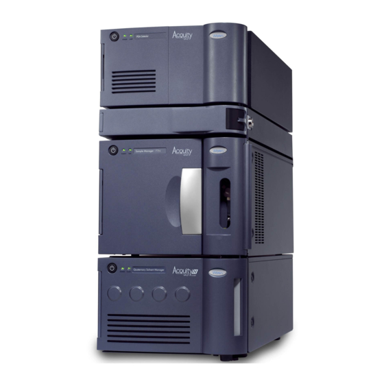
Page 17: System Components
• Auto•Blend Plus Technology for Ion Exchange, Size Exclusion, and Reversed-phase Chromatography, included on the system documentation media. • The Auto•Blend Plus videos on the Support tab on the Waters Auto•Blend Plus page. 1.3 System components The following illustration depicts a system stack which includes four core modules and the solvent bottle tray. - Page 18 The system includes a solvent manager, sample manager, column heater, detector (tunable ultraviolet, photodiode array, evaporative light scattering, fluorescent, conductivity, refractive index, or mass spectrometry), and an ACQUITY UPLC column. Waters Empower chromatography software, UNIFI, or MassLynx mass spectrometry software controls the system. April 4, 2018, 715005702 Rev. A...
-
Page 19: Quaternary Solvent Manager (Qsm)
Note: An optional degasser vent line extension exists for applications requiring longer tubing lengths. For more information, contact your local Waters distributor. 1.3.2 Sample manager-flow through needle (SM-FTN) The sample manager-flow through needle (SM-FTN) uses a direct-injection mechanism to inject samples drawn from plates and vials onto a chromatographic column. -
Page 20: Column Heater (Ch-A)
1.3.4 Column manager (optional) The ACQUITY UPLC H-Class Series column manager is an option for helping to ensure precise, reproducible separations. The column manager can regulate the temperature of columns from 4 to 90 °C. Its troughs can accommodate columns of up to 4.6-mm I.D. and up to 150-mm length, depending on the configuration. -
Page 21: Column Module Switch Box (Optional)
1.3.5 Column Module Switch Box (optional) With the optional Waters Column Module Switch Box, you can physically connect a column heater (CH-A) and a 30-cm column module (either a CH-30A or a 30-cm CHC) to the sample manager - flow-through-needle (SM-FTN) and switch the electrical control of the column modules via the SM-FTN console. -
Page 22: Flexcart (Optional)
Note: The ACQUITY FlexCart is not supported with the ACQUITY QDa detector or any ACQUITY UPLC H-Class Series system with dual detection (split-stack configurations). 1.3.8 Post-Injection Volume Kit (optional) This optional kit includes a 50-µL extension loop that provides additional post-injection mixing. -
Page 23: For Additional Information
MS-compatible flow rates, and matched outlet tubing minimizes the effect of extra-column volume. Although the system works with any analytical column, specially designed ACQUITY UPLC columns maximize its high-pressure capabilities. Compared with traditional HPLC columns, ACQUITY UPLC columns deliver superior resolution and sensitivity in the same run time or equivalent resolution, greater sensitivity, and faster run times. - Page 24 • Auto•Blend Plus Technology for Ion Exchange, Size Exclusion, and Reversed-phase Chromatography Visit Waters.com to find more information and to join the ACQUITY UPLC online community, where you can: • Share information with and ask questions of ACQUITY UPLC experts and scientists.
-
Page 25: Performance Optimization
When performing fast UPLC analyses, a peak of interest can be less than 0.5 seconds in width. Waters recommends a sampling rate that will generate between 25 and 50 points across the narrowest integrated peak in the separation in order to ensure repeatable quantification and while maximizing sensitivity. -
Page 26: Follow These General Recommendations When Performing A Uplc Analysis
2.1.1 Follow these general recommendations when performing a UPLC analysis Select appropriate solutions • Use high-quality solvents, buffers, and additives (HPLC or MS grade). • Keep concentrated stock solutions, to use when preparing working solutions. • Start gradients that include an organic component (0.1%, for example) to provide more consistent and predictable gradient formation than when you start with 0% organic. -
Page 27: Dispersion
An ACQUITY UPLC H-Class Series system typically exhibits a bandspread (5σ) of ≤12 µL, depending on system configuration. A typical HPLC system can exhibit a bandspread between 35 µL and 50 µL. -
Page 28: Cycle Time (Between Injections)
A common cause of carryover is inadequate washing of the system. Choosing an appropriate wash solvent can minimize carryover for a particular analysis. The wash solvent must be strong enough to dissolve any remaining sample, and the wash duration must be long enough to remove the residue from the system. -
Page 29: Installation Recommendations For Fittings
(downstream of the "intelligent" intake valves) can leak solvent but do not introduce air. To prevent leaks, follow Waters’ recommendations for the proper tightening of system fittings. Note that different techniques apply to re-tightening fittings versus installing them for the first time. - Page 30 Warning: To avoid eye injury, use eye protection when performing this procedure. Notice: To prevent contaminating system components, wear clean, chemical-resistant, powder-free gloves when performing this procedure. Required tools and materials • Chemical-resistant, powder-free gloves • Protective eyewear • 1/2-inch open-end wrench •...
- Page 31 2.5.1.2 Stainless steel (gold-plated) fitting with long flats and 2-piece stainless steel ferrule (V-detail) First use Long flats Compression screw 2-piece stainless steel ferrule Tighten the fitting finger-tight plus an additional 3/4-turn using a 1/4-inch open-end wrench. For detailed instructions about assembling new fittings, see Assembling new fittings.
- Page 32 Long flats Compression screw 2-piece stainless steel ferrule Tighten the fitting finger-tight plus as much as an additional 1/6-turn using a 1/4-inch open-end wrench. Reinstalled tightening 2.5.1.3 Stainless steel (gold-plated) fitting with short flats and 2-piece stainless steel ferrule (V-detail) First use Short flats Compression screw...
- Page 33 First use tightening Reinstalled Short flats Compression screw 2-piece stainless steel ferrule Tighten the fitting finger-tight plus as much as an additional 1/6-turn using a 1/4-inch open-end wrench. Reinstalled tightening April 4, 2018, 715005702 Rev. A Page 33...
- Page 34 2.5.1.4 1/4-28 flangeless fitting with ferrule First use or re-installed Compression screw Ferrule Tighten the fitting finger-tight. 2.5.1.5 1/4-28 flangeless fitting with 2-piece ferrule First use or re-installed Compression screw 2-piece ferrule Tighten the fitting finger-tight. April 4, 2018, 715005702 Rev. A Page 34...
- Page 35 2.5.1.6 Long 1/4-28 fitting with flangeless ferrule and stainless steel lock ring installed on 1/8-inch OD tubing First use or re-installed Compression screw Lock ring Ferrule End of lock ring with larger inside diameter (ID) Tighten the fitting finger-tight. 2.5.1.7 Short 1/4-28 fitting with flangeless ferrule and stainless steel lock ring installed on 1/16-inch OD tubing First use or re-installed Compression screw...
- Page 36 Tighten the fitting finger-tight. 2.5.1.8 5/16-24 fitting with filter and stainless steel lock ring First use or re-installed Compression screw Lock ring Ferrule and filter End of lock ring with larger inside diameter (ID) Tighten the fitting finger-tight. 2.5.1.9 PEEK fitting with PEEK ferrule and stainless steel lock ring First use or re-installed Compression screw Lock ring...
- Page 37 2.5.1.10 One-piece PEEK fitting Figure 2–1: First use or reinstalled Compression screw Tighten the fitting finger-tight. Tips: • You can also use the column gripping tool when tightening this fitting. • To prevent band spreading, ensure that the tubing is fully bottomed in the connection port before tightening the fitting.
- Page 38 Figure 2–3: Column-stabilizer outlet fitting first use or reinstalled #1 hex compression fitting #2 locking cap nut Back-locking PEEK ferrule Figure 2–4: Legacy fitting first use or reinstalled Hex compression fitting Locking cap nut Back-locking or standard PEEK ferrule To tighten the fitting: Loosen the cap nut from the compression fitting.
- Page 39 While holding the column with the column gripping tool, tighten the column onto the compression fitting. Figure 2–5: Tightening the column onto the compression fitting Compression fitting Column gripping tool Column Tip: If you are operating the system at, or close to, its maximum system operating pressure limit and the fitting is a hex, use the 1/2-inch open-end wrench to tighten the compression fitting an additional 1/8- to 1/6-turn.
- Page 40 Required tools and materials • Chemical-resistant, powder-free gloves • Protective eyewear • Replacement ferrule To replace the ferrule on the column fitting: Unscrew the #2 locking cap nut from the #1 knurled compression fitting. Figure 2–6: Unscrewing cap nut from fitting #1 knurled compression fitting #2 locking cap nut Slide the #1 knurled compression fitting off the tubing.
- Page 41 Figure 2–8: Removing ferrule from fitting #1 knurled compression fitting Ferrule (captive ferrule shown) Discard the used ferrule. Install the new ferrule on the fitting. Slide the #1 knurled compression fitting and ferrule onto the tubing. Figure 2–9: Sliding fitting and ferrule onto tubing Tubing #1 knurled compression fitting Note:...
-
Page 42: Developing Methods
2.7 Sample preparation 2.7.1 Particulates Waters recommends filtering all samples with particulates through a 0.2 µm sample filter or installing a column pre-filter. The small column frit size (0.2 µm) can become blocked more easily than larger HPLC column frits (2.0 µm). As a result, particle-free mobile phase solvents and sample solutions are essential for UPLC analysis. -
Page 43: Transferring Methods
The ACQUITY UPLC H-Class Series system, which Waters designed specifically to facilitate method transfer, is the ideal tool to achieve that goal with quaternary solvent capability, low pressure mixing, and flow through needle design. The optional column manager facilitates switching between target columns while exhibiting low bandspread and maintaining the same temperature profile as the standard column heater. - Page 44 Using the Waters ACQUITY UPLC Columns Calculator ensures the best results for transferring the LC method from HPLC to UPLC or UPLC to HPLC.
-
Page 45: Columns Calculator
• For a target system, with a smaller volume, use an isocratic hold to account for the dwell volume differences. • Active preheating is the default configuration for the ACQUITY UPLC H-Class Series system. An optional, passive, column stabilizer is available for existing chromatographic methods not suitable for active preheating. -
Page 46: Solvent Recommendations
L/dp of the existing method column and the target column. Because the dwell volumes of the ACQUITY UPLC H-Class Series system are far smaller than those of a conventional HPLC system, often a gradient hold is required. -
Page 47: System Preparation
The following start-up tests run: CPU board, memory (RAM and ROM), external communication system (Ethernet), and clock. If the start-up tests indicate a malfunction, contact your local Waters representative. Power-on the sample manager and then the solvent manager, by pressing the power switch on the top, left-hand side of each device's door. -
Page 48: Opening The Console
Requirement: If this is the first time you are using this system, you must define a new system. For instructions, see the online Help. Open the control panels and console. See also: Monitoring control panels Opening the console Prime the system. See also: Priming the system 3.2 Opening the console... -
Page 49: To Open The Console From Unifi Software
3.2.3 To open the console from UNIFI software From the UNIFI Portal, click the My Work tab. From the My Work tab, select Instrument Systems, and then double-click on the device that you want to monitor. Alternative: Launch the System Console from the System Control Panel menu. Result: A control panel for the selected device appears. - Page 50 Alternative: Firmware upload is in progress. Steady red A failure is preventing operation. Cycle power to the sample manager. If the LED remains red, report the problem to Waters Technical Support. Alternative: Firmware upload is complete. 3.4.2.2 Flow LED Flow status is indicated by an LED on the solvent manager’s front panel. The flow LED is on the right-hand side of the power LED.
-
Page 51: Enabling The Leak Sensors
An error stopped the detector's operation. Refer to the console log for information about the error. Steady red A failure is preventing the detector from operating. If, after you cycle power to the detector, the LED remains red, report the problem to Waters Technical Service. 3.5 Enabling the leak sensors Rule: When you power-on the system, the leak sensors default to disabled status unless previously enabled. -
Page 52: Monitoring From Control Panels
To enable the leak sensors: In the ACQUITY UPLC Console, select Control > Leak Sensors. To enable the leak sensor for an individual module, click the status on the left-hand side of the module’s description. Tip: To enable all leak sensors, click Enable All. 3.6 Monitoring from control panels You can monitor the sample manager, solvent manager, column module, detector, and fraction manager from control panels, which you access via the chromatography data system. -
Page 53: Sample Manager Control Panel
Figure 3–1: Column manager control panel The following table describes the items in the column manager's control panel: Run LED - Mirrors the run status LED on the column manager's front panel, unless communications are interrupted. Column currently in use - Displays the column that is currently in use. Current temperature - Displays the current column compartment temperature. - Page 54 Figure 3–2: SM-FTN control panel Run LED – Mirrors the run status LED on the sample manager's front panel, unless communications are interrupted. Current column compartment temperature – Displays the current temperature of the sample compartment. Display console – When clicked, launches the console software. Column compartment temperature set point –...
-
Page 55: Quaternary Solvent Manager Control Panel
3.6.3 Quaternary solvent manager control panel The control panel of the quaternary solvent manager (QSM) displays system pressure, total flow rate, and solvent composition. You can edit these parameters when the system is idle by clicking the underlined value. You cannot edit solvent manager parameters while the system is running samples. -
Page 56: Ism Control Panel
Table 3–6: Additional functions in the QSM control panel Control panel Description function Start up system Brings the system to operational conditions after an extended idle period or when switching to different solvents. See also: Console online Help Prime solvents Displays the Prime Solvent dialog box and allows for manual changeover or refreshing of solvent. - Page 57 Figure 3–4: ISM control panel Flow LED – Displays on the front panel of the solvent manager the status of the flow state, unless communications are lost. Flow rate – Displays the flow rate of solvent through all lines of the ISM, from 0.000 to 2.000 mL/min, under normal operation, and 0.000 to 4.000 mL/min, when priming.
-
Page 58: Els Control Panel
Table 3–7: Additional functions in the ISM control panel (continued) Control panel Description function Wash plungers Initiates the plunger-wash sequence, which fills and then slowly empties the primary and accumulator chambers (with the current solvent composition) while performing a high speed/volume seal wash. This action helps prevent precipitate buildup on the pump plungers. -
Page 59: Flr Control Panel
Lamp icon – When clicked, ignites or extinguishes the lamp. If the icon is green, the lamp is ignited. If the icon is red, the lamp is extinguished. Current nebulizer gas pressure – Displays the current nebulizer set gas pressure from 20 to 60 psi. -
Page 60: Pda Control Panel
Lamp LED – Mirrors the lamp status LED on the front panel of the detector, unless communications with the detector are lost. Emission units or energy units – Displays the emission units or energy units. Lamp icon – When clicked, ignites or extinguishes the lamp. If the icon is green, the lamp is ignited. -
Page 61: Ri Control Panel
Figure 3–7: PDA detector control panel Lamp LED – Mirrors the lamp status LED on the front panel of the detector, unless communications with the detector are interrupted. Lamp icon – When clicked, ignites or extinguishes the lamp. If the icon is green, the lamp is ignited. -
Page 62: Tuv Control Panel
Figure 3–8: RI detector control panel Run status LED – Mirrors the run status LED on the front panel of the detector, unless communications with the detector are interrupted. Recycle indicator – When clicked, the recycle valve changes positions to avoid wasting solvent when equilibrating the detector. -
Page 63: Acquity Qda
You can edit detector parameters when the system is idle by clicking the underlined value. You cannot edit these values while the system is running samples. Figure 3–9: TUV detector control panel The following table describes the items in the TUV’s control panel: Lamp LED –... -
Page 64: 2432 Conductivity Control Panel
• Selected ion recording (SIR), where the instrument records the signal intensity at a static m/z ratio. For more information, see the ACQUITY QDa Detector Overview and Maintenance Guide on your documentation media, or at Waters.com. 3.6.11 2432 conductivity control panel The 2432 conductivity detector's control panel displays the conductivity, peak polarity, and the cell temperature. - Page 65 Notice: • Do not leave buffers stored in the system. • Flush all flow paths, including the needle wash, with plenty of non-buffered solvent before shutting down the system. • For extended shutdown periods (longer than 24 hours), use 10% to 20% methanol in water.
- Page 66 On the Equilibrate to Method tab, click each module sub-tab and if necessary, change the settings for the flow rate, solvent composition, temperature, and lamp state to match your requirements at equilibration. Table 3–14: Equilibrate to Method table values System startup Default Allowed values parameters...
-
Page 67: System Maintenance
4.1 Contacting Waters Technical Service If you are located in the USA or Canada, report malfunctions or other problems to Waters Technical Service (800-252-4752). From elsewhere, phone the Waters corporate headquarters in Milford, Massachusetts (USA), or contact your local Waters subsidiary. The Waters website includes phone numbers and email addresses for Waters locations worldwide. -
Page 68: Maintenance Procedures And Frequency
Consult the individual module's overview and maintenance guide on the documentation media for routine maintenance procedures and frequency. 4.3 Spare parts To ensure that your system operates as designed, use only Waters Quality Parts. Visit www.waters.com/wqp for information about Waters Quality Parts, including how to order them. -
Page 69: External Connections
Installation recommendations for fittings. Note: A Waters Technical Service representative unpacks and installs the system components. Warning: To avoid spinal and muscular injury, do not attempt to lift a system module without assistance. If you must transport a system component, or remove it from service, request recommended cleaning, flushing, and packaging procedures from Waters Technical Service. -
Page 70: External Cable Connections
5.2 External cable connections Figure 5–1: System rear-panel cable connections Detector Column heater Sample manager (SM-FTN) Solvent manager (QSM) Ethernet switch Workstation Interconnect (D-sub) cables Ethernet cables April 4, 2018, 715005702 Rev. A Page 70... -
Page 71: Plumbing Connections
5.3 Plumbing connections Figure 5–2: System plumbing connections Detector Column heater Sample manager (SM-FTN) Solvent manager (QSM) Stainless steel tubing PEEK tubing April 4, 2018, 715005702 Rev. A Page 71... -
Page 72: Waste-Tubing Connections
5.4 Waste-tubing connections Figure 5–3: System waste-tubing connections Solvent bottle tray Detector April 4, 2018, 715005702 Rev. A Page 72... -
Page 73: Electricity Source
(CH-30A), and the column manager auxiliary (CM-Aux), receive their power from the sample manager via the interconnect cable. Recommendation: Use a line conditioner and uninterruptible power supply (UPS) for optimum, long-term, input-voltage stability. Contact Waters to ensure the correct selection and size. April 4, 2018, 715005702 Rev. A Page 73... -
Page 74: Connecting To A Cart's Electricity Source
To avoid electric shock, observe these precautions: • Use SVT-type power cords in the United States and HAR-type power cords, or better, in Europe. For requirements elsewhere, contact your local Waters distributor. • Inspect the power cords for damage and replace them if necessary. - Page 75 To connect the cables: Insert the connector into the connector port on the module's rear panel. Figure 5–4: Inserting connector into connector port Connector port Connector Using the flat-blade screwdriver, attach the positive and negative leads of the signal cable to the connector.
-
Page 76: Connecting To A Column Module
Fork terminal Locking nut Grounding stud 5.7 Connecting to a column module The following column modules are compatible with the ACQUITY UPLC H-Class Series system: • Column heater (CH-A) • Column heater 30 cm (CH-30A) • Column heater/cooler (30 cm CHC) •... - Page 77 To connect the column module: Notice: To avoid damaging the electronic components of the sample manager and the column heater or column heater/cooler, always power-off the sample manager and column heater/cooler before connecting or disconnecting the interconnect cable. Ensure that the sample manager and the column module are powered-off. Connect the interconnect cable to the High Density (HD) port on the rear of the column module.
-
Page 78: A Post-Injection Volume Kit Instructions
Post-Injection Volume Kit instructions Warning: To avoid personal contamination with biologically hazardous or toxic compounds, wear clean, chemical-resistant, powder-free gloves when performing this procedure. Requirement: Wear clean, chemical-resistant, powder-free gloves when performing this procedure. Required tools and materials • Chemical-resistant, powder-free gloves •... - Page 79 Post-injection loop union Post-injection loop tubing Post-injection loop fitting Screw the active preheater (APH) fitting into the post-injection loop union, and then use the 1/4-inch open-end wrench to tighten the fitting 3/4-turn beyond finger-tight for a new fitting, or 1/6-turn beyond finger-tight for existing fittings. Close the fluidics compartment door.
-
Page 80: B Safety Advisories
Heed all warnings when you install, repair, or operate any Waters instrument or device. Waters accepts no liability in cases of injury or property damage resulting from the failure of individuals to comply with any safety precaution when installing, repairing, or operating any of its instruments or devices. -
Page 81: Specific Warnings
(Risk of high-pressure gas release.) B.1.1 Specific warnings B.1.1.1 Burst warning This warning applies to Waters instruments and devices fitted with nonmetallic tubing. Warning: To avoid injury from bursting, nonmetallic tubing, heed these precautions when working in the vicinity of such tubing when it is pressurized: •... -
Page 82: Notices
B.1.1.2 Biohazard warning The following warning applies to Waters instruments and devices that can process biologically hazardous materials. Biologically hazardous materials are substances that contain biological agents capable of producing harmful effects in humans. Warning: To avoid infection from blood-borne pathogens, inactivated microorganisms, and other biological materials, assume that all biological fluids that you handle are infectious. -
Page 83: Bottles Prohibited Symbol
Use eye protection when performing this procedure. Requirement: Wear clean, chemical-resistant, powder-free gloves when performing this procedure. B.5 Warnings that apply to all Waters instruments and devices When operating this device, follow standard quality-control procedures and the equipment guidelines in this section. - Page 84 Advertencia: cualquier cambio o modificación efectuado en esta unidad que no haya sido expresamente aprobado por la parte responsable del cumplimiento puede anular la autorización del usuario para utilizar el equipo. 警告: 未經有關法規認證部門允許對本設備進行的改變或修改,可能會使使用者喪失操作 該設備的權利。 警告: 未经有关法规认证部门明确允许对本设备进行的改变或改装,可能会使使用者丧 失操作该设备的合法性。 경고: 규정 준수를 책임지는 당사자의 명백한 승인 없이 이 장치를 개조 또는 변경할 경우, 이...
- Page 85 Warnung: Bei der Arbeit mit Polymerschläuchen unter Druck ist besondere Vorsicht angebracht: • In der Nähe von unter Druck stehenden Polymerschläuchen stets Schutzbrille tragen. • Alle offenen Flammen in der Nähe löschen. • Keine Schläuche verwenden, die stark geknickt oder überbeansprucht sind. •...
- Page 86 圧力のかかったポリマーチューブを扱うときは、注意してください。 • 加圧されたポリマーチューブの付近では、必ず保護メガネを着用してください。 • 近くにある火を消してください。 • 著しく変形した、または折れ曲がったチューブは使用しないでください。 • 非金属チューブには、テトラヒドロフラン(THF)や高濃度の硝酸または硫酸などを流さないでくださ い。 • 塩化メチレンやジメチルスルホキシドは、非金属チューブの膨張を引き起こす場合があり、その場 合、チューブは極めて低い圧力で破裂します。 This warning applies to Waters instruments fitted with nonmetallic tubing. This warning applies to instruments operated with flammable solvents. April 4, 2018, 715005702 Rev. A Page 86...
-
Page 87: Warnings That Address The Replacement Of Fuses
Warning: The user shall be made aware that if the equipment is used in a manner not specified by the manufacturer, the protection provided by the equipment may be impaired. Avertissement : L’utilisateur doit être informé que si le matériel est utilisé d’une façon non spécifiée par le fabricant, la protection assurée par le matériel risque d’être défectueuses. - Page 88 Avertissement : pour éviter tout risque d'incendie, remplacez toujours les fusibles par d'autres du type et de la puissance indiqués sur le panneau à proximité du couvercle de la boite à fusible de l'instrument. Warnung: Zum Schutz gegen Feuer die Sicherungen nur mit Sicherungen ersetzen, deren Typ und Nennwert auf den Tafeln neben den Sicherungsabdeckungen des Geräts gedruckt sind.
-
Page 89: Electrical Symbols
警告: 為了避免火災,更換保險絲時,應使用「維護步驟」章節中「更換保險絲」所指 定之相同類型與規格的保險絲。 警告: 为了避免火灾,应更换“维护步骤”一章的“更换保险丝”一节中介绍的相同类 型和规格的保险丝。 경고: 화재의 위험을 막으려면 유지관리 절차 단원의 “퓨즈 교체” 절에 설명된 것과 동 일한 타입 및 정격의 제품으로 퓨즈를 교체하십시오. 警告: 火災予防のために、ヒューズ交換ではメンテナンス項目の「ヒューズの交換」に記載されているタ イプおよび定格のヒューズをご使用ください。 B.7 Electrical symbols The following electrical symbols and their associated statements can appear in instrument manuals and on an instrument’s front or rear panels. -
Page 90: Handling Symbols
B.8 Handling symbols The following handling symbols and their associated statements can appear on labels affixed to the packaging in which instruments, devices, and component parts are shipped. Symbol Description Keep upright! Keep dry! Fragile! Use no hooks! Upper limit of temperature Lower limit of temperature Temperature limitation B.9 Stacking system modules with interlocking features... -
Page 91: Stacking System Modules Without Interlocking Features
Warning: To avoid spinal and muscular injury, do not attempt to lift a system module without assistance. Warning: To avoid crushing your fingers beneath or between modules, use extreme care when installing a module in the system stack. Warning: To avoid injury, do not stack modules, including the solvent tray and rails, higher than one meter (39.4 inches) above the bench top. - Page 92 Warning: To avoid crushing your fingers beneath or between modules, use extreme care when installing a module in the system stack. To stack the modules: Align the front and rear feet of the module that you are adding with the corresponding indents in the top of the chassis of the previously added module in the system stack.
Need help?
Do you have a question about the ACQUITY UPLC H-Class Series and is the answer not in the manual?
Questions and answers