Table of Contents
Advertisement
Quick Links
Download this manual
See also:
Operator's Manual
Advertisement
Table of Contents
Troubleshooting

Related Manuals for Waters 717plus


Summary of Contents for Waters 717plus
- Page 1 Waters 717plus Autosampler Operator’s Manual 34 Maple Street Milford, MA 01757 173-02TP, Revision 3...
- Page 2 This manual is believed to be complete and accurate at the time of publication. In no event shall Waters Corporation be liable for incidental or consequential damages in connection with or arising from the use of this manual.
- Page 3 Note: When you use the instrument, follow generally accepted procedures for quality control and methods development. If you observe a change in the retention of a particular compound, in the resolution between two compounds, or in peak shape, immediately determine the reason for the changes.
- Page 4 Caution: Use caution when working with any polymer tubing under pressure: • Always wear eye protection when near pressurized polymer tubing. • Extinguish all nearby flames. • Do not use Tefzel tubing that has been severely stressed or kinked. • Do not use Tefzel tubing with tetrahydrofuran (THF) or concentrated nitric or sulfuric acids.
- Page 5 Precauzione: prestare attenzione durante le operazioni con i tubi di polimero sotto pressione: • Indossare sempre occhiali da lavoro protettivi nei pressi di tubi di polimero pressurizzati. • Estinguere ogni fonte di ignizione circostante. • Non utilizzare tubi Tefzel soggetti a sollecitazioni eccessive o incurvati. •...
- Page 7 Caution: The user shall be made aware that if the equipment is used in a manner not specified by the manufacturer, the protection provided by the equipment may be impaired. Attention : L’utilisateur doit être informé que si le matériel est utilisé d’une façon non spécifiée par le fabricant, la protection assurée par le matériel risque d’être défectueuses.
- Page 8 Caution: To protect against fire hazard, replace fuses with those of the same type and rating. Attention : Remplacez toujours les fusibles par d’autres du même type et de la même puissance afin d’éviter tout risque d’incendie. Vorsicht: Zum Schutz gegen Feuergefahr die Sicherungen nur mit Sicherungen des gleichen Typs und Nennwertes ersetzen.
- Page 9 Caution: To avoid possible electrical shock, power off the instrument and disconnect the power cord before servicing the instrument. Attention : Afin d’éviter toute possibilité de commotion électrique, mettez hors tension l’instrument et débranchez le cordon d’alimentation de la prise avant d’effectuer la maintenance de l’instrument.
- Page 10 Commonly Used Symbols Direct current Courant continu Gleichstrom Corrente continua Corriente continua Alternating current Courant alternatif Wechselstrom Corrente alternata Corriente alterna Protective conductor terminal Borne du conducteur de protection Schutzleiteranschluss Terminale di conduttore con protezione Borne del conductor de tierra...
- Page 11 Commonly Used Symbols (Continued) Frame or chassis terminal Borne du cadre ou du châssis Rahmen- oder Chassisanschluss Terminale di struttura o telaio Borne de la estructura o del chasis Caution or refer to manual Attention ou reportez-vous au guide Vorsicht, oder lesen Sie das Handbuch Prestare attenzione o fare riferimento alla guida Actúe con precaución o consulte la guía Caution, hot surface or high temperature...
- Page 12 Commonly Used Symbols (Continued) Caution, risk of electric shock (high voltage) Attention, risque de commotion électrique (haute tension) Vorsicht, Elektroschockgefahr (Hochspannung) Precauzione, rischio di scossa elettrica (alta tensione) Precaución, peligro de descarga eléctrica (alta tensión) Caution, risk of needle-stick puncture Attention, risques de perforation de la taille d’une aiguille Vorsicht, Gefahr einer Spritzenpunktierung Precauzione, rischio di puntura con ago...
- Page 13 717plus Autosampler Information Intended Use The Waters 717plus Autosampler can be used for in-vitro diagnostic testing to analyze many compounds, including diagnostic indicators and therapeutically monitored compounds. When you develop methods, follow the “Protocol for the Adoption of Analytical Methods in the Clinical Chemistry Laboratory,” American Journal of Medical Technology, 44, 1, pages 30–37 (1978).
-
Page 14: Table Of Contents
2.5.2 Making IEEE-488 Network Connections....45 2.5.3 Connecting RS-232 Output to Data Module ....46 2.6 Changing the Hardware Configuration........47 2.6.1 Removing/Replacing the 717plus Cover....47 2.6.2 Installing the Heater/Cooler ........49 2.6.3 Installing the Large Sample Loop ......52... - Page 15 Chapter 3 Startup and Configuration ..............55 3.1 Powering Up the Autosampler..........55 3.2 Using the Front Panel............56 3.2.1 Accessing Menus............57 3.2.2 Entering Operating Parameters ......... 58 3.3 Flushing the Autosampler ............. 59 3.4 Calibrating the Seal Pak............59 3.4.1 Purging the Autosampler ...........
- Page 16 4.2.2 Selecting Sample Vials ..........81 4.3 Selecting a Needle Wash Solvent ......... 82 4.4 Loading the Carousel............84 4.5 Ensuring Reproducibility ............86 4.5.1 Overview of Reproducibility ........86 4.5.2 Performing a Purge............ 87 4.5.3 Performing a Compression Check ......89 4.6 Running Autosampling ............
- Page 17 Chapter 5 Maintenance .................. 127 5.1 Defrosting the Heater/Cooler ..........127 5.2 Replacing the Syringe............129 5.2.1 Removing the Syringe ..........129 5.2.2 Installing the New Syringe ........132 5.3 Replacing the Seal Pak............135 5.3.1 Removing the Injector..........136 5.3.2 Removing the Seal Pak ...........
- Page 18 6.4 Troubleshooting Procedures ..........154 6.4.1 Manual Syringe Purge ..........154 6.4.2 Valve Leak Test ............155 6.4.3 Manual Transducer Adjustment ....... 158 Appendix A Specifications ................. 161 Appendix B Spare Parts..................164 Appendix C Reproducibility and Solvent Degassing .......... 167 C.1 Factors Affecting Reproducibility ........
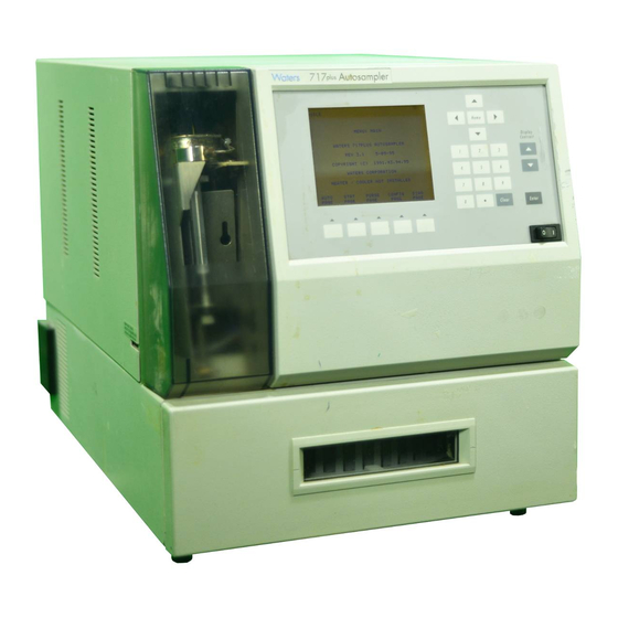
- Page 19 List of Figures Waters 717plus Autosampler............27 Waters 717plus Autosampler Subsystems ........32 Waters 717plus Autosampler Site Requirements ......34 Fluid Line Connections ..............37 Drain Line Connections ..............38 Autosampler Rear Panel..............39 Terminal Strip................. 42 IEEE-488 Connections ..............46 Removing the Autosampler Cover ..........
- Page 20 Overview of Operations ..............78 Preparing Samples ................ 80 Sample Vial Assembly ..............82 Improper Needle Wash Solvent Location ........84 Inserting the Carousel ..............85 Purging the Autosampler ............... 87 Purge and Compressibility Page ........... 88 Running a Compressibility Test ............. 90 Overview of Programming .............
- Page 21 Defrost Menu Flowchart .............. 128 Syringe Assembly Components........... 130 Positioning the Syringe for Removal ..........131 Installing the Syringe ..............133 Changing Syringe Volume ............134 Removing the Injector (shown with Safety Shield Removed) ..137 Bottom View of Injector..............138 Needle Removal ................
- Page 22 List of Tables Terminal Strip Signals ..............40 System Controller Connections ..........43 Auto Zero Connections............44 Chart Mark Connections ............44 RS-232 Parameters..............47 Menu Functions ................57 Configuration Parameters............67 Hold Logic................70 Suggested Needle Wash Solvents ..........83 Autosampler Volume ...............
- Page 23 Spare Parts ................. 164 Sample Vials for 48-Vial Carousel ..........173 Sample Vials for 96-Vial Carousel ..........174 List of Tables...
-
Page 24: Preface
Preface The Waters 717plus Autosampler Operator’s Manual describes the features and use of ® the Waters 717plus Autosampler. It also includes installation, maintenance, and troubleshooting procedures. The audience for this operator’s manual includes chemists and technicians who will use the autosampler to make injections for chromatographic analysis. - Page 25 Adobe Acrobat Reader lets you easily print pages, page ranges, or the entire document by selecting File > Print. For optimum print quantity, Waters recommends that you specify a ® PostScript printer driver for your printer. Ideally, use a printer that supports 600 dpi print resolution.
- Page 26 Convention Usage (Continued) A right arrow between menu options indicates you should choose > each option in sequence. For example, “Select File > Exit” means you should select File from the menu bar, then select Exit from the File menu. Notes Notes call out information that is helpful to the operator.
-
Page 27: Chapter 1 Introduction
(Figure 1-1) may be used as either a stand-alone unit or as a component in a Waters IEEE-488 based HPLC system. As part of an IEEE-488 based system, the autosampler may be controlled by Waters PowerLine™ System Controllers or Waters Data Workstations. -
Page 28: Features
• Auto Standards – Allows you to run standards automatically during a run. • Auto Transfer – Allows you to program the 717plus Autosampler to transfer solutions from specified vials to your sample vial; to mix the solution; and to inject. - Page 29 Interaction with Other LC Modules The Waters 717plus Autosampler sends and receives signals from other LC modules, including: • Inject Start – Occurs when the sample is injected into the mobile phase stream. Initiates data acquisition, fraction collection, and detector autozero. Contact closure is initiated by the autosampler.
- Page 30 • Extends seal life by removing the mobile phase and the sample from the sampling needle Semiprep Chromatography For semiprep chromatography (up to 2 mL injections), the 717plus Autosampler may be configured with optional: • 2000-µL sample loop – Required for injections greater than 200 µL •...
-
Page 31: Components And Subsystems
1.3 Components and Subsystems This section describes the components and subsystems of the Waters 717plus Autosampler (Figure 1-2): • Front Panel – Contains a display screen, keypad, and function keys, and provides access to the control system. • Autosampler Controller – Contains a microprocessor and memory for controlling all autosampler components. -
Page 32: Waters 717Plus Autosampler Subsystems
(stepper motor) Syringe Empty Injector Top and Full Position (and Bottom Sensors Sensors Sample Loop Valve(v1) Inlet Line from Pump (blue) Outlet Line to Column (red) T P 0 1 9 4 1 Figure 1-2 Waters 717plus Autosampler Subsystems Introduction... -
Page 33: Chapter 2 Installation
Chapter 2 Installation This chapter describes 717plus Autosampler installation and setup. It includes procedures for making connections, voltage selection, and configuring optional hardware. 2.1 Site Requirements Required Space Before beginning the installation procedure, note the following autosampler site and utility... -
Page 34: Waters 717Plus Autosampler Site Requirements
Note that cooler performance is derated above 27 °C Humidity 80% maximum relative humidity, noncondensing Do not locate the Waters 717plus Autosampler in direct sunlight, near heat registers, or under air conditioning vents. Weight Requires a bench capable of supporting at least 75 pounds. -
Page 35: Unpacking And Inspection
5. Grasp the autosampler from the bottom to lift. Do not lift by holding the front panel. 6. Place the 717plus Autosampler securely on the bench top. Allow clearance for the power cord and ventilation. -
Page 36: Making The Power Supply Connection
2.3 Making the Power Supply Connection The Waters 717plus Autosampler adjusts for ac input voltages of 100 to 240 Vac at 50/60 Hz. To make the power supply connection: 1. Check that the Power On/Off switch is in the Off position. -
Page 37: Fluid Line Connections
Connecting Fluid Lines To connect the fluid lines (Figure 2-2): Red Line to Column Green Line to Needle Wash Solvent Home CAROUSEL Engage Release Clear Enter Blue Line to Pump Yellow and Clear Lines to Waste Figure 2-2 Fluid Line Connections 1. -
Page 38: Drain Line Connections
Installing Drain Lines Using parts from the 717plus Autosampler Startup Kit, connect the two drain lines to the drain pans located on the bottom of the autosampler (Figure 2-3) as follows: 1. Place an appropriate waste container for solvent and sample leaks below bench level. -
Page 39: Connecting Communication Cables
LC components. • IEEE-488 – Communicates with a system controller over the IEEE network. • RS-232 – Provides information to RS-232 based data systems such as the Waters 746 Data Integrator. This section describes the communication connections listed above. -
Page 40: Making Terminal Strip Connections
Output signals the end of the programmed run time 3, 8, 13 Ground Signal ground for cable shields For specific information on signal use with other Waters equipment, refer to the appropriate manual. Electrical Specifications Input (Hold) terminal specifications are: • TTL or switch closure •... - Page 41 In addition, ensure you always connect the shield of the cable to chassis ground at one instrument only. Making Cable Connections Tools required: • One small-blade screwdriver • One electrical insulation stripping tool • Signal cable from 717plus Autosampler Startup Kit Connecting Communication Cables...
-
Page 42: Terminal Strip
Note: Some system controllers do not allow injections of less than 1 µL. To make injections of less than 1 µL, do not operate the Waters 717plus Autosampler over the IEEE bus. System Controller Connections Using a signal (contact closure) from the Waters 717plus Autosampler, a Waters system controller can coordinate the start of detectors, pumps, and computers. - Page 43 Maxima™ Watch Dog Event Box IN 1 or IN 2 Making LAC/E Connections Use the Inject Start signal from the Waters 717plus: • If the LAC/E™ system contains components such as detectors that are not connected to the IEEE-488 bus.
-
Page 44: Auto Zero Connections
Auto Zero detectors Detector Data Transfer and Chart Marking Using the Inject Start signal from the Waters 717plus autosampler, a Waters detector can: • Start data transfer over the IEEE-488 bus when the autosampler initiates an injection Note: If you specify start by LAC/E, you do not need the Inject Start signal. -
Page 45: Making Ieee-488 Network Connections
Power down all instruments on the IEEE-488 bus before making connections. STOP 1. Connect one end of the IEEE-488 cable to the IEEE connector of the 717plus Autosampler. 2. Connect the other end of the IEEE-488 cable to a system controller or to any one of your IEEE-488 components. -
Page 46: Connecting Rs-232 Output To Data Module
2.5.3 Connecting RS-232 Output to Data Module The RS-232 connector on the rear panel allows the autosampler to transfer injection parameters to a data integrator such as the Waters 746 Data Integrator. You may use the RS-232 port with any device that can read ASCII code. -
Page 47: Changing The Hardware Configuration
3. Slide back the cover until it clears the posts on the rear panel. 4. Ensure that the red and blue fluid lines are free of the side cover slots. 5. Lift the cover up and back. Attention: Always replace the 717plus Autosampler cover to maintain RFI and EMI STOP shielding integrity. Caution: To avoid the possibility of electric shock, do not remove the power supply cover. -
Page 48: Removing The Autosampler Cover
1. Lift up syringe cover to remove. Front Flanges 2. Remove cover Side Slots retaining (for Fluid Lines) screw. Side Flanges 3. Pull cover back to clear posts, fluid lines, and I N J E C T S T O P P R O G E V E N T front I N J E C T S TA R T... -
Page 49: Installing The Heater/Cooler
• Install the temperature probe To install the heater/cooler: 1. Disconnect the power cord and remove the autosampler cover (see Section 2.6.1, Removing/Replacing the 717plus Cover). 2. Remove the rear chamber assembly by unlatching the side clips, and pulling the assembly back. -
Page 50: Installing Heater/Cooler
Side Clips Heater/Cooler Power Cable T P 0 1 9 8 9 Figure 2-8 Installing Heater/Cooler 5. Feed the power cable up through the opening in the chassis and attach it to the J20 connector on the main circuit board (Figure 2-9). -
Page 51: Connecting The Heater/Cooler Power Cord And Temperature Probe
Heater/Cooler Temperature Probe Power Connector Connector (J20) Opening For Heater/Cooler Power Cable Figure 2-9 Connecting the Heater/Cooler Power Cord and Temperature Probe 6. Push the temperature probe through the grommet located on the floor of the unit behind the carousel drive (Figure 2-10). -
Page 52: Installing The Large Sample Loop
Figure 2-9). 8. Replace the autosampler cover (see Section 2.6.1, Removing/Replacing the 717plus Cover) and reconnect the power cord. 2.6.3 Installing the Large Sample Loop To inject sample volumes greater than 200 µL, you must install the auxiliary loop. Caution: To avoid the possibility of electric shock, disconnect the autosampler power cord before continuing this procedure. -
Page 53: Disconnecting The Sample Loop
• Auxiliary loop from 717plus Autosampler Startup Kit • Union from 717plus Autosampler Startup Kit To install the loop: 1. From the 717plus front panel, set system flow to 0 mL/min. 2. Turn off the autosampler, disconnect the power cord, and remove the autosampler cover (see Section 2.6.1, Removing/Replacing the 717plus... - Page 54 If the auxiliary loop was added to a previously configured autosampler, perform the procedures in: • Section 3.3, Flushing the Autosampler • Section 3.7, System Verification • Section 4.5.2, Performing a Purge Installation...
-
Page 55: Startup And Configuration
Waters 717plus Autosampler. 3.1 Powering Up the Autosampler Note: If the 717plus Autosampler is part of an IEEE-488 system, power up the 717plus Autosampler before powering up the system controller. Powerup To power up the 717plus Autosampler: 1. -
Page 56: Using The Front Panel
3-3) until the screen text is in focus. 3.2 Using the Front Panel Use the front panel (Figure 3-3) to configure the 717plus system and perform injection programming. This section describes: • Accessing menus using menu function keys • Entering operating parameters using the keypad... -
Page 57: Accessing Menus
Arrow Keys Carousel (Cursor Control) Release/Engage INIT Homing syringe Home Menu: Main Wa t e r s 7 1 7 p l u s A u t o s a m p l e r R e v 2 . 0 2 / 1 / 9 3 C o p y r i g h t ( C ) 1 9 9 1 , 9 3 CAROUSEL... -
Page 58: Entering Operating Parameters
Diagnostic: Injector Calibration Menu: Calibration Diagnostic: Auto Zero Diagnostic: Valve & Motor Operations Figure 3-4 717plus Autosampler Menu Flowchart 3.2.2 Entering Operating Parameters To enter operating parameters: 1. Access the appropriate menu by pressing the screen function key. 2. Use the arrow keys (Figure 3-2) to highlight the parameter you want to change. -
Page 59: Flushing The Autosampler
3.3 Flushing the Autosampler Solvent Considerations When flushing or purging your 717plus Autosampler, make sure the solvent is properly degassed and miscible with the previous mobile phase in the autosampler. Flushing To flush the 717plus Autosampler: 1. Place the red line in a waste container to catch the solvent. -
Page 60: Auto Zeroing The Transducer
6. If the purging fails to remove bubbles from the syringe, perform a manual purge (Section 6.4.1, Manual Syringe Purge). 3.4.2 Auto Zeroing the Transducer Auto zeroing the transducer ensures that pressure readings are accurate. To zero the transducer: 1. Ensure that the system pressure is at 0 psi. 2. -
Page 61: Path To Auto Zero Pressure Page
Menu Page Diag Page Menu: Diagnostic UserMaint Page Menu: User Maintenance Page Menu: Calibration AutoZero Page D I A G D i a g n o s t i c : A u t o Z e r o P r e s s u r e A m b i e n t p r e s s u r e w i t h n o c o r r e c t i o n m u s t b e b e t w e e n –... -
Page 62: Calibrating The Seal Pak
To attain sufficient backpressure without a column, it may be necessary to partially cap the red line with the union and fitting plug assembly included in the 717plus Startup Kit. 2. To access and run the seal pak calibration, press the keys indicated in the next... -
Page 63: Path To Seal Pak Calibration Page
Menu Page Diag Page Menu: Diagnostic UserMaint Page Menu: User Maintenance Page Menu: Calibration Page D I A G D i a g n o s t i c : I n j e c t o r C a l i b r a t i o n S e t s y s t e m p r e s s u r e t o 4 0 0 t o 6 0 0 p s i . -
Page 64: Priming The Needle Wash Pump
3.5 Priming the Needle Wash Pump To prime the needle wash pump: 1. Ensure that the needle wash supply line (green) is in the solvent bottle and the waste line (yellow) is in an appropriate container. 2. To prime the needle wash, press the keys outlined in the flowchart below (Figure 3-7). -
Page 65: Configuring The Autosampler
3.6 Configuring the Autosampler Configuring the Waters 717plus Autosampler requires: • Setting parameters to enable the autosampler to communicate with other modules in the LC system • Recording changes to autosampler hardware (syringe size and sample loop volume) 3.6.1 Overview of Configuration... -
Page 66: Autosampler Configuration Flowchart
Configure Autosampler Attach Cable Connect to (Section 2.5.3) and Set IEEE-488 System IEEE-488 Address Controller? (Section 3.6.2) Attach RS-232 Cable Connect to Data (Section 2.5). Enter Delay Integrator or Required to Set Up Data Workstation? Files (Section 3.6.2). Connect Cables to HOLD Allow Other Terminals (Section... -
Page 67: Configuration Parameters
Table 3-2 Configuration Parameters Configuration Parameter Description Page Purge In Idle? Enables purging every 60 minutes while the 717plus Autosampler is idle. See Section 4.8.5, Using Buff- ered Mobile Phase. Vials Between Purges Enables automatic purging during an auto run. See Section 4.8.4, Purging During an Auto... -
Page 68: Setting Parameters For Lc System Operation
The Report Delay provides time for the data integrator to process data from a run before a new injection begins. If a data integrator is attached to the LC system, set the delay as follows: 1. From the 717plus Main Menu, press Config Page. 2. On Configuration Page 1 (Figure 3-9), highlight the Report Delay field and enter the delay time in minutes. -
Page 69: Setting The Integrator Report Delay
I D L E E d i t : C o n f i g u r a t i o n P a g e 1 o f 4 U s e D o o r S e n s o r ? Ye s P u r g e I n I d l e ? Ye s... -
Page 70: Setting Terminal Signal Parameters
I D L E E d i t : C o n f i g u r a t i o n P a g e 2 o f 4 H o l d C o n t a c t S e n s e ? –... - Page 71 2 to 29. The default IEEE-488 address is set to 30. Note: To use the Waters 717plus Autosampler in an IEEE-488 network, you must change the address. To change the address: 1.
-
Page 72: Entering Hardware Changes
I D L E E d i t : C o n f i g u r a t i o n P a g e 4 o f 4 I E E E A d d r e s s A s s i g n m e n t Ye s Ye s I n s t a l l e d I E E E A d d r e s s :... -
Page 73: Configuration Page 3
P a g e P a g e Figure 3-12 Configuration Page 3 Entering Syringe Size To record a change in the syringe size: 1. From the 717plus Main Menu, press Config Page. 2. Press Next Page twice to access Configuration Page 3. -
Page 74: System Verification
1. Using a degassed solution of 100 percent methanol, set the solvent delivery pump to 1 mL/min. Note: For daily verification, use the mobile phase that you normally run. 2. From the 717plus Main Menu, press Edit Purge (Figure 3-13). -
Page 75: Power Down And Storage
5. Purge the autosampler. 3.8.2 Powering Down This section covers procedures for powering down the Waters 717plus Autosampler for 1 to 14 days. 1. If the current mobile phase is water, replace the water with a solution of 90 percent methanol and 10 percent water. -
Page 76: Storage
3.8.3 Storage This section covers procedures for long-term storage of the Waters 717plus Autosampler. If the autosampler will be stored for more than two weeks: 1. Remove buffered mobile phases (see Section 3.8.1, Removing Buffered Mobile Phase). 2. Power down the autosampler (see Section 3.8.2, Powering... -
Page 77: Operating The Autosampler
4.1 Overview of Operation Figure 4-1 provides an overview of autosampling. Note: If the Waters 717plus Autosampler is part of an IEEE-488 network, power up the autosampler before powering up the system controller. Overview of Operation... -
Page 78: Overview Of Operations
Operating the Autosampler Power Up Autosampler, Detectors, and Other LC Components Before System Controller Prepare Samples and Load Carousel Select Needle Wash Based on Sample and Mobile Chemistry Flush System. Perform Changing Mobile Purge and Compression Phase? Check. Purge Autosampler Program Auto Run Equilibrate Start Auto Run... -
Page 79: Preparing Samples
4.2 Preparing Samples To prepare and load samples into the autosampler, you must: • Prepare the sample • Select and fill a sample vial 4.2.1 Preparing Samples Minimum sample preparation consists of dissolving the sample: • In a solvent that is compatible with the mobile phase and column chemistry •... -
Page 80: Preparing Samples
Preparing Samples (Section 4.2.1) Normal Phase Dissolve in Mobile Phase Column? Same or Weaker Organic Reverse Phase Component as Mobile Column? Phase Use a Low Salt Ion Exchange? Concentration Dissolve in Mobile Phase GPC? (from the Same Bottle) Filter Samples with 0.5µ... -
Page 81: Selecting Sample Vials
4.2.2 Selecting Sample Vials The Waters 717plus Autosampler is compatible with the complete line of Waters chromatography sample vials. Attention: Use only sample vials and supplies from Waters. Use of non-Waters sample STOP vials, low-volume inserts, or septa may result in damage to the needle. -
Page 82: Selecting A Needle Wash Solvent
Assembling Sample Vials Assemble the sample vials as shown in Figure 4-3. Attention: Do not overtighten the cap with a self-sealing septum. Overtightening STOP (septum dimples in) may cause the cap to fit incorrectly. Also, the use of self-sealing septa may cause variable injector volumes on multiple injections due to vacuum buildup. Limited Volume Insert Screw Cap... -
Page 83: Suggested Needle Wash Solvents
Table 4-1 Suggested Needle Wash Solvents Mobile Phase Needle Wash Buffered aqueous, reverse 50% H O 50% MeOH phase Non aqueous, reverse phase 100% MeOH Normal phase Mobile phase Mobile phase Ion exchange Paired ion reagent in H To use a needle wash: 1. -
Page 84: Loading The Carousel
Clear Enter Needle Wash Pump Location Figure 4-4 Improper Needle Wash Solvent Location 3. With the 717plus Autosampler powered on, prime the needle wash pump (see Section 3.5, Priming the Needle Wash Pump). 4.4 Loading the Carousel Attention: Use only Waters grey carousels. The Waters 717plus Autosampler does not STOP work with WISP™... -
Page 85: Inserting The Carousel
3. Place the assembled sample vials in the carousel and note the location. The vial number is located on the rim of the carousel. Attention: Use of non-Waters sample vials, low-volume inserts, and septa STOP may result in damage to the needle. -
Page 86: Ensuring Reproducibility
4.5 Ensuring Reproducibility This section covers: • Overview of Reproducibility • Purging the Autosampler • Performing a Compression Check 4.5.1 Overview of Reproducibility Reproducibility depends on: • Purity of the mobile phase in the autosampler • Compressibility of the mobile phase due to dissolved gas •... -
Page 87: Performing A Purge
4.5.2 Performing a Purge Perform a purge from the Purge and Compressibility Page. Purging the Autosampler To perform a purge using the default values, press the Waters 717plus Autosampler keys as indicated below (Figure 4-6): Main Page Purge Page Purge and... -
Page 88: Purge And Compressibility Page
P U R G E E d i t : P u r g e a n d C o m p r e s s i b i l i t y P u r g e Ti m e ( m i n ) : 1 . -
Page 89: Performing A Compression Check
Table 4-3 Purge Time Examples Sample Flow Rate Purge Time Loop (mL/min) (min) Normal 12.5 >1 Auxiliary 19.4 4.5.3 Performing a Compression Check The compression check tests for gas in the mobile phase, and, when enabled, occurs immediately after a purge. For most mobile phases, use the default parameters. Note: The compression check is only valid using the standard 250-µL syringe and 200-µL sample loop. -
Page 90: Running A Compressibility Test
Pressure Decay Time Sets the length of time the system pauses before recompressing the mobile phase in the sample loop. The default value is sufficient for most applications. The longer the decay time, the more rigorous the test. Range 0.0 to 3.0 min Default 0.2 min Compressible Volume... -
Page 91: Running Autosampling
• Unattended operation – Provides injection start and stop output signals for controlling external devices. • Programmable output signal – Allows the 717plus Autosampler to control external devices during a run. • Auto Standard, Auto Addition, and Auto Transfer functions – Allow automated operation for standards, pre-injection addition of samples, and automatic pre-injection transfer and mixing. -
Page 92: Programming Auto Run
Overview of Programming Figure 4-9 is an overview of the steps involved in programming and running an auto run. Load Samples Program the Step on the Auto Run Page (Section 4.6.1) Program Step Functions for the Step (Section 4.6.2) Program the Option for the Step: Auto Standards (Section 4.6.3) -
Page 93: Edit: Auto Run Screen
4.6.1.1 Using the Auto Run Screen Display the Edit: Auto Run screen by pressing the Auto Page key on the Main Menu. The Edit: Auto Run screen (Figure 4-10) lets you program up to 96 steps. I D L E E d i t : A u t o R u n F r o m I n j... - Page 94 1. Use the arrow keys to move to a step number to delete. 2. Press Delete Options, and the Delete Line function key appears. 3. Press Delete Line. The 717plus Autosampler removes the line, and renumbers all subsequent lines. Deleting a Table To delete a table: 1. Press Delete Options, and the Delete Table function key appears.
- Page 95 Step 1. Place the cursor on a blank line, then press Enter. The 717plus Autosampler inserts a new line and copies the information, including step function and option settings, from the previous line. You can program up to 96 different steps. Each vial included in the step shares the same number of injections, injection volume, run time, step functions, and options.
-
Page 96: Programming Step Functions
Step Functions 6. Program step functions (described in Section 4.6.2, Programming Step Functions). Note: You can program only one set of step functions and one option per step. 4.6.2 Programming Step Functions Use the Step Function screen to select the following parameters for each Auto Run step: •... - Page 97 Programming Step Functions To program step functions: 1. Display the Edit: Step Function screen by pressing Step Function on the Edit:Auto Run screen. The currently selected step number appears on the Edit: Step Function screen. Editing Step 2. To change the step number, enter a new number on the keypad and press Enter. Needle Position 3.
-
Page 98: Using Auto Standards
• Do not have to be in consecutive positions in the carousel • Can be different for each step Auto Standards Sequence During an Auto Standards run, the 717plus Autosampler: • Injects standards (specified on Auto Standards screen) • Injects samples (specified on Auto Run screen) •... -
Page 99: Edit: Auto Standards Screen
• Place your standards in the carousel, noting each position (usually in sequential order) • Program the step on the Auto Run screen (see Section 4.6.1, Programming Auto Run) • Program the step functions for the step (see Section 4.6.2, Programming Step Functions) Programming Auto Standards To program Auto Standards:... - Page 100 Number of injections for standard vial, 1 to 99 Run Time Total run time from injection to Inject Stop signal, 0.0 to 999.9 min *. Dependent on sample loop installed in Waters 717plus Autosampler Running Auto Standards To start the Auto Run: 1. When programming is complete, press...
-
Page 101: Example Auto Standard Run 1
Note: If you run a stat sample during an Auto Standard run, the stat sample is not considered to be one of the sample vials running between standards. Standards During or at End of Run If the number of vials in the step is equal to the Vials Between value, standards run at the beginning and at the end of the step. -
Page 102: Using Auto Addition
• Can be different for each step Auto Addition Sequence During an Auto Addition run, the 717plus Autosampler: • Withdraws from all common vials (specified on Auto Addition screen) • Withdraws from the sample vial (specified on Auto Run screen) •... - Page 103 4.6.4.2 Programming and Running Auto Addition Before Programming Before programming: • Place your samples in the carousel, noting each position (usually in sequential order) • Place your common vials in the carousel, noting each position (usually in sequential order) • Program the step on the Auto Run screen (Section 4.6.1, Programming Auto Run) •...
-
Page 104: Auto Addition Screen
Common Vol Volume to withdraw from common vial: 0.0 to 200.0 µL or 0.0 to 2000.0 µL *. Dependent on sample loop installed in Waters 717plus Autosampler Running Auto Addition To start the Auto Run: 1. When programming is complete, press... - Page 105 None), you delete the information programmed for Auto Addition. 4.6.4.3 Example Auto Addition Run In an Auto Addition run, the 717plus Autosampler withdraws the specified volume from up to five common vials, withdraws the specified volume from the sample vial, then injects the...
-
Page 106: Using Auto Transfer
Auto Run Auto Addition C o m m o n Vi a l s S t e p F r o m Withdraw From Vial 1 From Vial 10 Inject total of all withdrawn From Vial Vial Vial Vial Vial 20 volumes From Vial 2... - Page 107 The Auto Transfer table is saved in permanent memory. Auto Transfer Sequence During an Auto Transfer run, the 717plus Autosampler: • Aspirates an air gap into the needle to prevent diffusion of sample • Withdraws a transfer solution (specified on the Auto Transfer screen) •...
-
Page 108: Auto Transfer Screen
Note: For instructions on setting Needle Position and Purge, see Section 4.6.2, Programming Step Functions. 2. From the Edit: Step Function screen (Figure 4-11), press the down-arrow key to move the cursor to the Option? field. 3. Press the right-arrow key to move the cursor to the Trns field (Figure 4-11). - Page 109 The Dispense Needle setting affects dispensing only. When the 717plus Autosampler withdraws from the transfer vial or from the sample vial during mixing, the needle position is at 100%.
- Page 110 4.6.5.3 Example Auto Transfer Run Transfer Before Step If you select Step as the Transfer sequence, the 717plus transfers a solution to the sample vial one time at the beginning of a step. The solution is transferred from the specified transfer vial into the first sample vial in the step.
-
Page 111: Transfer Before Step
Figure 4-18 Transfer Before Step Transfer Before Vial If you select Vial as the Transfer sequence, the 717plus Autosampler transfers a solution to the sample vial one time for each vial in the step. The solution is transferred before the first injection of each vial. -
Page 112: Transfer Before Vial
Figure 4-19 Transfer Before Vial Transfer Before Injection If you select Injection as the Transfer sequence, the 717plus Autosampler transfers a solution to the sample vial before every injection from every vial. Use this method for multiple (progressive) dilutions of samples. -
Page 113: Programming The Event Output
Figure 4-20 Transfer Before Injection 4.6.6 Programming the Event Output The 717plus Autosampler includes a contact closure that you can program to turn on or off up to four times during each step of an Auto Run. Use the Edit: Step Function screen to program the contact states and event times. -
Page 114: Starting And Stopping An Auto Run
Programming the Event Contact To program the event output: 1. From the Edit: Auto Run screen (Figure 4-10), select a step, then press Step Function to display the Edit: Step Function screen (Figure 4-21). I D L E E d i t : S t e p F u n c t i o n 1 o f 1 Tr n s E d i t i n g S t e p :... -
Page 115: Monitoring Auto Run Status
Starting To start a run, press Start Auto, and the Auto Run Status screen appears. Stopping To stop an Auto Run: 1. Press Stop Run. A prompt appears: Do you really want to stop the auto run? 2. Press to stop the run. If the autosampler is in the pre-injection sequence (sample is still in the sample loop), you may either: •... -
Page 116: Making A Stat Run
The Auto Run Status screen (Figure 4-22) displays: • Step and Vial Number – Appears in upper right corner, along with a blinking cursor that indicates that the run is in progress. • Vial # – Displays current sample vial number. •... -
Page 117: Edit Stat Run Screen
I D L E 2 2 i E d i t : S t a t R u n F r o m I n j R u n S t e p V i a l V i a l I n j Vo l Ti m e... -
Page 118: Status: Stat Run
Monitoring a Stat Run When the Stat Run begins, the Stat Run Status screen (Figure 4-24) appears. S TAT 2 8 i S t e p 1 V i a l 1 S t a t u s : S t a t R u n V i a l # I n j o f 2... -
Page 119: Sampling Considerations
To stop a Stat run: 1. Press Stop Run. A prompt appears: Do you really want to stop the Auto Run? 2. Press to stop the run and return to the Main Menu. 4.8 Sampling Considerations The sample and chromatography method you use may require changing the configuration of the autosampler. -
Page 120: Microbore/Semiprep Injections
90 minutes to reach 4° C from an ambient temperature of 27° C. 4.8.2 Microbore/Semiprep Injections The Waters 717plus Autosampler may be physically reconfigured to facilitate microbore injections (< 5 µL) and semiprep injections (> 150 µL). -
Page 121: Changing Syringe Configuration
Making Microbore Injections To make microbore injections: 1. Replace the standard 250-µL syringe with a 25-µL syringe (see Section 5.2, Replacing the Syringe). 2. Enter the hardware change on Configuration Page 3 by pressing the keys indicated Figure 4-26. Menu: Main Config Page Configuration... -
Page 122: Entering The Semiprep Configuration
Making Semiprep Injections Semiprep chromatography involves large samples and high flow rates. To make semiprep injections: 1. To increase sample injection volume, replace the standard 250-µL syringe with a 2500-µL syringe (Section 5.2, Replacing the Syringe). 2. Connect the auxiliary loop to the standard sample loop (Section 2.6.3, Installing the Large Sample Loop). -
Page 123: Injecting Viscous Samples
4. If required by sample viscosity, change the draw rate (Figure 4-28). 5. Load sample into an appropriate size vial (Section 4.2.2, Selecting Sample Vials). 4.8.3 Injecting Viscous Samples Slowing the sample withdrawal rate improves injection accuracy with viscous samples. The allowable range in draw rate for various syringes is shown in Table 4-4. -
Page 124: Purging During An Auto Run
Menu: Main Config Page Configuration Page 1 NextCfg Page Configuration Page 2 NextCfg Page I D L E E d i t : C o n f i g u r a t i o n P a g e 3 o f 4 D r a w R a t e ( 1 / s e c ) : Ye s Ye s... -
Page 125: Using Buffered Mobile Phase
Enabling Auto Purging To enable auto purge between sets of vials, enter the number of vials between purges (Figure 4-29). Menu: Main Config Page I D L E E d i t : C o n f i g u r a t i o n P a g e 1 o f 4 U s e D o o r S e n s o r ? Ye s P u r g e I n I d l e ? -
Page 126: Enabling Purge In Idle
Purge in Idle During unattended (overnight) runs using buffered mobile phases, enable the purge in idle mode to prevent buffer buildup in the autosampler. To enable purge in idle, press the keys indicated in Figure 4-30. Menu: Main Config Page I D L E E d i t : C o n f i g u r a t i o n P a g e 1 o f 4 U s e D o o r S e n s o r ? -
Page 127: Chapter 5 Maintenance
Chapter 5 Maintenance This chapter covers 717plus Autosampler maintenance. Procedures are provided for defrosting the heater/cooler and for replacing the syringe, seal pak, and in-line filters. 5.1 Defrosting the Heater/Cooler When to Defrost If the heater/cooler fails to reach the lowest setpoint at recommended ambient conditions (16 to 27°... -
Page 128: Defrost Menu Flowchart
Menu Page Diag Page Menu: Diagnostic UserMaint Page Menu: User Maintenance Defrost Page D I A G D i a g n o s t i c : D e f r o s t T h e d e f r o s t c y c l e t a k e s 6 0 m i n u t e s . T h e d o o r m u s t b e l e f t o p e n . -
Page 129: Replacing The Syringe
Replace the syringe if: • Plunger tip becomes worn • You want to use the optional 25- or 2500-µL syringes Attention: Use only Waters-approved syringes in the autosampler (see Appendix B STOP ordering information). Unapproved syringes may cause erroneous results and/or may not meet required safety standards. -
Page 130: Syringe Assembly Components
Figure 5-2 Syringe Assembly Components Maintenance... -
Page 131: Positioning The Syringe For Removal
Wa s h P u m p ? T P 0 1 9 7 6 Figure 5-3 Positioning the Syringe for Removal 2. At the 717plus keypad, use arrow keys to move to the Valve 3 field. Highlight the Open entry, and press Enter. -
Page 132: Installing The New Syringe
4. With the knurled nut removed, the plunger tip remains up as the mounting bracket is lowered. Removing the Syringe When the mounting bracket is lowered, unscrew the syringe assembly from the mounting block as follows: 1. Grasp the syringe barrel near the mounting block. 2. -
Page 133: Installing The Syringe
3. Tighten the syringe hand tight. 4. At the 717plus keypad, use the arrow keys to move to the Syringe field. Highlight the Empty entry, and press Enter. The mounting block moves upward to allow you to install the knurled nut. -
Page 134: Changing Syringe Volume
Modifying Configuration Parameters If the replacement syringe is a different size, change the syringe volume on Configuration Page 3. Standard Optional 250 µL 25 µL or 2.5 mL To modify the syringe volume parameter: 1. Access Configuration Page 3 by pressing the keys indicated in Figure 5-5. -
Page 135: Replacing The Seal Pak
2. Use the arrow keys to move to the Syringe Volume field. Highlight the appropriate volume, and press Enter. Purging the Syringe Purge the autosampler a minimum of three times to ensure that there are no bubbles in the syringe. To purge: 1. -
Page 136: Removing The Injector
1. Turn off the unit and disconnect the power cord from the rear panel. 2. Remove the autosampler cover (see Section 2.6.1, Removing/Replacing the 717plus Cover). 3. Using a Torx T20 wrench, remove the two screws securing the injector safety shield (located at the top of the shield). -
Page 137: Removing The Seal Pak
Power Motor Cable Sensor Cable Mounting Screws Needle Wash Lines Mounting Screw Figure 5-6 Removing the Injector (shown with Safety Shield Removed) 7. Using the long flat-blade screwdriver, loosen the three mounting screws securing the injector to the floor of the compartment (Figure 5-6). -
Page 138: Replacing The Needle
Disconnect tubing here Seal Pack Mounting Screws Figure 5-7 Bottom View of Injector 4. Pull the seal pak out of the injector. 5.3.3 Replacing the Needle To replace the needle: 1. Unscrew the compression screw on the needle (Figure 5-8). Needle Compression Screw Needle port must... -
Page 139: Installing A New Seal Pak
2. Pull the needle down. 3. Rotate the motor drive shaft until the needle mounting block is as high as it can go. 4. Orient the needle port toward the left side of the injector (Figure 5-8). Identify the left side of the injector by the position sensors on the support bracket. -
Page 140: Calibrating The Seal Pak
To replace the in-line filters: 1. Set pump flow rate to 0 mL/min. 2. Remove the autosampler cover and locate the in-line filters (Figure 5-9). Note: For procedures on removing the 717plus cover, see Section 2.6.1, Removing/Replacing the 717plus Cover. Maintenance... -
Page 141: Locating In-Line Filters
In-Line Filter (inlet side) In-Line Filter (inlet side) Figure 5-9 Locating In-Line Filters 3. Holding the in-line filter with a 5/8-inch wrench, disconnect both compression screws with the 5/16-inch wrench. 4. Repeat step 2 on the other in-line filter. 5. Disassemble each filter using two 5/8-inch wrenches. 6. - Page 142 9. Reconnect the power cord, and turn on the autosampler. 10. Flush the autosampler at 1 mL/min for 10 minutes. 11. Inspect the in-line filters for leaks, and tighten 1/4-turn as required. 12. Replace the autosampler cover (see Section 2.6.1, Removing/Replacing the 717plus Cover). Maintenance...
-
Page 143: Chapter 6 Troubleshooting
When You Call If you cannot correct a condition using the procedures in this chapter, contact Waters. You can contact Waters Technical Service at 800 252-4752, U.S. and Canadian customers only. Other customers, call your local Waters subsidiary or your local Waters Technical Service Representative, or call Waters corporate headquarters In Milford, Massachusetts (U.S.) for assistance. -
Page 144: Error Messages
9. Type and serial number of column 10. Sample matrix and components 11. Data system 12. Software version (if applicable) 6.2 Error Messages This section describes the Waters 717plus Autosampler error messages. The six error message types provide information about autosampler components and subsystems (Table 6-1). -
Page 145: Informational Error Messages
6-3). Table 6-3 CAL Error Messages Error Message Solution CAL: Could not find bottom sensor Recalibrate, call Waters CAL: Could not find upper seal Recalibrate, call Waters CAL: Pressure above 750 psi Lower pump pressure (400 to 600 psi), recalibrate... -
Page 146: Carousel (Car) Error Messages
1. Press Clear. 2. Open sample compartment door and remove carousel. 3. Clean carousel. 4. Insert the clean carousel or use a different Waters carousel (grey only). 5. If carousel errors continue, call Waters. Table 6-4 CAR Error Messages Error Message... -
Page 147: Heater/Cooler (H/C) Error Messages
Solution H/C: Door open time exceeded limit Close door and allow sample compartment to equilibrate H/C: High temp limit exceeded Reset autosampler, call Waters H/C: Internal fan failure Call Waters H/C: Low temp limit exceeded Reset autosampler, call Waters H/C: Temp (temperature) control has a... -
Page 148: Syringe (Syr) Error Messages
6.2.6 Syringe (SYR) Error Messages Table 6-7 SYR Error Messages Error Message Solution SYR: Both syringe sensors on Reset autosampler, call Waters SYR: Cannot move with v2 and v3 closed Open valves 2 and 3 before moving syringe SYR: Could not position syringe... - Page 149 Sample compartment Close sample compartment door. If door opened problem continues, contact Waters. Sample carriage error Contact Waters. Defective circuit board Contact Waters. Leak from fluid system Loose or overtight- Verify fittings and ferrules for (needle, injector, seal ened compression under/overtightening and wear.
- Page 150 Verify fittings and ferrules for wash system ened compression under/overtightening and wear. fitting Replace if necessary. Defective fluid valve Replace fluid valve (call Waters). Defective needle wash Replace needle wash pump (call pump Waters). Autosampler is Lower the needle wash solvent siphoning solvent from reservoir.
- Page 151 Autosampler stuck in Restart operation to reposition valve. If purge (valve 1 closed) problem continues, repair/replace valve (call Waters). Blocked injection valve Purge the autosampler. If problem continues, repair/replace the injection valve. Leak within autosam- Check for leaks. Tighten loose fittings.
- Page 152 • Contaminated frits – Replace seal pak. • Defective needle wash pump – Call Waters. Injection from wrong Incorrect sample vial Compare sample vial entry and vial sample vial number specified position. Enter correct sample vial number in autosampler.
- Page 153 Remove sample vial cap and replace from sample vial with a septum and cap. Replace the autosampler needle. Incorrect vials being Use Waters recommended vials. used Replace the autosampler needle. Septum too resistant Ensure that only one septum is being used at a time.
-
Page 154: Troubleshooting Procedures
The valve test diagnostics test is used to diagnose a faulty valve. This test STOP must only be used with the help of a qualified Waters Service representative. 6.4.1 Manual Syringe Purge In the event that repeated purges do not remove air from the syringe, perform a manual purge. -
Page 155: Valve Leak Test
D I A G D i a g n o s t i c : Va l v e a n d M o t o r O p e r a t i o n s Va l v e 1 ? O p e n C l o s e d Va l v e 2 ? -
Page 156: Valve And Motor Operations
Preparing for the Valve Test This procedure requires a pump that can deliver at least 5000 psi without leaking and has a pressure gauge. 1. Open the sample compartment door, remove the carousel, and place a beaker under the injector needle. 2. - Page 157 To run a valve test: 1. For each test, set valves and needle on the Valve and Motor Operations page as follows: Test Checks Step 1 Step 2 Step 3 Step 4 Step 5 V1 and injector Needle in V3 Open V2 Closed V1 Closed —...
-
Page 158: Manual Transducer Adjustment
1. Ensure that system pressure is zero. 2. Power down the autosampler. 3. Remove the autosampler cover (Section 2.6.1, Removing/Replacing the 717plus Cover). 4. Power up the autosampler. 5. Access the Auto Zero Pressure page by pressing the keys indicated in Figure 6-3. -
Page 159: Accessing The Auto Zero Pressure Page
Menu Page Diag Page Menu: Diagnostic UserMaint Page Menu: User Maintenance Page Menu: Calibration AutoZero Page D I A G D i a g n o s t i c : A u t o Z e r o P r e s s u r e A m b i e n t p r e s s u r e w i t h n o c o r r e c t i o n m u s t b e b e t w e e n –... -
Page 160: Adjusting The Transducer
7. Using the screwdriver, adjust the transducer until the pressure reading is –90 to +750 psi. 8. Perform an auto zero (Section 3.4.2, Auto Zeroing the Transducer). 9. Replace the autosampler cover (see Section 2.6.1, Removing/Replacing the 717plus Cover). Troubleshooting... -
Page 161: Appendix A Specifications
Appendix A Specifications This appendix includes information on: • Operational specifications • Mechanical specifications • Environmental specifications • Power requirements • Communications Table A-1 Operational Specifications Condition Specification Injection Volume Range 0.1 µL to 2000 µL in 0.1-µL Increments Linearity (1 to 100 µL) >... -
Page 162: A-2 Mechanical Specifications
Table A-2 Mechanical Specifications Condition Specification ® Wetted Surface Materials 316 Stainless Steel, Teflon , Glass, Fluo- raloy-08 R, UHMWPE Number of Sample Vials 1 to 96 Number of Injections Programmable 1 to 99 injections per vial Allowable Solvents All standard LC solvents Inlet Tubing to Injector 0.040 I.D. -
Page 163: Communications
Table A-5 Communications Condition Specification IEEE-488 24-pin female connector RS-232 Modified modular phone connector Event Inputs (2) Each input has an internal pull-up resistor Hold injection (2) connected to +5 V and is protected to ±30 V. A logic low is defined as an input voltage of between –30 V and 1.8 V. -
Page 164: Appendix B Spare Parts
Appendix B Spare Parts Table B-1 lists the spare parts approved for customer installation. Any parts not listed in this section may require installation by a trained service representative. Table B-1 Spare Parts Description Part Number Battery WAT080443 Cap for 1-mL vial (1000/pkg) WAT078515 Cap, black phenolic for 4-mL screw top vial (144/pkg) WAT072711... - Page 165 Table B-1 Spare Parts (Continued) Description Part Number Septa, PTFE for screw caps (1440/pkg) WAT073005 Septa, PTFE for screw caps (144/pkg) WAT072714 Septa, 35-mil self-sealing for screw caps (144/pkg) WAT022861 Septa, 70-mil self-sealing for screw caps (144/pkg) WAT073008 Solenoid, valve 4 WAT078800 Syringe, 25 µL WAT077343...
- Page 166 Table B-1 Spare Parts (Continued) Description Part Number Vial, 1 mL clear glass shell with caps (500/pkg) WAT022479 Vial, 3 mL plastic shell conical bottom (48/pkg) WAT022475 Vial, 4 mL clear glass shell (48/pkg) WAT022468 Vial, 4 mL amber glass shell (48/pkg) WAT022477 Vial, 4 mL screw top glass (48/pkg) WAT072710...
-
Page 167: Reproducibility And Solvent Degassing
• Solvent degassing C.1 Factors Affecting Reproducibility During sample withdrawal, the Waters autosampler creates a closed loop between the metering syringe and the sample vial. The behavior of the sample and solvent within this loop determines the performance and reproducibility of the injection. -
Page 168: Instrument Factors Affecting Reproducibility
If the sample is viscous, its response to syringe displacement is slower. When the syringe is withdrawn, the mobile phase forms a partial pressure and fails to withdraw the programmed amount of sample. The Waters 717plus Autosampler allows you to adjust syringe speed for viscous samples (see Section 4.8.3, Injecting Viscous... -
Page 169: Solvent Degassing
Volume of the Sample Loop The drag from the tubing, viscosity, and the elasticity of the fluids (sample and mobile phase) affect the ability of the sample to follow the syringe withdrawal. If you use the auxiliary loop with injections of less than 200 µL, you increase the effects of drag and elasticity, and decrease the reproducibility of the injection. -
Page 170: Solvent Degassing Methods
• Increasing the temperature of the gas/liquid solution affects the percentage of gas in the solution. If the heat of solution results in an exothermic reaction, the percentage of gas in solution is reduced. If the reaction is endothermic, the percentage increases. For example, the solubility of He in H O decreases with an increase in temperature, but the solubility of He in benzene increases with an increase in temperature. -
Page 171: Solvent Degassing Considerations
background absorbance of UV detectors. Well-sparged solvent also improves pump performance. Gas sparging brings the solvent to a state of equilibrium, which may be maintained by keeping a blanket of helium over the solvent. Heat Heat raises the vapor pressure of the solvent at its surface. As the partial pressure of the solvent is raised, the partial pressure of the gas decreases proportionally. - Page 172 • Sonication plus vacuum degases a liter of solvent very quickly. This technique is less likely to change the composition of mixed solvents because the mixed solvents are not held under vacuum as long. Reproducibility and Solvent Degassing 172...
-
Page 173: Appendix D Selecting Sample Vials
Appendix D Selecting Sample Vials Use this appendix as a guide for selecting sample vials. Select a sample vial based on chemistry, volume of sample and injection. Sample Chemistry Based on the chemistry of the sample, select: • Glass vial – General purpose •... - Page 174 Table D-1 Sample Vials for 48-Vial Carousel (Continued) Maximum Sample Vial Maximum Total Capacity Residual Description Injection Volume Low volume insert 250 µL 230 µL 20 µL (screw cap vial), plastic, round bottom a. Screw cap available with either Teflon or self-sealing septa Table D-2 Sample Vials for 96-Vial Carousel Maximum Sample Vial...
-
Page 175: Index
Index programming and running transfer before injection transfer before step Auto Addition transfer before vial common vials transfer sequence example run turning off overview using – programming and running Auto Transfer Page turning off Autoinjector – using setup parameters, modifying Auto Addition Page syringe, see Syringe Auto Page... - Page 176 Compression limit, setting theory Compression Pressure vacuum Config Page Detector connection Configuring the 717plus – Diag Page overview Diagnostics parameter descriptions valve test setting parameters valve/motor operations syringe Display contrast, adjusting...
- Page 177 IEEE-488 address range Filter connection replacement default address solvent displaying current address Filtering samples setting addresses Flowchart Inject start 717plus screens connection Auto Run programming definition Autosampling setting pulse width autozeroing Inject Start Pulse calibration Inject Stop Pulse configuration definition...
- Page 178 Main menu Options description Oxygen, dissolved function keys – Maintenance Maxima connection Menus, overview Parameters Microbore injections descriptions hardware entering making injections setting syringe and vials Partial pressure with system controller Power requirements Millennium connection Power supply connection Mobile phase Power switch and compression limit Powering down...
- Page 179 Purge in Idle viscous samples Purge Page withdrawal rate SAT/IN connection Screen contrast, adjusting Seal pak replacement Rear panel Semiprep chromatography Report Delay hardware definition making injections setting sample loop and syringe Reproducibility Septa, in sample vials degassing Shipping carton contents dissolved oxygen Shutdown ensuring...
- Page 180 starting Temp Control stopping Temp Setpoint Status Temperature range for operation of auto run Terminal strip of stat run connections – Step Function screen diagram Step programming enabling in software Auto Addition, see Auto Addition inject pulse width Auto Standards, see Auto Standards signals Auto Transfer, see Auto Transfer Transducer, manual adjustment...
- Page 181 Waters 717plus description features Waters 746 connection Waters subsystems Withdrawal rate Index 181...
Need help?
Do you have a question about the 717plus and is the answer not in the manual?
Questions and answers