Waters Xevo TQ-S Operator's, Overview And Maintenance Manual
Ivd mass spectrometry system
Hide thumbs
Also See for Xevo TQ-S:
- Operator's, overview and maintenance manual (256 pages) ,
- Operator's, overview and maintenance manual (278 pages) ,
- Quick start manual (2 pages)

Related Manuals for Waters Xevo TQ-S


Summary of Contents for Waters Xevo TQ-S
- Page 1 Waters Xevo TQ-S IVD Mass Spectrometry System Operator’s Overview and Maintenance Guide Revision A Copyright © Waters Corporation 2010 All rights reserved...
-
Page 2: Copyright Notice
Copyright notice © 2010 WATERS CORPORATION. PRINTED IN THE UNITED STATES OF AMERICA AND IN IRELAND. ALL RIGHTS RESERVED. THIS DOCUMENT OR PARTS THEREOF MAY NOT BE REPRODUCED IN ANY FORM WITHOUT THE WRITTEN PERMISSION OF THE PUBLISHER. Trademarks ACQUITY, ACQUITY UPLC, Connections INSIGHT, UPLC, and Waters are registered trademarks of Waters Corporation. -
Page 3: Contacting Waters
Contacting Waters ® Contact Waters with questions regarding any Waters product. You can reach us via the Internet, telephone, or conventional mail. Waters’ contact information: Contacting medium Information Internet The Waters Web site includes contact information for Waters locations worldwide. -
Page 4: Safety Considerations
Considerations specific to the Xevo TQ-S system Solvent-leakage hazard The source exhaust system is designed to be robust and leak-tight. Waters recommends you perform a hazard analysis, assuming a maximum leak into the laboratory atmosphere of 10% LC eluate. - Page 5 Glass-breakage hazard To avoid injuries from broken glass, falling objects, or Warning: exposure to toxic substances, never place containers on top of the instrument or on its front covers. High-temperature hazard To avoid burn injuries, avoid touching the source ion block Warning: assembly when operating or servicing the instrument.
-
Page 6: Safety Advisories
The need to decontaminate other vacuum areas of the instrument depends on the kinds of samples the instrument analyzed and their levels of concentration. Do not dispose of the instrument or return it to Waters for repair until the authority responsible for approving its removal from the premises specifies the extent of decontamination required and the level of residual contamination permissible. -
Page 7: Operating This Instrument
Operating this instrument When operating this instrument, follow standard quality-control (QC) procedures and the guidelines presented in this section. Applicable symbols Symbol Definition Manufacturer Authorized representative of the European Community Confirms that a manufactured product complies with all applicable European Community directives Australia C-Tick EMC compliant Confirms that a manufactured product complies... -
Page 8: Intended Use Of The Xevo Tq-S
Intended use of the Xevo TQ-S Waters designed the Xevo™ TQ-S to deliver accurate, reproducible and robust quantification of target compounds at the lowest possible levels in highly complex sample matrices. It can be used for general in vitro diagnostic applications. -
Page 9: Ism Classification
Class A products are suitable for use in commercial, (that is, nonresidential) locations and can be directly connected to a low-voltage, power-supply network. EC authorized representative Waters Corporation (Micromass UK Ltd.) Floats Road Wythenshawe Manchester M23 9LZ United Kingdom... -
Page 11: Table Of Contents
1 Waters Xevo TQ-S Overview ..............1-1 Waters Xevo TQ-S ....................1-2 ACQUITY UPLC/MS Xevo TQ-S systems ............1-3 Non-ACQUITY devices for use with the Xevo TQ-S ........1-4 Software and data system ................1-5 Instrument Console software ................1-5 Electrospray ionization (ESI) ................ - Page 12 MS operating modes ..................1-9 MS/MS operating modes ................1-10 Product (daughter) ion mode................. 1-11 Precursor (parent) ion mode................1-12 Multiple reaction monitoring mode .............. 1-12 Constant neutral loss mode................1-13 ScanWave daughter scan mode..............1-14 Leak sensors ..................... 1-14 Vacuum system ....................
- Page 13 4 Maintenance Procedures ..............4-1 Maintenance schedule ..................4-2 Spare parts ......................4-3 Troubleshooting with Connections INSIGHT ..........4-4 Safety and handling ..................4-5 Preparing the instrument for working on the source ......4-6 Removing and refitting the source enclosure ..........4-7 Removing the source enclosure from the instrument ........
- Page 14 Cleaning the ion block assembly ..............4-41 Removing the ion block assembly from the source assembly ...... 4-41 Disassembling the source ion block assembly..........4-43 Cleaning the ion block components .............. 4-48 Assembling the source ion block assembly........... 4-49 Fitting the ion block assembly to the source assembly........ 4-51 Cleaning the StepWave ion guide assembly ..........
- Page 15 Making tubing connections ................B-4 Connecting the Edwards oil-free roughing pumps ........ B-10 Making the roughing pump connections to the Xevo TQ-S ....B-16 Connecting to the nitrogen supply ............B-17 Connecting to the collision cell gas supply ..........B-18 Connecting the nitrogen exhaust line ............
- Page 16 D Plumbing the IntelliStart Fluidics System ........D-1 Preventing contamination ................D-2 Plumbing schematic ..................D-2 Tubing specifications ..................D-3 Index ..................... Index-1 Table of Contents...
- Page 17 Waters Xevo TQ-S Overview This chapter describes the instrument, including its controls and connections for gas and plumbing. Contents: Topic Page Waters Xevo TQ-S Electrospray ionization (ESI) IntelliStart Fluidics system Ion optics MS operating modes MS/MS operating modes 1-10 Leak sensors...
-
Page 18: Waters Xevo Tq-S Overview
UPLC /MS/MS analyses in quantitative and qualitative applications, it can ® operate at fast acquisition speeds compatible with UltraPerformance LC For mass spectrometer specifications, see the Waters Xevo TQ-S Site Preparation Guide. Waters Xevo TQ-S: IntelliStart technology IntelliStart™ technology monitors LC/MS/MS performance and reports when the mass spectrometer is ready for use. -
Page 19: Acquity Uplc/Ms Xevo Tq-S Systems
See the mass spectrometer’s online Help for further details on IntelliStart technology. ACQUITY UPLC/MS Xevo TQ-S systems ® The Waters Xevo TQ-S is compatible with the ACQUITY UPLC systems; if you are not using an ACQUITY UPLC system, refer to the documentation relevant to your LC system (see “Non-ACQUITY devices for use with the Xevo... -
Page 20: Non-Acquity Devices For Use With The Xevo Tq-S
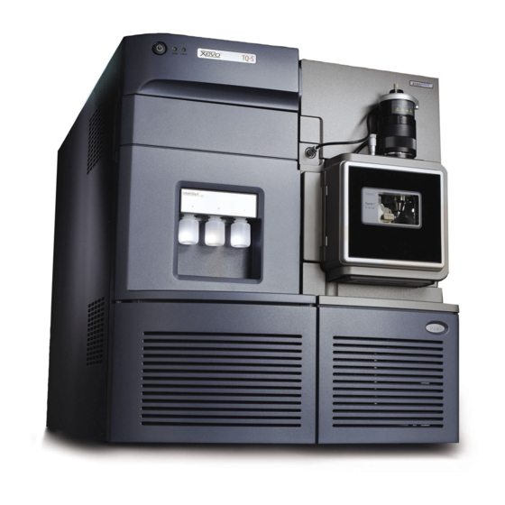
Source enclosure release Xevo TQ-S Sample manager Access door to the fluidics pump Binary solvent manager Non-ACQUITY devices for use with the Xevo TQ-S ® The following non-ACQUITY LC devices are validated for use with the Xevo TQ-S: • Waters Alliance 2695 separations module •... -
Page 21: Software And Data System
The Instrument Console functions independently of MassLynx software and does not recognize or control the data systems. See the Instrument Console system online Help for details. Waters Xevo TQ-S... -
Page 22: Electrospray Ionization (Esi)
The reservoirs can also deliver sample through direct or combined infusion to enable optimization at analytical flow rates. • From a wash reservoir that contains solvent for automated flushing of the instrument’s solvent delivery system. For further information on the IntelliStart Fluidics system, see Appendix Waters Xevo TQ-S Overview... -
Page 23: System Components
IntelliStart Fluidics system: Probe Diverter valve 6-port selector valve Sample loop Column Waste Wash Pump reservoir reservoir Reservoirs System components The onboard system incorporates a 6-port selector valve, a multi-position diverter valve, a pump, and three sample reservoirs. The sample reservoirs are mounted on the instrument’s front panel. When you select a solvent from the Instrument Console, a light-emitting diode (LED) illuminates the appropriate reservoir. -
Page 24: Ion Optics
Any fragment ions can then be mass-analyzed by the second quadrupole. The transmitted ions are detected by the photomultiplier detection system. The signal is amplified, digitized, and sent to the MassLynx mass spectrometry software. Waters Xevo TQ-S Overview... -
Page 25: Ms Operating Modes
Ion optics: StepWave Sample cone Sample inlet Conjoined T-Wave T-Wave/ScanWave Conversion ion guide ion guide collision cell dynode Isolation valve Z-Spray ion source Source sampling Quadrupole 1 Quadrupole 2 Detector orifice (MS1) (MS2) MS operating modes The following table shows the MS operating modes. MS operating modes: Operating mode Collision cell... -
Page 26: Ms/Ms Operating Modes
RADAR™ is an additional mode with which you collect data from the MRM and full scan MS modes simultaneously. RADAR mode can also acquire all detectable ions in both positive and negative full scan MS. 1-10 Waters Xevo TQ-S Overview... -
Page 27: Product (Daughter) Ion Mode
Product (daughter) ion mode Product ion mode is the most commonly used MS/MS operating mode. You can specify an ion of interest for fragmentation in the collision cell, thus yielding structural information. Product ion mode: Collision cell Static (at precursor mass) Pass all masses Scanning Typical applications... -
Page 28: Precursor (Parent) Ion Mode
Multiple reaction monitoring mode: Collision cell Static (at precursor mass) Pass all masses Static (at product mass) 1-12 Waters Xevo TQ-S Overview... -
Page 29: Constant Neutral Loss Mode
Typical application MRM mode is appropriate for quantitative assays in a wide range of biological matrices. MRM mode does not produce a spectrum, because only one transition is monitored at a time. As in SIR mode, a chromatogram is produced. Constant neutral loss mode Constant neutral loss mode detects the loss of a specific neutral fragment or functional group from an unspecified precursor(s). -
Page 30: Scanwave Daughter Scan Mode
1-11. Leak sensors Leak sensors in the drip trays of the Xevo TQ-S continuously monitor the instrument for leaks. A leak sensor stops system flow when its optical sensor detects about 1.5 mL of accumulated leaked liquid in its surrounding reservoir. -
Page 31: Rear Panel
Vacuum leaks and electrical or vacuum pump failures cause vacuum loss, which protective interlocks guard against. The system monitors the turbomolecular pump speeds and continuously measures vacuum pressure with built-in Pirani and Penning gauges. The gauges also serve as switches, stopping operation when vacuum loss is sensed. - Page 32 1-16 Waters Xevo TQ-S Overview...
- Page 33 Preparing the Mass Spectrometer for Operation This chapter describes how to start and shut down the mass spectrometer. Contents: Topic Page Starting the mass spectrometer Preparing the IntelliStart Fluidics system Rebooting the mass spectrometer Leaving the mass spectrometer ready for operation 2-10 Emergency shutdown of the mass spectrometer 2-11...
-
Page 34: Preparing The Mass Spectrometer For Operation
Starting the mass spectrometer This instrument is compatible with the ACQUITY UPLC system; if you are not using an ACQUITY UPLC system, refer to the documentation relevant to the system you are using (see “Non-ACQUITY devices for use with the Xevo TQ-S”... - Page 35 Power-on the ACQUITY UPLC system workstation, and log in. Press the power switch on the top, left-hand side of the mass spectrometer and ACQUITY instruments. Each system instrument runs a series of startup tests. Result: Allow 3 minutes for the embedded PC to initialize. An audible alert sounds when the PC is ready.
-
Page 36: Verifying The Instrument's State Of Readiness
10. Click Resolve or Operate When the mass spectrometer is in good operating condition, Result: IntelliStart software displays “Ready” in the Instrument Console. If clicking Resolve fails to put the instrument in Operate mode, Tip: IntelliStart software displays corrective actions in the instrument console. -
Page 37: Running The Mass Spectrometer At High Flow Rates
Running the mass spectrometer at high flow rates The ACQUITY UPLC system runs at high flow rates. To optimize desolvation, and thus sensitivity, run the ACQUITY Xevo TQ-S system at appropriate gas flows and desolvation temperatures. IntelliStart software automatically sets these parameters when you enter a flow rate, according to the following table. - Page 38 To install the reservoir bottles: The reservoir bottles can be contaminated with Warning: biohazardous and/or toxic materials. Always wear chemical-resistant, powder-free gloves while performing this procedure. Remove the reservoir bottle caps. Screw the reservoir bottles onto the mass spectrometer, as shown below. Reservoir bottle Solvent delivery tube For each reservoir bottle, ensure that the end of the solvent delivery...
- Page 39 To install the low-volume vials The reservoir bottles can be contaminated with Warning: biohazardous and/or toxic materials. Always wear chemical-resistant, powder-free gloves while performing this procedure. If a standard reservoir bottle is fitted, remove it. Screw the low-volume adaptors into the manifold, and finger tighten them.
-
Page 40: Adjusting The Solvent Delivery Tube Positions
Adjusting the solvent delivery tube positions For correct operation of the IntelliStart Fluidics system, you must adjust each solvent delivery tube so that its end is close to, but does not, touch, the bottom of the reservoir bottle or low volume vial. To adjust the position of a solvent delivery tube: Open the access door to the fluidics pump (see the figure on page... -
Page 41: Purging The Infusion Pump
Purging the infusion pump Whenever you replace a solution bottle, purge the infusion pump with the solution that you are going to use next (see the mass spectrometer’s online Help for details). Ensure that the end of the tubing is fully submerged in the Requirement: solvent in the wash reservoir. -
Page 42: Leaving The Mass Spectrometer Ready For Operation
Insert a short length (7.5 cm) of PEEK™ tubing, or similar object, into the reset button aperture to operate the reset button. Reset button aperture Remove the PEEK tubing from the reset button aperture. Close the mass spectrometer’s door. Wait until the reboot sequence ends before starting the MassLynx software. -
Page 43: Emergency Shutdown Of The Mass Spectrometer
Emergency shutdown of the mass spectrometer To shut down the mass spectrometer in an emergency: The instrument’s power switch does not isolate it from the Warning: main power supply. To isolate the instrument, disconnect the power cable from the back of the instrument. Data can be lost during an emergency shutdown. - Page 44 2-12 Preparing the Mass Spectrometer for Operation...
-
Page 45: Esi Operation
ESI Operation This chapter describes how to prepare the mass spectrometer for ESI (electrospray ionization). Contents: Topic Page Electrospray Ionization... -
Page 46: Electrospray Ionization
Electrospray Ionization For further details, see “Electrospray ionization (ESI)” on page 1-6. The following sections explain how to install and remove an ESI probe. Installing the ESI probe Required materials • Chemical-resistant, powder-free gloves • Sharp knife or PEEK tubing cutter To install the ESI probe: The LC system connections, ESI probe, and source can Warning:... - Page 47 With the probe label facing you, carefully slide the ESI probe into the hole in the probe adjuster assembly, ensuring that the probe location dowel aligns with the location hole of the probe adjuster assembly. Probe label Probe location dowel Location hole of the probe adjuster assembly TP03129...
- Page 48 ESI probe, mounted on the source enclosure: Vernier probe adjuster ESI probe Probe locking ring ESI probe cable Vertical probe High voltage adjuster connector Source window Source enclosure release TP03128 To avoid nitrogen leakage, fully tighten the probe locking Caution: ring.
- Page 49 Requirements: • If you are replacing the tubing supplied with the instrument, you must minimize the length of the tube connecting the diverter valve to the ESI probe. Doing so minimizes delays and dispersion. • When cutting the tubing to length, cut it squarely (that is, perpendicular to its horizontal axis).
-
Page 50: Removing The Esi Probe
Removing the ESI probe Required materials Chemical-resistant, powder-free gloves To remove the ESI probe: The LC system connections, ESI probe, and source can Warning: be contaminated with biohazardous and/or toxic materials. Always wear chemical-resistant, powder-free gloves while performing this procedure. To avoid electric shock, ensure that the instrument is Warning: prepared for working on the source before commencing this procedure. - Page 51 Slide closed the instrument’s source interface door. 10. Remove the ESI probe from the source (see page 3-6). 11. Slide open the instrument’s source interface door (see the figure on page 1-4). 12. Slide closed the instrument’s source interface door. Electrospray Ionization...
- Page 52 ESI Operation...
-
Page 53: Maintenance Procedures
Maintenance Procedures This chapter provides the maintenance guidelines and procedures necessary to maintain the instrument’s performance. Keep to a maintenance schedule, and perform maintenance as required and described in this chapter. Contents: Topic Page Maintenance schedule Spare parts Troubleshooting with Connections INSIGHT Safety and handling Preparing the instrument for working on the source Removing and refitting the source enclosure... -
Page 54: Maintenance Schedule
Maintenance schedule The following table lists periodic maintenance schedules that ensure optimum instrument performance. Maintenance schedule: Procedure Frequency For information... Clean the instrument case. As required. page 4-14. Empty the nitrogen exhaust Check daily, empty as page 4-14. trap bottle. required. -
Page 55: Spare Parts
Replace the air filters. Annually. page 4-90. Spare parts Waters recommends that you replace only the parts mentioned in this document. For spare parts details, see the Waters Quality Parts Locator on the Waters Web site’s Services/Support page. Spare parts... -
Page 56: Troubleshooting With Connections Insight
Connections INSIGHT is an “intelligent” device management (IDM) Web service that enables Waters to provide proactive service and support for the ACQUITY UPLC system. To use Connections INSIGHT, you must install its service agent software on your MassLynx workstation. In a client/server system, the service agent must also be installed on the computer from which you control the system. -
Page 57: Safety And Handling
Safety and handling Bear in mind the following safety considerations when performing maintenance procedures: The instrument components can be contaminated with Warning: biologically hazardous materials. Always wear chemical-resistant, powder-free gloves while handling the components. To prevent injury, always observe Good Laboratory Practice Warning: when handling solvents, changing tubing, or operating the instrument. -
Page 58: Preparing The Instrument For Working On The Source
In the Instrument Console, click Stop Flow to stop the LC flow, or if column flow is required, divert the LC flow to waste as follows: In the Instrument Console system tree, expand Xevo TQ-S Detector, Interactive Fluidics. Click Control Select Waste as the flow state. -
Page 59: Removing And Refitting The Source Enclosure
Removing and refitting the source enclosure Removing the source enclosure from the instrument Required materials Chemical-resistant, powder-free gloves To remove the source enclosure: The source components can be contaminated with Warning: biohazardous and/or toxic materials. Always wear chemical-resistant, powder-free gloves while performing this procedure. - Page 60 Using both hands, grasp the source enclosure, and lift it vertically off the two supporting studs on the source adaptor housing. Cable storage positions Supporting stud TP03164 Source enclosure Store the cables neatly by plugging them into the cable-storage positions on the rear of the source enclosure.
-
Page 61: Fitting The Source Enclosure To The Instrument
Fitting the source enclosure to the instrument Required materials Chemical-resistant, powder-free gloves To fit the source enclosure: The source components can be contaminated with Warning: biohazardous and/or toxic materials. Always wear chemical-resistant, powder-free gloves while performing this procedure. Using both hands, fit the source enclosure to the two supporting studs on the source adaptor housing. -
Page 62: Operating The Source Isolation Valve
Operating the source isolation valve You must close the source isolation valve to isolate the source from the instrument vacuum system for certain maintenance procedures. Required materials Chemical-resistant, powder-free gloves To close the source isolation valve before starting a maintenance procedure: The source components can be contaminated with Warning:... - Page 63 Close the source isolation valve by moving its handle counterclockwise, to the vertical position. Isolation valve handle in closed position Operating the source isolation valve 4-11...
- Page 64 To open the source isolation valve after completing a maintenance procedure: The source components can be contaminated with Warning: biohazardous and/or toxic materials. Always wear chemical-resistant, powder-free gloves while performing this procedure. To avoid puncture wounds, take great care while working with Warning: the source enclosure open if an ESI probe is fitted.
-
Page 65: Removing O-Rings And Seals
Removing O-rings and seals When performing certain maintenance procedures, you must remove O-rings or seals from instrument components. An O-ring removal kit is provided with the instrument. O-ring removal kit: Tool 1 Tool 2 To remove an O-ring: When removing an O-ring or seal from a component, be careful Caution: not to scratch the component with the removal tool. -
Page 66: Cleaning The Instrument Case
Cleaning the instrument case Do not use abrasives or solvents to clean the instrument’s case. Caution: Use a soft cloth, dampened with water, to clean the outside surfaces of the mass spectrometer. Emptying the nitrogen exhaust trap bottle Inspect the nitrogen exhaust trap bottle in the instrument’s exhaust line daily, and empty it before it is more than 10% full. - Page 67 Required materials Chemical-resistant, powder-free gloves To empty the nitrogen exhaust trap bottle: In the Instrument Console, click Stop Flow to stop the LC flow. Pull the source enclosure release (located at the bottom, right-hand side) outwards, and swing open the enclosure. The waste liquid in the nitrogen exhaust trap Warning: bottle comprises ACQUITY UPLC solvents and analytes.
-
Page 68: Maintaining The Oerlikon Leybold Oil-Filled Roughing Pumps
Maintaining the Oerlikon Leybold oil-filled roughing pumps In addition to the roughing pump maintenance requirements Requirement: detailed here, refer to the manufacturer’s documentation provided with the instrument. Oerlikon Leybold roughing pump: Oil filler plug Oil level sight glass Gas ballast valve Oil drain plug TP03296 4-16... -
Page 69: Gas Ballasting The Oerlikon Leybold Roughing Pumps
Gas ballasting the Oerlikon Leybold roughing pumps Failure to routinely gas ballast the roughing pumps shortens Caution: oil life and, consequently, pump life. The roughing pumps draw large quantities of solvent vapors that condense in the pump oil, diminishing pumping efficiency. Gas ballasting purges condensed contaminants from the oil. -
Page 70: Inspecting The Roughing Pump Oil Levels
Inspecting the roughing pump oil levels To ensure correct operation of the roughing pumps, do not Caution: operate them with the oil level at less than 30% of the maximum level, as indicated in the pumps’ sight glasses. This procedure does not apply to an Edwards oil-free roughing pump. Note: You must determine the oil levels while the roughing pumps Requirement:... - Page 71 To add oil to a roughing pump: Vent and shut down the mass spectrometer (see the mass spectrometer’s online Help for details). To avoid personal injury, as well as damage to the Warning: roughing pumps and mass spectrometer, disconnect the power cords for the mass spectrometer and roughing pumps from the main power source.
- Page 72 To avoid oil leakage when fitting the oil filler plug to the Caution: roughing pump, • inspect the O-ring on the plug, and verify that it is free of particles. • ensure that the plug is not cross threaded. • do not overtighten the plug. Use the 12-mm Allen wrench to refit the oil filler plug.
-
Page 73: Replacing The Roughing Pumps' Oil And Oil Demister Elements
Replacing the roughing pumps’ oil and oil demister elements Replace the roughing pumps’ oil and oil demister elements annually. This procedure is not required for an Edwards oil-free roughing pump. Note: Required materials • Chemical-resistant, powder-free gloves • 12-mm Allen wrench •... - Page 74 To drain the roughing pumps’ oil: The roughing pump oil can be contaminated with Warning: analyte accumulated during normal operation. Always wear chemical-resistant, powder-free gloves when adding or replacing oil. To avoid burn injuries, take great care while working with the Warning: roughing pumps: they can be hot.
- Page 75 To avoid oil leakage when fitting the oil drain plug to the Caution: roughing pump, • ensure that the plug is not cross threaded. • ensure that the O-ring is not pinched. • do not overtighten the plug. Use the 12-mm Allen wrench to refit the oil drain plug. When the plug is tightened, it seals against an O-ring.
- Page 76 To avoid oil leakage when fitting the oil filler plug to the Caution: roughing pump, • ensure that the plug is not cross threaded. • ensure that the O-ring is not pinched. • do not over tighten the plug. Use the 12-mm Allen wrench to refit the oil filler plug. When the plug is tightened, it seals against an O-ring.
- Page 77 Using both hands, carefully remove the exhaust flange and oil demister element from the roughing pump. Oil demister element TP02693 Use the 10-mm wrench to remove the nut that secures the oil demister element to the exhaust flange. Spring Securing nut TP02686 Maintaining the Oerlikon Leybold oil-filled roughing pumps 4-25...
- Page 78 Holding the oil demister element slightly elevated, to prevent the loss of the spring, remove its flange. TP02692 Remove the spring from the oil demister element. The oil demister element can be contaminated with Warning: biohazardous and/or toxic materials. Ensure that it is correctly disposed of according to local environmental regulations.
- Page 79 To fit the new oil demister elements: The pump oil can be contaminated with analyte Warning: accumulated during normal operation. Always wear chemical-resistant, powder-free gloves when replacing the oil demister element. Do as follows for each pump: Fit the spring to the new oil demister element. TP02682 Holding the oil demister element slightly elevated, to prevent the loss of the spring, fit its exhaust flange.
- Page 80 Do not overtighten the nut that secures the oil demister Caution: element to the exhaust flange. Ensure that only (approximately) 1 mm of exposed thread appears beyond the nut when it is tightened. Use the 10-mm wrench to fit and tighten the nut that secures the oil demister element to the exhaust flange.
- Page 81 To prepare for operation after changing the roughing pumps’ oil and oil demister elements: Connect the power cords for the mass spectrometer and both roughing pumps to the main power source. Start the mass spectrometer (see page 2-2). Gas-ballast the roughing pumps (see page 4-18).
-
Page 82: Gas Ballasting The Edwards Xds46I Oil-Free Roughing Pump
Gas ballasting the Edwards XDS46i oil-free roughing pump In addition to the roughing pump gas ballasting procedure Requirement: detailed here, please refer to the manufacturer’s documentation provided with the instrument. Failure to routinely gas ballast the roughing pump shortens Caution: pump life. -
Page 83: Cleaning The Source Components
Use of the gas ballast control To select no-gas ballast, turn the control position to 0. Doing so pumps gases fully, achieving ultimate vacuum. To select low-flow gas ballast, turn the control to position I. Use this position for these purposes: •... -
Page 84: Cleaning The Sampling Cone Assembly
Cleaning the sampling cone assembly You can remove the sampling cone assembly (comprising the sample cone, O-ring, and cone gas nozzle) for cleaning without venting the instrument. Removing the sampling cone assembly from the source Required materials Chemical-resistant, powder-free gloves To remove the sampling cone assembly from the source: The source components can be contaminated with Warning:... - Page 85 Close the source isolation valve (see page 4-10). Grasp the cone gas nozzle handle, and use it to rotate the sampling cone assembly 90 degrees, moving the handle from the vertical to the horizontal position. Sampling cone assembly Cone gas nozzle handle TP03131 Do not open the isolation valve at any time when the...
-
Page 86: Disassembling The Sampling Cone Assembly
Disassembling the sampling cone assembly Required materials • Chemical-resistant, powder-free gloves • Combined 2.5-mm Allen wrench and cone extraction tool To disassemble the sampling cone assembly: The sampling cone assembly can be contaminated with Warning: biohazardous and/or toxic materials. Always wear chemical-resistant, powder-free gloves while performing this procedure. - Page 87 The sample cone is fragile. Never place it on its tip; Caution: always place it on its flanged base. Rotate and lift the tool and collar to remove the sample cone from the cone gas nozzle. Remove the O-ring from the sample cone. Cone gas nozzle Cone gas nozzle handle O-ring...
-
Page 88: Cleaning The Sample Cone And Cone Gas Nozzle
The O-ring can be contaminated with Warning: biohazardous and/or toxic materials. Dispose of it according to local environmental regulations. If the O-ring shows signs of deterioration or damage, dispose of it in accordance with local environmental regulations. Unscrew and remove the PEEK cone gas nozzle handle from the cone gas nozzle. - Page 89 To clean the sample cone and cone gas nozzle: The sample cone and cone gas nozzle can be Warning: contaminated with biohazardous and/or toxic materials. Always wear chemical-resistant, powder-free gloves while performing this procedure. Formic acid is extremely corrosive and toxic. Work with Warning: extreme care, use a fume hood and suitable protective equipment.
-
Page 90: Assembling The Sampling Cone Assembly
Assembling the sampling cone assembly Required materials Chemical-resistant, powder-free gloves To assemble the sampling cone assembly: Caution: • To avoid recontaminating the sampling cone assembly, wear clean chemical-resistant, powder-free gloves during this procedure. • The sample cone is fragile. Never place it on its tip; always place it on its flanged base. -
Page 91: Fitting The Sampling Cone Assembly To The Source
Fitting the sampling cone assembly to the source Required materials Chemical-resistant, powder-free gloves To fit the sampling cone assembly to the source: The source components can be contaminated with Warning: biohazardous and/or toxic materials. Always wear chemical-resistant, powder-free gloves while performing this procedure. - Page 92 Ion block assembly TP03132 Sampling cone assembly Grasp the cone gas nozzle handle, and use it to rotate the sampling cone assembly 90 degrees, moving the handle downward from the horizontal to the vertical position. Open the source isolation valve (see page 4-12).
-
Page 93: Cleaning The Ion Block Assembly
Cleaning the ion block assembly Clean the ion block assembly if cleaning the sample cone and cone gas nozzle fails to increase signal sensitivity. Removing the ion block assembly from the source assembly Required materials • Chemical-resistant, powder-free gloves • Combined 2.5-mm Allen wrench and cone extraction tool To remove the ion block assembly: The source components can be contaminated with... - Page 94 Use the combined 2.5-mm Allen wrench and cone extraction tool to unscrew the 4, captive, ion block assembly securing screws. Ion block assembly securing screws TP03130 Remove the ion block assembly from the PEEK ion block support. PEEK ion block support Ion block assembly TP03130 4-42...
-
Page 95: Disassembling The Source Ion Block Assembly
Disassembling the source ion block assembly Required materials • Chemical-resistant, powder-free gloves • Combined 2.5-mm Allen wrench and cone extraction tool • O-ring removal kit To disassemble the ion block assembly: The ion block assembly can be contaminated with Warning: biohazardous and/or toxic materials. - Page 96 Use the combined 2.5-mm Allen wrench and cone extraction tool to loosen the 2 captive screws securing the ion block cover plate. Ion block cover plate securing screw Ion block cover plate Remove the ion block cover plate. Grasp the isolation valve, and pull it out of the ion block. Isolation valve O-ring 4-44...
- Page 97 Use the O-ring removal kit to carefully remove the isolation valve O-ring (see page 4-13). The isolation valve O-ring can be contaminated Warning: with biohazardous and/or toxic materials. Dispose of it according to local environmental regulations. If the isolation valve O-ring shows signs of deterioration or damage, dispose of it in accordance with local environmental regulations.
- Page 98 To avoid damaging the heater cartridge assembly wires, Caution: do not bend or twist them when removing the assembly and ceramic heater mounting block from the ion block. 10. Carefully remove the PEEK terminal block and ceramic heater mounting block, complete with heater cartridge assembly, from the ion block.
- Page 99 11. Use the O-ring removal kit to carefully remove the cover seal from the ion block (see also “Removing O-rings and seals” on page 4-13). Cover seal Cone gas O-ring 12. Use the O-ring removal kit to carefully remove the cone gas O-ring from the ion block.
-
Page 100: Cleaning The Ion Block Components
Cleaning the ion block components Required materials • Chemical-resistant, powder-free gloves. • Appropriately sized glass vessels in which to completely immerse components when cleaning. Use only glassware not previously cleaned with surfactants. • HPLC-grade (or better) methanol. • HPLC-grade (or better) water. •... -
Page 101: Assembling The Source Ion Block Assembly
If you used formic acid in the cleaning solution, do as follows: Rinse the components by immersing them separately in glass vessels containing water and then placing the vessels in the ultrasonic bath for 20 minutes. Dry the components by immersing them in separate glass vessels containing methanol and then placing the vessels in the ultrasonic bath for 10 minutes. - Page 102 To assemble the ion block assembly: Caution: • To avoid recontaminating the ion block assembly, wear clean, chemical-resistant, powder-free gloves during this procedure. • To avoid damaging the heater cartridge assembly wires, do not bend or twist them when fitting the assembly and ceramic heater mounting block to the ion block.
-
Page 103: Fitting The Ion Block Assembly To The Source Assembly
Fitting the ion block assembly to the source assembly Required materials • Chemical-resistant, powder-free gloves • Combined 2.5-mm Allen wrench and cone extraction tool To fit the ion block assembly to the source assembly The source components can be contaminated with Warning: biohazardous and/or toxic materials. -
Page 104: Cleaning The Stepwave Ion Guide Assembly
Cleaning the StepWave ion guide assembly Clean the StepWave ion guide assembly if cleaning the ion block and isolation valve fails to increase signal sensitivity. Handling the StepWave ion guide assembly The StepWave ion guide assembly is fragile. Handle it and its Caution: components carefully throughout the cleaning procedure. - Page 105 Use the 3-mm Allen wrench to unscrew and remove the 4 screws securing the PEEK ion block support to the adaptor housing. Adaptor housing PEEK ion block support Securing screws StepWave assembly Remove the PEEK ion block support from the adaptor housing. Use the O-ring removal kit to carefully remove all the O-rings from the PEEK ion block support (see page...
-
Page 106: Removing The Stepwave Assembly From The Source Assembly
Removing the StepWave assembly from the source assembly Required materials • Chemical-resistant, powder-free gloves • Seal breaker and locator tool • StepWave assembly removal and insertion tool When not in use, store the seal breaker and locator tool on Recommendation: the end of the StepWave assembly removal and insertion tool. - Page 107 Seal break and locator tool: Handle Seal breaker and locator tool positioned on the adaptor housing: Ion guide cap Adaptor housing Seal breaker and locator tool Cleaning the StepWave ion guide assembly 4-55...
- Page 108 Push firmly on the seal breaker and locator tool’s handle, to lever the StepWave assembly slightly out of the adaptor housing. Moving the assembly in this manner releases it from a seal Rationale: located inside the instrument. With the StepWave removal and insertion tool’s cutout uppermost, insert the tool’s pins into the ion block support screw holes above and below the aperture in the pumping block assembly.
-
Page 109: Disassembling The Stepwave Ion Guide Assembly
The StepWave ion guide assembly is fragile; handle it Caution: with care. Remove the StepWave ion guide assembly from the StepWave removal and insertion tool. Using both hands, fit the source enclosure to the two supporting studs on the source adaptor housing. Close the source enclosure. - Page 110 To disassemble the StepWave ion guide assembly: The source components can be contaminated with Warning: biohazardous and/or toxic materials. Always wear chemical-resistant, powder-free gloves while performing this procedure. The StepWave ion guide assembly is fragile; handle it and its Caution: components carefully throughout this procedure.
- Page 111 Separate the first and second ion guide assemblies. First ion guide assembly Second ion guide assembly Lay the clean, lint-free cloth on a bench, and then place the second ion guide assembly, upside down, on the cloth. Cleaning the StepWave ion guide assembly 4-59...
- Page 112 To avoid damaging the second ion guide assembly, Caution: prevent the support rods turning when removing the screws that secure the differential aperture to the assembly. On the second ion guide assembly, insert the 3-mm Allen wrench through one of the holes in one of the support rods. 3-mm Allen wrench Support rod Brown PEEK gasket...
- Page 113 Remove the brown PEEK gasket and insulators from the second ion guide assembly. Brown PEEK gasket PEEK insulators Second ion guide assembly Remove the O-ring from the differential pumping aperture. Differential pumping aperture O-ring Slotted screw The O-ring can be contaminated with Warning: biohazardous and/or toxic materials.
-
Page 114: Cleaning The Stepwave Ion Guide Assembly
10. Use the small, flat-blade screwdriver to remove the 4 slotted screws that secure the differential pumping aperture to the second ion guide PCB assembly. 11. Remove the differential pumping aperture, complete with support rods, from the second ion guide PCB assembly. Intermediate differential aperture Second ion guide PCB assembly... - Page 115 • Appropriately sized glass vessels in which to completely immerse the smaller StepWave assembly components when cleaning. Use only glassware not previously cleaned with surfactants. • Two lengths of small diameter PEEK or PTFE tubing appropriately sized for suspending the StepWave first ion guide and second ion guide PCB assemblies in the glass vessels when cleaning.
- Page 116 Hook First ion guide assembly Add 1:1 methanol/water to the glass vessel until the first ion guide assembly is immersed completely. Repeat step 1 through step 3 for the second ion guide PCB assembly, placing the hook through one of the screw holes on the assembly. Hook Second ion guide PCB assembly 4-64...
- Page 117 Place the vessels containing the first ion guide and second ion guide PCB assemblies in the ultrasonic bath for 30 minutes. To avoid recontaminating the first ion guide and second Caution: ion guide PCB assemblies, wear clean, chemical-resistant, powder-free gloves for the rest of this procedure. Carefully remove the first ion guide assembly from its vessel, and blow-dry it using inert, oil-free gas.
-
Page 118: Assembling The Stepwave Ion Guide Assembly
If you used formic acid in the cleaning solution, rinse the differential pumping aperture by immersing it, with support rods, in a glass vessel containing water and then placing the vessel in the ultrasonic bath for 20 minutes. To avoid recontaminating the first ion guide assembly, Caution: wear clean, chemical-resistant, powder-free gloves for the following step. - Page 119 Fit the brown PEEK gasket and insulators to the second ion guide assembly. Ensure that the brown PEEK gasket is orientated correctly. Tip: Brown PEEK gasket PEEK insulators On the second ion guide assembly, insert the 3-mm Allen wrench through one of the holes in one of the support rods. To avoid damaging the second ion guide assembly, Caution: prevent the support rods turning when fitting the screws that...
-
Page 120: Fitting The Stepwave Assembly To The Source Assembly
Fitting the StepWave assembly to the source assembly Required materials • Chemical-resistant, powder-free gloves • Seal breaker and locator tool • StepWave assembly removal and insertion tool To fit the StepWave assembly to the source assembly: The source components can be contaminated with Warning: biohazardous and/or toxic materials. - Page 121 StepWave assembly Cutout Pins StepWave assembly removal and insertion tool With the StepWave removal and insertion tool’s cutout uppermost, insert the StepWave removal and insertion tool’s pins into the ion block support screw holes above and below the aperture in the pumping block assembly.
-
Page 122: Fitting The Ion Block Support To The Source
Invert the seal breaker and locator tool, and locate it over the end of the StepWave assembly. Inverted seal breaker and locator tool StepWave assembly Adaptor housing Push firmly on the seal breaker and locator tool until the tool’s face contacts the adaptor housing. -
Page 123: Replacing The Esi Probe Tip And Gasket
To fit the PEEK ion block support to the source: The source components can be contaminated with Warning: biohazardous and/or toxic materials. Always wear chemical-resistant, powder-free gloves while performing this procedure. Ensure that the grooves for the PEEK ion block support O-rings are free from dirt and debris. - Page 124 To remove the ESI probe tip and gasket: The probe and source components can be contaminated Warning: with biohazardous and/or toxic materials. Always wear chemical-resistant, powder-free gloves while performing this procedure. The probe and source can be hot. To avoid burn injuries, take Warning: great care while performing this procedure.
- Page 125 If the probe tip is difficult to remove, use the 7-mm wrench in Tip: conjunction with the 10-mm wrench. 7-mm wrench 10-mm wrench Probe tip Remove the metal gasket from the probe tip. Metal gasket The probe tip and metal gasket can be Warning: contaminated with biohazardous and/or toxic materials.
-
Page 126: Fitting The Esi Probe Tip And Gasket
Fitting the ESI probe tip and gasket Required materials • Chemical-resistant, powder-free gloves • 10-mm wrench • New metal gasket To fit the ESI probe tip and gasket The probe and source components can be contaminated Warning: with biohazardous and/or toxic materials. Always wear chemical-resistant, powder-free gloves while performing this procedure. -
Page 127: Replacing The Esi Probe Sample Capillary
Replacing the ESI probe sample capillary Replace the stainless steel sample capillary in the ESI probe if it becomes blocked and cannot be cleared, or if it becomes contaminated or damaged. Removing the existing capillary Required materials • Chemical-resistant, powder-free gloves •... - Page 128 Use the combined 2.5-mm Allen wrench and cone extraction tool to remove the 3 probe end-cover retaining screws. End-cover retaining screws Remove the end cover and gasket from the probe assembly. Nebulizer adjuster knob Gasket End cover Unscrew and remove the nebulizer adjuster knob. 4-76 Maintenance Procedures...
- Page 129 Use the 10-mm wrench to remove the probe tip. 10-mm wrench Probe tip If the probe tip is difficult to remove, use the 7-mm wrench in Tip: conjunction with the 10-mm wrench. 7-mm wrench 10-mm wrench Probe tip Replacing the ESI probe sample capillary 4-77...
- Page 130 Remove the metal gasket from the probe tip. Metal gasket Remove the PEEK union/UNF coupling assembly and capillary from the probe. PEEK union/UNF coupling assembly Capillary Unscrew and remove the knurled collar from the UNF coupling. PEEK union UNF coupling Locknut Knurled collar Conductive sleeve...
-
Page 131: Installing The New Capillary
12. Unscrew the finger-tight PEEK union from the UNF coupling. Ferrule PTFE liner sleeve 13. Remove the ferrule and PTFE liner sleeve from the capillary. 14. Remove the capillary from the UNF coupling. The capillary, PTFE liner sleeve, and ferrule can Warning: be contaminated with biohazardous and/or toxic materials. - Page 132 To install the new capillary The probe and source components can be contaminated Warning: with biohazardous and/or toxic materials. Always wear chemical-resistant, powder-free gloves while performing this procedure. The ESI probe tip is sharp. To avoid puncture wounds, Warning: handle the probe with care. Use the sharp knife or PEEK tubing cutter to cut an approximately 60 cm (24 inches) piece of red, PEEK tubing.
- Page 133 Insert the capillary in the PEEK union, and ensure that it is fully seated. Screw the UNF coupling into the PEEK union, finger-tight only. Gently tug on the capillary, testing to ensure that it stays in place. Use the 7-mm wrench to tighten the locknut against the PEEK union until the union can no longer be twisted.
- Page 134 15. Carefully push the PEEK union/UNF coupling assembly and capillary into the probe assembly so that the locating pin on the UNF coupling is fully engaged in the locating slot at the head of the probe assembly. UNF coupling locating pin Probe assembly locating slot 16.
-
Page 135: Replacing The Ion Block Source Heater
Replacing the ion block source heater Replace the ion block source heater if it fails to heat when the instrument is pumped down (evacuated). Required materials • Chemical-resistant, powder-free gloves • Combined 2.5-mm Allen wrench and cone extraction tool • Needle-nose pliers •... - Page 136 Use the combined 2.5-mm Allen wrench and cone extraction tool to loosen the 2 captive screws securing the ion block cover plate. Ion block cover plate securing screw Ion block cover plate Remove the ion block cover plate. Use the combined 2.5-mm Allen wrench and cone extraction tool to loosen the captive PEEK terminal block securing screw.
- Page 137 To avoid damaging the heater cartridge assembly wires, Caution: do not bend or twist them when removing the assembly and ceramic heater mounting block from the ion block. Carefully remove the PEEK terminal block and ceramic heater mounting block, complete with heater cartridge assembly, from the ion block.
- Page 138 Use the needle-nose pliers to gently grasp the heat-shrink tubing on the heater cartridge assembly, and slide the assembly out of the ceramic heater mounting block. Heat-shrink tubing Heater cartridge assembly Ceramic heater mounting block 10. Dispose of the heater cartridge assembly. To avoid damaging the heater cartridge assembly wires, Caution: do not bend or twist them when fitting the assembly to the ceramic...
-
Page 139: Replacing The Source Assembly Seals
Replacing the source assembly seals To avoid excessive leakage of solvent vapor into the Warning: laboratory atmosphere, the seals listed below must be renewed, at intervals of no greater than 1 year, exactly as described in this section. To avoid excessive leakage of solvent vapor into the laboratory atmosphere, the following seals must be renewed at intervals of no greater than 1 year: •... - Page 140 Probe adjuster nebulizer gas seal Probe adjuster assembly probe seal Use the O-ring removal kit to carefully remove the following seals from the source enclosure: • Source enclosure seal • Nebulizer gas seal • Desolvation gas seal Nebulizer gas seal Desolvation gas seal Source enclosure seal TP03164...
-
Page 141: Fitting The New Source Enclosure And Probe Adjuster Assembly Probe Seals
The seals can be contaminated with biohazardous Warning: and/or toxic materials. Dispose of them according to local environmental regulations. Dispose of all the seals in accordance with local environmental regulations. Fitting the new source enclosure and probe adjuster assembly probe seals Required materials •... -
Page 142: Replacing The Air Filter
Fit the following new seals to the source enclosure: • Nebulizer gas seal • Desolvation gas seal These seals have a special cross-section; fit them in the Requirement: groove as shown. Seal Groove Fit the following new seals to the probe adjuster assembly: •... - Page 143 Unscrew the captive thumbscrew on the filter cover. Thumbscrew Filter cover Remove the filter cover from the instrument. Filter Filter cover Replacing the air filter 4-91...
- Page 144 Lift the filter, vertically, from the its slot in the instrument. If necessary, use the needle-nose files to grasp the filter. Tip: Dispose of the filter. Fit the new filter into the instrument. Fit the filter cover to the instrument. Tighten the thumbscrew on the filter cover.
- Page 145 This appendix presents all the safety symbols and statements that apply to the entire line of Waters products. Contents: Topic...
-
Page 146: A Safety Advisories
Heed all warnings when you install, repair, and operate Waters instruments. Waters assumes no liability for the failure of those who install, repair, or operate its instruments to comply with any safety precaution. -
Page 147: Specific Warnings
The following warnings can appear in the user manuals of particular instruments and on labels affixed to them or their component parts. Burst warning This warning applies to Waters instruments fitted with nonmetallic tubing. Pressurized nonmetallic, or polymer, tubing can burst. Warning: Observe these precautions when working around such tubing: •... - Page 148 Biohazard warning This warning applies to Waters instruments that can be used to process material that can contain biohazards: substances that contain biological agents capable of producing harmful effects in humans.
-
Page 149: Caution Symbol
Chemical hazard warning This warning applies to Waters instruments that can process corrosive, toxic, flammable, or other types of hazardous material. Waters instruments can be used to analyze or Warning: process potentially hazardous substances. To avoid injury with any of these materials, familiarize yourself with the materials and their hazards, observe Good Laboratory Practice (GLP), and consult your organization’s safety... -
Page 150: Warnings That Apply To All Waters Instruments
Warnings that apply to all Waters instruments When operating this device, follow standard quality-control procedures and the equipment guidelines in this section. Attention: Changes or modifications to this unit not expressly approved by the party responsible for compliance could void the user’s authority to operate the equipment. - Page 151 • Keine Schläuche verwenden, die stark geknickt oder überbeansprucht sind. • Nichtmetallische Schläuche nicht für Tetrahydrofuran (THF) oder konzentrierte Salpeter- oder Schwefelsäure verwenden. • Durch Methylenchlorid und Dimethylsulfoxid können nichtmetallische Schläuche quellen; dadurch wird der Berstdruck des Schlauches erheblich reduziert. Warnings that apply to all Waters instruments...
- Page 152 Attenzione: fare attenzione quando si utilizzano tubi in materiale polimerico sotto pressione: • Indossare sempre occhiali da lavoro protettivi nei pressi di tubi di polimero pressurizzati. • Spegnere tutte le fiamme vive nell'ambiente circostante. • Non utilizzare tubi eccessivamente logorati o piegati. •...
- Page 153 Advertencia: el usuario deberá saber que si el equipo se utiliza de forma distinta a la especificada por el fabricante, las medidas de protección del equipo podrían ser insuficientes. Warnings that apply to all Waters instruments...
-
Page 154: Electrical And Handling Symbols
Electrical and handling symbols Electrical symbols These can appear in instrument user manuals and on the instrument’s front or rear panels. Electrical power on Electrical power off Standby Direct current Alternating current Protective conductor terminal Frame, or chassis, terminal Fuse Recycle symbol: Do not dispose in municipal waste. -
Page 155: Handling Symbols
Handling symbols These handling symbols and their associated text can appear on labels affixed to the outer packaging of Waters instrument and component shipments. Keep upright! Keep dry! Fragile! Use no hooks! Electrical and handling symbols A-11... - Page 156 A-12 Safety Advisories...
- Page 157 Mass spectrometer external wiring and vacuum connections Connecting the Oerlikon Leybold oil-filled roughing pumps Connecting the Edwards oil-free roughing pumps B-10 Making the roughing pump connections to the Xevo TQ-S B-16 Connecting to the nitrogen supply B-17 Connecting to the collision cell gas supply...
-
Page 158: B External Connections
Mass spectrometer external wiring and vacuum connections The instrument’s rear panel connectors are shown below. Connectors and controls not identified in the following figure are for Note: Waters engineers use only. Mass spectrometer rear panel connectors: Shielded Ethernet LA N External Connections 1... -
Page 159: Connecting The Oerlikon Leybold Oil-Filled Roughing Pumps
Connecting the Oerlikon Leybold oil-filled roughing pumps ® This option requires the use of two, identical, Oerlikon Leybold™, oil-filled roughing pumps. To connect the alternative, oil-free roughing pumps, see page B-10. Note: Oerlikon Leybold oil-filled roughing pump: Electrical connections Inlet port Exhaust port TP03296 Connecting the Oerlikon Leybold oil-filled roughing pumps... -
Page 160: Making Tubing Connections
Making tubing connections Required materials • Chemical-resistant, powder-free gloves • 7-mm nut driver • Sharp knife ® The following items are included in the Xevo TQ-S installation kit: • NW40 flanged flexible tubing, 1-m long • NW40 hose assembly, 1.5-m long •... - Page 161 To make the tubing connections: The pumps and their connections can be contaminated Warning: with biohazardous and/or toxic materials. Always wear chemical-resistant, powder-free gloves when performing this procedure. Caution: • To ensure correct operation of the roughing pumps, install each pump within 2 degrees of horizontal.
- Page 162 The roughing pumps are heavy. To avoid injury, at least Warning: two people must lift each pump. Place the pumps on the PTFE drip tray, facing the same orientation. To Xevo TQ-S source vacuum port To Xevo TQ-S turbo NW40 flanged NW40 hose...
- Page 163 NW40 clamp, tightening it with the 7-mm nut driver. Make the connections between the NW25 and NW40 hose assemblies and the vacuum ports on the rear of the Xevo TQ-S (see page B-16). To avoid gas leaks, use the sharp knife to cut the PVC...
- Page 164 The instrument requires two separate exhaust systems: Caution: one for nitrogen, the other for the roughing pump. Vent them to atmosphere through separate exhaust lines. Oil mist can seriously damage the instrument if the nitrogen exhaust line connects with the roughing pump exhaust line. Your warranty does not cover damage caused by routing exhaust lines incorrectly.
- Page 165 LA N External Connections 1 Service Bus EPC Com Port External Connections 2 Video Output OUT - External Connections 1 External Connections 2 Auxiliary 10MB Activity /100MB Roughing pump number 2 Top roughing pump connector Roughing pump number 1 Roughing pump d.c.
-
Page 166: Connecting The Edwards Oil-Free Roughing Pumps
Connecting the Edwards oil-free roughing pumps This option requires the use of two, Edwards™, oil-free roughing pumps (types XDS46i and XDS100B) as an alternative to the oil-filled roughing pumps. To connect the oil-filled roughing pumps, see “Connecting the Oerlikon Note: Leybold oil-filled roughing pumps”... - Page 167 Required materials • Chemical-resistant, powder-free gloves • 7-mm nut driver The following items are included in the Xevo TQ-S installation kit: • NW40 flanged flexible tubing, 1 m long • NW40 hose assembly, 1.5 m long • NW25 hose assembly, 1.5 m long •...
- Page 168 To connect the oil-free roughing pumps: The pumps and connections can be contaminated with Warning: biohazardous and/or toxic materials. Always wear chemical-resistant, powder-free gloves when performing this procedure. The roughing pumps are heavy. To avoid injury, at least two Warning: people must lift each pump.
- Page 169 To Xevo TQ-S source vacuum port To Xevo TQ-S turbo vacuum port NW40 hose NW40 flanged assembly flexible tubing NW25 hose assembly NW25/NW40 adaptor NW40 tee To exhaust vent XDS100B pump XDS46i pump PVC exhaust tubing Using an NW40 center ring, attach one end of the 1-m length of NW40...
- Page 170 XDS100B pump, and then secure the connection with an NW40 clamp, tightening it with the 7-mm nut driver. Make the connections between the NW25 and NW40 hose assemblies and the vacuum ports on the rear of the Xevo TQ-S (see page B-16).
- Page 171 LA N External Connections 1 Service Bus EPC Com Port External Connections 2 Video Output OUT - External Connections 1 External Connections 2 Auxiliary 10MB Activity /100MB Roughing pump connectors XDS100B pump XDS46i pump Roughing pump main power connector Roughing pump d.c.
-
Page 172: Making The Roughing Pump Connections To The Xevo Tq-S
Using an NW25 center ring, attach the NW25 elbow to the turbo vacuum port of the Xevo TQ-S, and then secure the connection with an NW25 clamp, tightening it with the 7-mm nut driver, see the figure on page B-17. -
Page 173: Connecting To The Nitrogen Supply
Connecting to the nitrogen supply Required materials • Chemical-resistant, powder-free gloves • 6-mm PTFE tubing (included in the Waters Installation Kit) • Nitrogen regulator To connect the nitrogen supply: Connect one end of the 6-mm PTFE tubing to the nitrogen inlet port on the rear of the instrument. -
Page 174: Connecting To The Collision Cell Gas Supply
Connecting to the collision cell gas supply Required materials • Chemical-resistant, powder-free gloves • 11-mm wrench ® • 1/8-inch Swagelok nut and ferrule • 1/8-inch stainless steel tube (supplied with the mass spectrometer) • Argon regulator (not supplied) To connect the collision cell gas supply: Use the 1/8-inch Swagelok nut and ferrule to connect the 1/8-inch stainless steel tube to the collision cell gas inlet on the rear of the mass spectrometer (see the figure on... -
Page 175: Connecting The Nitrogen Exhaust Line
Connecting the nitrogen exhaust line Required materials • Chemical-resistant, powder-free gloves • Sharp knife • Nitrogen exhaust trap bottle • 4-mm and 12-mm PTFE tubing (included in the installation kit) To connect the nitrogen exhaust line: Warning: • Biohazardous and/or toxic LC solvents and analytes can be carried in the nitrogen exhaust, which must be vented via the nitrogen exhaust trap bottle and laboratory exhaust system. - Page 176 Nitrogen exhaust trap bottle: To laboratory exhaust port From instrument exhaust connection From instrument pilot valve port Nitrogen exhaust trap bottle Bottle support To avoid gas leaks, use the sharp knife to cut the PTFE Caution: tubing squarely (that is, perpendicular to its horizontal axis). Cut a length of 4-mm tubing long enough to connect the instrument to the nitrogen exhaust trap bottle.
- Page 177 Connect one end of the tubing to the exhaust port on the instrument’s rear panel. Connect the free end of the tubing to the inlet port on the nitrogen exhaust trap bottle. Requirement: Ensure that the tubing has no loops and does not sag. To avoid gas leaks, use the sharp knife to cut the PTFE Caution: tubing squarely (that is, perpendicular to its horizontal axis).
-
Page 178: Connecting The Liquid Waste Line
Connecting the liquid waste line Required materials • Chemical-resistant, powder-free gloves • Waste container To connect the liquid waste line: The waste line and connection can be contaminated with Warning: biologically hazardous materials. Always wear chemical-resistant, powder-free gloves while performing this procedure. Place a suitable waste container below the mass spectrometer. - Page 179 To prevent leakage of biologically hazardous Warning: materials, • do not crimp or bend drain line. A crimp or bend can impede flow to the waste container. • empty the waste container before the lower end of the drain tube is covered by waste solvent. Route the waste line to the waste container.
-
Page 180: Connecting The Workstation
Connecting the workstation Before connecting the workstation to the instrument, set up the workstation according to its accompanying instructions. Locate the workstation within 5 meters of the instrument. Use shielded network cables with the mass spectrometer to Requirement: ensure compliance with FCC limits. To connect the workstation: Connect the monitor to the PC. -
Page 181: Connecting Ethernet Cables
Connecting Ethernet cables Use shielded network cables with the mass spectrometer to Requirement: ensure compliance with FCC limits. To make Ethernet connections: Connect one end of one shielded Ethernet cable to the network switch, and then connect the other end to the Ethernet card on the ®... - Page 182 Input and output connector locations: LA N External Connections 1 Service Bus External connections identification tables EPC Com Port External Connections 2 Video Output OUT - External connections 1 External Connections 1 External connections 2 External Connections 2 System Activity Input/output signal connector configuration: B-26 External Connections...
- Page 183 External connections 1: Function Rating Event In 1+, digital signal, optimum +3.3V +5 V max +5V Event In 1-, digital ground, 0V Not used Event In 2+, digital signal, optimum +3.3V +5 V max +5V Event In 2-, digital ground, 0V Not used Not used CE Interlock Out, common...
-
Page 184: Making Signal Connections
Making signal connections Mass spectrometer signal connections: Signal connections Description Analog (Out) Used for analog chart output functionality. The output voltage range is 0 to 1 V. The resolution of the voltage output is 12 bits. Gas Fail Interlock Used to stop the solvent flow if the nitrogen gas (Out) supply fails. - Page 185 Attach the positive and negative leads of the signal cable to the connector. Connector Signal cable TP02585 Slide the clamp (with the bend facing down) into the protective shield. Insert the clamp and shield (with the bend facing down) into the connection cover, and loosely tighten with one self-tapping screw.
- Page 186 Insert the connector with the signal cable into the connection cover, position the clamp over the cable leads, and tighten the clamp into place with the second self-tapping screw. Cable leads Clamp TP02587 Place the second connection cover over the first cover, and snap it into place.
-
Page 187: Connecting To The Electricity Source
To avoid electric shock, use the SVT-type power cord in the Warning: United States and HAR-type (or better) in Europe. For information regarding what cord to use in other countries, contact your local Waters distributor. Connect the female end of the power cord to the receptacle on the rear panel of the mass spectrometer. - Page 188 B-32 External Connections...
- Page 189 Materials of Construction and Compatible Solvents To confirm the integrity of the source exhaust Warning: system, you must address any safety issues raised by the contents of this Appendix. Contents: Topic Page Preventing contamination Items exposed to solvent Solvents used to prepare mobile phases...
-
Page 190: C Materials Of Construction And Compatible Solvents
Preventing contamination For information on preventing contamination, refer to Controlling Contamination in LC/MS Systems (part number 715001307). Visit www.waters.com. Items exposed to solvent The items that appear in the following table can be exposed to solvent. You must evaluate the safety issues if the solvents used in your application differ from the solvents typically used with these items. -
Page 191: Solvents Used To Prepare Mobile Phases
Items exposed to solvent: (Continued) Item Material Trap bottle push-in fittings Nitrile butadiene rubber, stainless steel, polybutylene terephthalate, and polyoxymethylene Solvents used to prepare mobile phases These solvents are the most common ingredients used to prepare mobile phases for reverse-phase LC/MS (API): •... - Page 192 Materials of Construction and Compatible Solvents...
- Page 193 Plumbing the IntelliStart Fluidics System This appendix provides reference information for replacing the tubing in the IntelliStart™ Fluidics system. The IntelliStart Fluidics components can be Warning: contaminated with biohazardous and/or toxic materials. Always wear chemical-resistant, powder-free gloves while working on the system. Contents: Topic Page...
-
Page 194: D Plumbing The Intellistart Fluidics System
Preventing contamination For information on preventing contamination, refer to Controlling Contamination in LC/MS Systems (part number 715001307). You can find this document on http://www.waters.com; click Services and Support > Support. Plumbing schematic Selector valve Diverter valve Vial A Vial B... -
Page 195: Tubing Specifications
Tubing specifications The following table gives the internal diameter (ID), external diameter (ED), color, length, and quantity for the IntelliStart Fluidics tubing. Replacement tubing specifications: Length Connection Color Quantity (inches) (inches) (mm) Selector 0.005 1/16 valve to diverter valve Vial 0.020 1/16 Orange... - Page 196 Plumbing the IntelliStart Fluidics System...
-
Page 197: Index
B-28 source cables cables workstation B-24 network B-24 Connections Insight source constant neutral loss mode 1-13 contacting Waters calibrating viii contamination, preventing caution symbol CE interlock signal connection B-28 chemical hazard warning data system cleaning daughter ion mode 1-11... - Page 198 probe capillary, replacing 4-75 I/O signal connectors B-25 installing installing removing probes tip, replacing 4-71 Ethernet cables, connecting B-25 source enclosure event in signal connection B-28 instrument event out signal connection B-28 calibrating exhaust system requirements B-19 case, cleaning 4-14 exhaust systems, separation of B-19 emergency shutdown...
- Page 199 ion block assembly specifications cleaning 4-41 starting removing 4-41 tuning ion block heater, replacing 4-83 vacuum connections ion optics verifying state of ionization modes MassLynx software materials of construction ISM classification mobile phases, solvents used in preparation of MRM ion mode 1-12 leak sensors 1-14...
- Page 200 ion block assembly 4-41 MS/MS 1-10 mass spectrometer from service multiple reaction monitoring 1-12 O-rings 4-13 parent 1-12 sampling cone assembly 4-32 precursor 1-12 seals 4-13 product 1-11 source enclosure RADAR 1-10 replacement parts ScanWave daughter scan 1-14 replacing air filter 4-90 operating source isolation valve 4-10...
- Page 201 B-22 preparing for work on liquid, handling 4-15 sources wiring, external workstation, connecting B-24 spare parts specifications speed, acquisition Xevo TQ-S, removing from service starting, instrument symbols caution electrical A-10 handling A-11 warning troubleshooting with Connections Insight tuning...
- Page 202 Index-6...
Need help?
Do you have a question about the Xevo TQ-S and is the answer not in the manual?
Questions and answers